SimpliPhi Power BOSS.6 User manual

© SIMPLIPHI POWER, INC. REV020620

REV0304
20
SimpliPhi Power, Inc. | 3100 Camino Del Sol | Oxnard, CA 93030, USA | (805) 640-6700 | info@simpliphipower.com | SimpliPhiPower.com
Table of Contents
1.0 – IMPORTANT SAFETY INFORMATION .................................................................................................................1
1.1 - Safety Instructions................................................................................................................................................1
1.2 - Limitations of Use.................................................................................................................................................2
2.0 - Product Description....................................................................................................................................................2
2.1 - Introduction ...........................................................................................................................................................2
2.2 - Overview................................................................................................................................................................2
2.3 - Specifications.........................................................................................................................................................3
3.0 - Installation ....................................................................................................................................................................4
3.1 - Inspection...............................................................................................................................................................4
3.2 - Unpacking ..............................................................................................................................................................4
3.3 – Assembling the BOSS.6 Enclosure ...................................................................................................................9
4.0 – Care & Maintenance............................................................................................................................................... 14
5.0 – Technical Support ................................................................................................................................................... 15

REV020620
SimpliPhi Power, Inc. | 3100 Camino Del Sol | Oxnard, CA 93030, USA | (805) 640-6700 | [email protected]| SimpliPhiPower.com
| 1|
1.0 – IMPORTANT SAFETY INFORMATION
CAUTION: DO NOT VOID YOUR WARRANTY- FOLLOW THESE INSTRUCTIONS
CAREFULLY AND REVIEW WARRANTY DOCUMENT PRIOR TO INSTALLATION
1.1 - Safety Instructions
1. Before assembling or using the SimpliPhi Battery Only Storage System for Six Batteries (BOSS.6), read
all instructions and cautionary markings included in this manual.
2. Perform all electrical work on the BOSS.6 Enclosure in accordance with local, state and federal
electrical codes.
3. The BOSS.6 Enclosure is NEMA 3R-rated for a degree of protection against debris, as well as rain,
sleet and ice. The Enclosure is NOT watertight and should therefore be protected against excessive
exposure to liquids.
4. To reduce the chance of short-circuits and/or electrical shock, always use insulated tools when
installing or working with this equipment. For the same reason, remove all jewelry such as rings,
watches, bracelets, etc., and wear insulated rubber electrical gloves when installing or performing
maintenance on the BOSS.6 Enclosure or the PHI battery modules contained within.
5. Before assembling or using the BOSS.6, inspect the shipment and the product itself for signs of
damage. Do not use the BOSS.6 Enclosure if there are indications that it has been damaged during
shipping or otherwise. Refer to Section 3.1 – Inspection of this Guide for further instruction.
6. Do not dismantle the BOSS.6 Enclosure; there are no user-serviceable parts contained in this product.
Doing so will Void the Warranty.
7. The BOSS.6 Enclosure is designed for the housing and wiring of up to 6 SimpliPhi PHI 3.8, 3.5, or 3.4
kWh batteries (measuring ~13.5” wide x 15.5” high with terminals x 8.1” deep) or up to 6 SimpliPhi PHI
2.9, 2.7 or 2.6 kWh batteries (measuring 11.25” W x 12.75” high with terminals x 9.5” deep). Check
with SimpliPhi Technical Support (techsupport@simpliphipower.com) prior to using the BOSS.6
Enclosure with any other PHI battery models.
8. Prior to installing or performing maintenance on the BOSS.6 Enclosure, turn all included PHI Battery
module built-in circuit breakers’ “ON/OFF” switches to the “OFF” position, and disconnect all wiring

REV020620
SimpliPhi Power, Inc. | 3100 Camino Del Sol | Oxnard, CA 93030, USA | (805) 640-6700 | [email protected]| SimpliPhiPower.com
| 2|
leading from the batteries to the ExprESS fully integrated unit or other Balance of System equipment.
Doing so will minimize the risk of shock or sparks during the batteries’ installation.
Before commissioning the ExprESS or BOSS.6 Enclosure with Batteries, PHI batteries MUST be fully
charged. Failure to do so will Void the batteries’ Warranty.
9. In addition to the instructions outlined in this BOSS.6 Enclosure manual, adhere to all installation and
commissioning protocols outlined in the PHI Battery Installation Manual. Failure to do so will Void the
batteries’ Warranty.
10. Verify polarity at all battery module connections with a standard voltmeter before:
1) energizing the system and,
2) turning the PHI Battery’s circuit breaker “ON/OFF” switch to the “ON” position. Reverse polarity
at the PHI Battery terminals will Void the Warranty and destroy the PHI Batteries.
11. Do not operate if the PHI Battery has been dropped or damaged in any way during shipping or
otherwise.
1.2 - Limitations of Use
The BOSS.6, ExprESS unit and PHI battery modules are not intended for use in connection with
life support systems or other medical equipment or devices.
2.0 - Product Description
2.1 - Introduction
This installation guide covers the recommended installation of the BOSS.6 Enclosure. More
information on SimpliPhi products, including the SimpliPhi batteries that the Enclosure is designed
to house, can be found on our website: http://simpliphipower.com/.
2.2 - Overview

REV020620
SimpliPhi Power, Inc. | 3100 Camino Del Sol | Oxnard, CA 93030, USA | (805) 640-6700 | [email protected]| SimpliPhiPower.com
| 3|
The BOSS.6 Enclosure is intended for the housing and wiring of up to six (6) PHI 3.8, 3.5 or 3.4 kWh deep-
cycle Lithium Ferro Phosphate (LFP) batteries, or up to six (6) PHI 2.9, 2.7 or 2.6 kWh LFP batteries. The
Enclosure may be used with the AccESS or ExprESS fully integrated units, or as a PHI Battery enclosure for
any other installation with SimpliPhi compatible equipment.
When the BOSS.6 Enclosure is used with the AccESS or ExprESS fully integrated units, the additional
Enclosure containing additional PHI batteries allows for an increased amount of available energy storage
capacity, beyond the PHI Batteries already included in the fully integrated AccESS or ExprESS units.
All PHI batteries must be fully charged BEFORE commissioning. Failure to do so will Void
the Warranty.
As outlined in the PHI Battery Installation Manual, batteries must always be connected in parallel (Positive
to Positive / Negative to Negative). Any bussing used within the BOSS.6 Enclosure must be used to parallel
the batteries only; no series connections are permitted and will destroy PHI batteries and Void the
Warranty. More detailed connection instructions are included in later sections of this manual.
2.3 - Specifications
Review Table 1 below for BOSS.6 Enclosure specifications, including physical dimensions, Warranty period
and technical data.
Table 1 – BOSS.6 Enclosure Specifications
BOSS.6 Enclosure
WEIGHT
270 lbs. (122.5 kg.) Without Batteries
DIMENSIONS
36” W x 36”H (40” w/feet) x 16” D /
91.4 cm W x 91.4 cm H (101.6 cm w/feet) x 40.64 cm D

REV020620
SimpliPhi Power, Inc. | 3100 Camino Del Sol | Oxnard, CA 93030, USA | (805) 640-6700 | [email protected]| SimpliPhiPower.com
| 4|
MOUNTING
Free Standing or Pad Mounted
KNOCK-OUTS
3 x Trade Size 1Knockouts on each side
WARRANTY PERIOD
5 Years
DC CONNECTIONS
2 x 5-Point Terminal Blocks, 3/8” lugs, 650 Amps DC
3.0 - Installation
3.1 - Inspection
Immediately inspect the BOSS.6 Enclosure upon its arrival to the site. Inspect the packaging as well as the
BOSS.6 Enclosure itself for signs of rough handling or damage. If there is any evidence of damage, record
the damage on the receiving document before signing for receipt of the equipment. Damage claims should
be filed directly with the carrier. Not doing so can limit your ability to claim damage of equipment with the
carrier.
3.2 - Unpacking
After the shipment’s inspection is completed, perform the following steps to unpack the equipment:
1. Open all cartons.
2. Compare the items received against the packing list to see if any items are missing. If an item is
missing or damaged, contact SimpliPhi Power (805-640-6700).
3. Remove all packing materials, envelopes, and boxes from the cartons. Keep all packing materials and
cartons in case you need to transport or ship the unit at a later date.
The BOSS.6 Enclosure shipment includes the items listed in Table 2 on the following page.

REV020620
SimpliPhi Power, Inc. | 3100 Camino Del Sol | Oxnard, CA 93030, USA | (805) 640-6700 | [email protected]| SimpliPhiPower.com
| 5|
Table 2 – Items Included in the BOSS.6 Enclosure Shipment
Item Number
Description
Quantity
1 BOSS.6 Carbon Steel Enclosure 1
2 Shelf (Mounted Within the Enclosure) 1
3 Built-in Enclosure Vent 2
7 Built-in Corrosion-Resistant Equipment-Cooling Fan 1
8 ¼”-20 ½” Long High Strength Steel Hex Head Screw 2
9 ¼” Stainless Steel Washer 2
10 1-5/8” High Channel ¼”-20 Strut Channel Nut with Spring 2
16 Built-in Positive 5-Point Terminal Block 1
17 Built-in Negative 5-Point Terminal Block 1
18 Enclosure Filter 1
19 10-32 Pan Head Screw 4

REV020620
SimpliPhi Power, Inc. | 3100 Camino Del Sol | Oxnard, CA 93030, USA | (805) 640-6700 | [email protected]| SimpliPhiPower.com
| 6|
Figure 1 – Unpacked Enclosure
Not Included
The BOSS.6 Enclosure does not include:
•Interconnecting busbars or battery cables for the purpose of paralleling the batteries.
oInterconnecting busbars for paralleling two or three PHI batteries (SKU numbers BB-2
and BB-3, respectively) are sold separately and may be purchased from any SimpliPhi
distributor: https://simpliphipower.com/distributors/.
oThe built-in 5-point terminal blocks includes 3/8” posts. Cables wired to and from the
terminal blocks should therefore have 3/8” lugs.
oContact SimpliPhi Sales for assistance with sourcing busbars and/or battery cables.
•Wiring and conduit for any Enclosure-to-inverter connections.
oMaintain a voltage drop no greater than 3% when sizing battery-to-inverter cables.

REV020620
SimpliPhi Power, Inc. | 3100 Camino Del Sol | Oxnard, CA 93030, USA | (805) 640-6700 | [email protected]| SimpliPhiPower.com
| 7|
All batteries contained within the PHI battery bank must be identically grouped (i.e. do not use both the
BB-2 and BB-3 busbar products within the same PHI battery bank. Doing so will Void the Warranty on the
PHI batteries.
Consider these limitations when wiring fewer than 6 PHI batteries in the BOSS.6 enclosure.
Table 3 – Recommended Battery-to-Terminal Block Wiring
Number of
PHI
Batteries
Recommendation
6
Order 4 x BB-3 busbars (2 positive, 2 negative) + 4 total 1/0 AWG Arctic Ultraflex Blue® cables with 3/8” lugs (for
busbar-to-terminal block wiring connections).
SimpliPhi uses 25” and 20” busbar-to-terminal block wire lengths.
5
Not Supported- Consider increasing battery bank to 6.
4
Order 4 x BB-2 busbars (2 positive, 2 negative) + 4 total 2 AWG Arctic Ultraflex Blue® cables with 3/8” lugs.
3
Use pairs of battery cables to wire from each PHI battery to the terminal blocks. 6 total 8 AWG Arctic Ultraflex Blue®
cables with 3/8” lugs may be special ordered directly with SimpliPhi.
2
Order 2 x BB-2 busbar (1 positive, 1 negative) + 2 total 2 AWG Arctic Ultraflex Blue® cables with 3/8” lugs.
Terminal block-to-inverter cables are also not included with the BOSS.6 purchase. SimpliPhi typically uses
two (one positive, one negative) 8’-long 2/0 AWG Arctic Ultraflex Blue® cables with 3/8” lugs for terminal
block-to-inverter wiring. However, the length and gauge of these cables may need to change depending on
the Balance of System (BoS) equipment, maximum potential instantaneous power draw from the PHI
battery bank, distance between the PHI battery bank and the BoS equipment, ambient temperature and
local codes.
CAUTION: Arctic Ultraflex Blue® cables are sized differently than standard THHN/THWN
wire: http://www.polarwire.com/properties-specs.pdf . Use different wire sizes if different
make cable is used. Always adhere to the National Electrical Code.

REV020620
SimpliPhi Power, Inc. | 3100 Camino Del Sol | Oxnard, CA 93030, USA | (805) 640-6700 | [email protected]| SimpliPhiPower.com
| 8|
Required Tools for Installation
The following tools are required to assemble the BOSS.6 Enclosure:
•Torque Wrench
•9/16” socket
•11/16” socket
•17mm socket
•Protective wear
Installation Site Location
The BOSS.6 Enclosure may be installed indoors or outdoors mounted onto a concrete pad. The BOSS.6
Enclosure is NEMA 3R-rated for a degree of protection against debris, as well as rain, sleet and ice. The
Enclosure is NOT watertight and should therefore be protected against excessive exposure to liquids.
Keep the BOSS.6 Enclosure isolated from flammable materials or vapors.
Clearance Requirements
The BOSS.6 Enclosure can be installed directly adjacent to the AccESS or BOSS.6 fully integrated units.
Ensure that any ventilation is not blocked on the sides of the AccESS or BOSS.6 units. If mounting several
cabinets together, allow for at least 8” of clearance on the external sides not adjacent to each other for
ventilation, and 4 feet of clearance in front of the BOSS.6 Enclosure and/or AccESS or ExprESS units for
front door access. The BOSS.6 Enclosure can be placed flush against a wall, without any clearance at the
back of the Enclosure.
Knock-Out Location
Three Trade Size 1 knockouts are located on either side of the BOSS.6 Enclosure. They can be used for
routing battery cables from the enclosure to the inverter’s power panel. Not all knockouts must be used.
Pad Mounting
The BOSS.6 Enclosure must be installed and secured on level concrete. For a pre-cast concrete pad, a 4”
minimum thickness is required.

REV020620
SimpliPhi Power, Inc. | 3100 Camino Del Sol | Oxnard, CA 93030, USA | (805) 640-6700 | [email protected]| SimpliPhiPower.com
| 9|
The BOSS.6 is not suited for wall mounting. Any attempt to wall-mount the BOSS.6 Enclosure will Void the
Warranty.
Six 1-inch knockouts are located in the base and mounting feet of the BOSS.6 for tool accessibility when
mounting the BOSS.6 to a concrete pad. Cover knockout holes with sealing tape after pad mount
installation, and prior to installing the PHI Batteries into the base of the cabinet. Failure to seal the
knockout holes will Void the warranty.
Secure the BOSS.6 to the concrete with concrete anchors, such as threaded rods, masonry bolts, or
carriage bolts, minimum ½” diameter.
3.3 – Assembling the BOSS.6 Enclosure
4. Make sure all PHI battery module circuit breakers are in the “OFF” position. Prepare the battery
modules for installation by removing all plastic terminal covers, 11/16” stainless steel hex nuts and
3/8” lock washers from the batteries’ terminals and set aside.
CAUTION: Do not attempt to loosen the large brass nut at the base of the battery
terminals. Doing so will Void the Warranty
5. Install the battery modules in the Enclosure starting at the bottom of the Enclosure.
6. Arrange up to three battery modules on each shelf. Orient the modules so that the battery terminals
point forward toward the door, with the positive posts nearest the bottom of the Enclosure.
Illustrations shown are for six batteries per unit.
Figure 2 –6 PHI Battery Module Arrangement within the Enclosure

REV020620
SimpliPhi Power, Inc. | 3100 Camino Del Sol | Oxnard, CA 93030, USA | (805) 640-6700 | [email protected]| SimpliPhiPower.com
| 10 |
7. After securely placing all the battery modules in the BOSS.6 Enclosure, confirm that all the battery
module circuit breakers are still in the “OFF” position.
8. Attach negative interconnecting busbars onto the batteries’ negative terminals. Secure the busbars to
the batteries’ terminals using a 11/16” wrench socket to tighten the 3/8” flat washers (included with
cabinet), 3/8” lock washers and 11/16” stainless steel hex nuts (originally included on the batteries).
Tighten the nuts to 160 in-lbs.
9. Attach positive interconnecting busbars directly onto the batteries’ positive terminals. Secure the
busbars to the batteries’ terminals using a 11/16” wrench socket to tighten the 3/8” flat washers
(included with cabinet), 3/8” lock washers and 11/16” stainless steel hex nuts (originally included on
the batteries). Tighten the nuts to 160 in-lbs.
Interconnecting busbars are not included with Enclosure.
Positive battery terminals are
nearest the bottom of the
enclosure. Posts point towards
the Enclosure’s door.

REV020620
SimpliPhi Power, Inc. | 3100 Camino Del Sol | Oxnard, CA 93030, USA | (805) 640-6700 | [email protected]| SimpliPhiPower.com
| 11 |
CAUTION: Do not place any material (such as a washer) between the large brass nut at the
base of the battery terminal and the interconnect. (Refer to the Connecting a busbar to
terminals on a SimpliPhi battery video.)
Figure 3 – Interconnecting Busbars Attach to PHI Battery Terminals
Interconnecting busbars are not included with Enclosure.
10. Wire the negative interconnecting busbar(s) (used to parallel the batteries) to the built-in negative 5-
point terminal block.
i) Secure a cable (not included) to the ends of each negative interconnecting busbar (two cables
total are needed for two negative interconnecting busbars).
3 Battery Busbars =
SKU# BB-3
2 Battery Busbars =
SKU# BB-2
REV020620
SimpliPhi Power, Inc. | 3100 Camino Del Sol | Oxnard, CA 93030, USA | (805) 640-6700 | [email protected]| SimpliPhiPower.com
| 12 |
(1) Cables are not included, but recommendations as outlined in Table 3 of this Manual may
be purchased directly from SimpliPhi. Otherwise, the installer may size busbar-to-terminal
block cables according to the number of batteries connected in parallel and in accordance
with local codes and purchase separately.
(2) When busbars are ordered from SimpliPhi or from a SimpliPhi distributor, they will come
with the 3/8” flat washers, 3/8” lock washers and 3/8”-16½”-long brass hex head screws
needed to secure cables to the ends of the busbars. These connections should tighten to a
torque value of 120 in-lbs.
b) Secure the cable lug(s) to the negative 5-point terminal block using a 7/16” wrench socket to
tighten the ¼”-20 nut(s). The cables should include 3/8” lugs to fit onto the 3/8” posts on the 5-
point terminal block.
11. Wire the positive interconnecting busbar(s) to the built-in positive 5-point terminal block.
i) Secure a cable (not provided) to each positive interconnecting busbar.

REV020620
SimpliPhi Power, Inc. | 3100 Camino Del Sol | Oxnard, CA 93030, USA | (805) 640-6700 | [email protected]| SimpliPhiPower.com
| 13 |
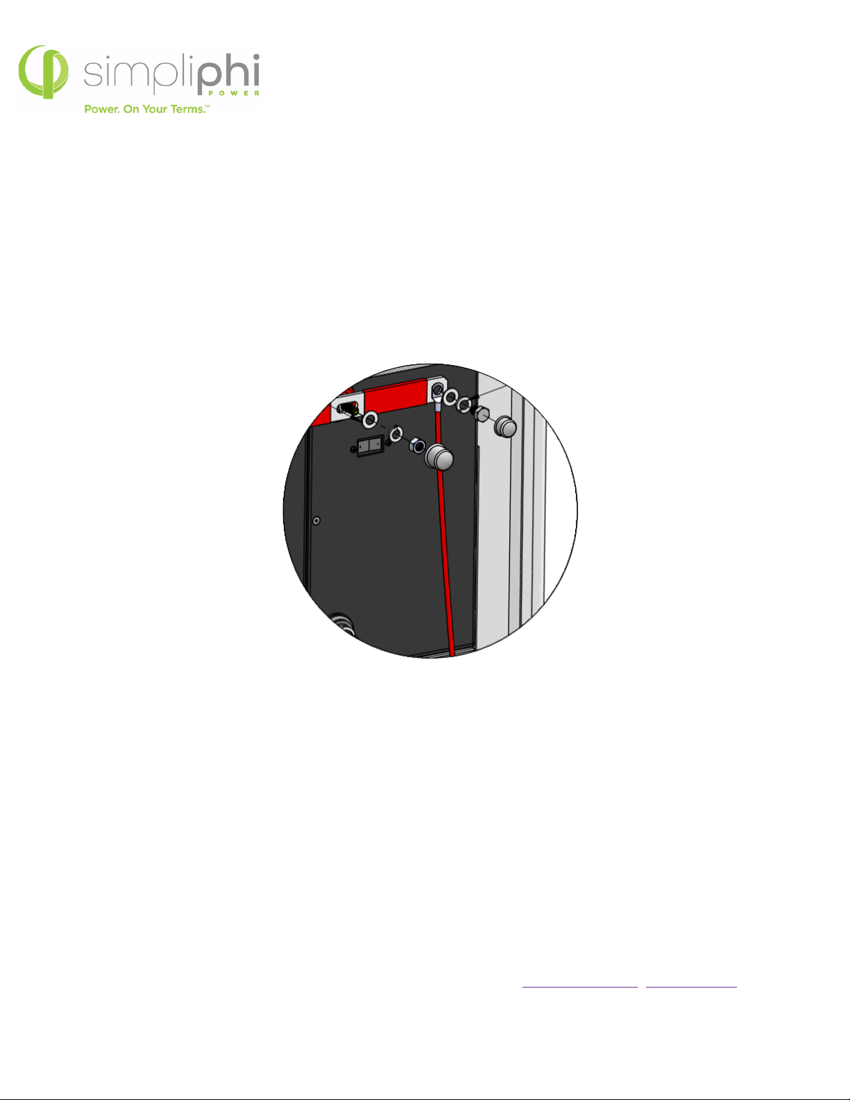
ii) Secure the cable lug(s) to the positive 5-point terminal block using a 17mmwrench socket to
tighten the ¼”-20 nut(s). The cables should include 3/8” lugs to fit onto the 3/8” posts on the
5-point terminal block.
iii) Size the battery bussing-to-terminal block wires according to the number of batteries
connected in parallel and in compliance with local codes. Refer to Table 3 for guidance.
Figure 4 – Cables Wired from Each Interconnecting Busbar to the 5-Point Terminal Busbar
3 Battery Busbars = SKU# BB-3
(interconnecting busbar-to-terminal busbar
wiring
not included)

REV020620
SimpliPhi Power, Inc. | 3100 Camino Del Sol | Oxnard, CA 93030, USA | (805) 640-6700 | [email protected]| SimpliPhiPower.com
| 14 |
12. Route battery-to-inverter cables (not included) through conduit (also not included) using the desired
knockouts on the side of the BOSS.6 Enclosure. DC Positive and DC Negative cables run from the
Enclosure’s 5-point terminal blocks to the inverter power panel of any equipment compatible with
SimpliPhi’s batteries (refer to the Integration Guides listed in the Product Documentation section of
SimpliPhi’s web page for a list of compatible equipment: https://simpliphipower.com/product-
documentation/).
13. Set the circuit breakers for all battery modules to the ON position. PHI batteries must be fully charged
before commissioning.
CAUTION: Turn the inverter’s main DC Disconnect on only AFTER ALL the built-in circuit
breakers in the PHI Battery bank are turned on. (Refer to the System Commissioning
SimpliPhi battery video.)
This completes the installation procedure for the BOSS.6 Enclosure.
Remember, all Balance of System equipment must be programmed to SimpliPhi’s specified
settings and PHI batteries must be fully charged before commissioning the system (i.e.
before connecting the batteries to any loads).
4.0 – Care & Maintenance
The BOSS.6 Enclosure is designed to deliver many years of reliable service in a wide variety of
environments. The BOSS.6 is resistant to most environmental elements, but should be isolated from
excessive water or moisture, extreme heat, solvents, flammable materials, and environmental hazards.
If the BOSS.6 becomes dirty or grimy, wipe it as you would any kitchen cabinet. Do not use a pressure
washer or hose to clean the BOSS.6.

REV020620
SimpliPhi Power, Inc. | 3100 Camino Del Sol | Oxnard, CA 93030, USA | (805) 640-6700 | [email protected]| SimpliPhiPower.com
| 15 |
5.0 – Technical Support
For technical support related to your BOSS.6 Enclosure, please contact us as at:
805.640.6700
techsupport@simpliphipower.com
Table of contents
Other SimpliPhi Power Storage manuals


