SINCOLD AS.003 Instructions for use

ENGLISH
BLAST CHILLER AND DEEP FREEZER
OPERATING INSTRUCTIONS AND MAINTENANCE
MODELS:
AS.003 (3.10) / AS.005C (5.12) / AS.005ST (5.12) / AS.005 (5.15) /
AS.005 (5.20) / AS.007 (7.20) / AS.007 (7.30) / AS.010 (10.30) / AS.014 (14.30)
INDEX
PAGE
1.
GENERAL INFORMATION 3
1.1. SPECIFICATIONS OF THE BLAST CHILLER-DEEP FREEZER 3
1.2. WARNINGS - SAFETY MEASURES 3
1.3. TRANSPORT AND TRANSFER 3
1.4. UNPACKING 3
2.
INSTALLATION 4
2.1. DATA PANEL (OR OPERATING SPECIFICATIONS) 4
2.2. AMBIENT CONDITIONS 4
2.3. POSITION 4
2.4. CONNECTION TO THE ELECTRIC NETWORK 4
2.5. CONNECTION TO THE REFRIGERATING UNIT (ARRANGED WITH REMOTE UNIT) 5
2.6. WATER CONNECTION (FOR WATER CONDENSED MODELS) 5
3.
OPTIMIZATION OF THE WORKING CYCLES 6
4.
FUNCTIONING 6
4.1. DESCRIPTION OF THE WORKING CYCLES 6
4.2. CONTROLLER 7
4.2.1. SWITCHING ON AND OFF OF THE BLAST CHILLER 7
4.2.2. FUNCTIONING 7
4.2.2.1. TEMPERATURE BLAST CHILLING SOFT WITH CORE PROBE (1) + CONSERVATION 7
4.2.2.2. TIME BLAST CHILLING SOFT (5) + CONSERVATION 7
4.2.2.3. TEMPERATURE BLAST CHILLING HARD WITH CORE PROBE (2) + CONSERVATION 8
4.2.2.4. TIME BLAST CHILLING HARD (6) + CONSERVATION 8
4.2.2.5. TEMPERATURE DEEP FREEZING HARD WITH CORE PROBE (3) + CONSERVATION 8
4.2.2.6. TIME DEEP FREEZING HARD (7) + CONSERVATION 8
4.2.2.7. TEMPERATURE DEEP FREEZING SOFT WITH CORE PROBE (4) + CONSERVATION 8
4.2.2.8. TIME DEEP FREEZING SOFT (8) + CONSERVATION 8
4.2.3. PRE-COOLING 9
4.2.4. PROBES DISPLAY 9
4.2.5. DEFROST 9
4.2.6. EXAMPLE OF SOFT BLAST CHILLING 9
4.3. RAW FISH SANITATION CYCLE 9
4.4. CONTROL AND SECURITY DEVICES (ALARMS AND CONTROLS) 10
5.
ORDINARY MAINTENANCE 10
5.1. WARNINGS 10
5.2. INTERIOR CLEANING 10
5.3. CLEANING OF THE CONDENSER 10
6.
EXTRAORDINARY MAINTENANCE 11
7.
BREAKDOWNS 11
8.
DISMANTLING OF THE MACHINE 11
9.
DIMENSIONS (mm) AND DATA PANEL 12
10.
WIRING DIAGRAMS 13

ENGLISH

ENGLISH
3
1.
GENERAL INFORMATION
1.1. SPECIFICATIONS OF THE BLAST CHILLER-DEEP FREEZER
This manual contains the instructions for the correct installation, use and maintenance of your blast chiller-deep freezer and should always
follow the machine and be passed on to any future owner.
Please carefully read following instructions before starting any operation, so as to avoid any hazards to people or things and to obtain the best
performance from this appliance.
This manual should be kept in a safe place, accessible to all authorized people: the installer, the user, the person in charge for maintenance and
dismantling.
The use of the blast chiller is reserved to professionals and qualified personnel only. Keep children away and make sure they do not play with it
or touch the control board. This unit is designed to blast chill food only. Any other use is considered improper and dangerous.
1.2. WARNINGS - SAFETY MEASURES
The manufacturer shall not be liable for any damages to people or things which are caused by improper installation and use.
Following operations are therefore strictly forbidden:
The installation and maintenance carried out by non-specialized or non-authorized personnel.
The installation of the unit carried out incorrectly, without following the manufacturer’s instructions.
Use by untrained personnel.
Non authorized modifications or technical interventions.
The removal of protection and security devices.
The connection to non-approved appliances.
The use of non-original accessories and spare parts.
The alteration by unauthorized personnel.
The carrying out of any modifications in the appliance.
Touching the appliance with wet hands or feet.
Placing any kitchen tools or other instruments between the fan blades and suction grills.
Before starting any cleaning or maintenance operations, always switch the blast chiller off and take the plug off the socket, taking care not to
pull the cable.
Make sure that the cable is not squashed or pulled during transport or installation.
The plug must always be disconnected in case the unit is not used for a long period.
The technician in charge for installation is expected to respect all prescriptions concerning: hygienic and sanitary regulations, fire and accident
regulations and all norms concerning electrical supply.
Do not introduce any explosive gases and liquids in the machine, e.g. gas for lighters, petrol, ether, acetone or others.
The blast chiller is not a refrigerated cabinet.
As soon as the working cycles are over, the unit turns automatically into a temporary – and transitional - conservation phase. At the end of the
cycle, the product is to be stored in an appropriate refrigerator.
As deep-freezing of foodstuff is regulated by law, a qualifying license issued by the Local Health Authority is needed.
Regulation (EC) no. 842/2006.
The blast chillers-deep freezers containing 3 kg or more of refrigerant gas (see table at p. 12) must be checked for leakage at least once a year.
The operators of the blast chillers
-deep freezers must maintain records of the quantity of gas installed and the quantity possibl
y added or
reclaimed during servicing, reparation and final disposal.
1.3. TRANSPORT AND TRANSFER
The transfer of the blast chiller should be carried out by using an electric or manual fork-lifter and be lifted from the bottom. Remove the drip
tray placed under the unit (if previously placed under it).
Make sure that the lifter capacity is higher than the weight of the blast chiller. This information is reported on the packing label and on the
data panel on the side of the unit.
Lift the unit and make sure that it's kept in stable balance.
If the unit is shipped on a truck, fasten it to the sides of the truck body through a fixing cable.
It is recommended to keep the blast chiller very close to the ground during transfers – the maximum allowed lifting height is 10 cm.
If the unit is to be lifted higher, it should be placed on a wooden platform and lifted jointly.
The weight of the unit is not to be underestimated: its size and volume might be deceiving.
Do not turn the unit upside down or lean it on its sides, so as to prevent severe damage to the structure.
If not placed in a wooden cage or on a platform, the unit can be lifted through cables.
The use of gloves is always recommended when handling the unit and its packaging.
1.4. UNPACKING
Remove the cartons and the polystyrene, lift the unit (see par. 1.3) by a suitable means, remove the wooden platform and place the blast chiller
on the floor near the installation site. Check the integrity of the unit and ensure that it has not been damaged during shipment. If any damage
should have occurred, it has to be immediately reported to the supplier.
Keep the packaging away from children: the plastic wrapping may cause suffocation.
Use protective gloves while executing these operations.
Dispose packaging appropriately by taking it to the local recycling centre.

ENGLISH
4
2.
INSTALLATION
2.1. DATA PANEL (OR OPERATING SPECIFICATIONS)
Make sure that the operating parameters indicated on the data panel (V tension, Hz frequency, kW electrical power) comply with the ones of
the installation site.
The data panel, with information and characteristics of the unit, is applied on the left side of the unit. Models AS.003 (3.10), AS.005C (5.12)
and AS.005ST (5.12) have it on the back side.
2.2. AMBIENT CONDITIONS
The operating temperature range for air cooled units lies between +10°C and +32°C. If the temperature exceeds these limits the declared
output and performances can be compromised and critical conditions may cause the intervention of the security switch (or security devices).
It is therefore recommended not to place the unit next to any source of heat or expose it to direct sunlight. The least clearances indicated in the
next 2 paragraphs should be respected.
2.3. POSITION
Place the blast chiller in the selected position and provide to keep at least 10 cm from the back wall (see p. 12) and enough space in the front
side for air intake. The blast chillers equipped with remote unit should be installed following the indications mentioned in the
previous section (2.2), thus avoiding to place them next to any source of heat, even other compressor units or heat pumps.
The unit must lay on a flat, steady and firm ground, so as to provide stability to all four corners and should not lean against other appliances.
The legs can be adjusted manually or with a proper spanner for models AS.003 (3.10).
The blast chiller lowers.
The blast chiller lifts up.
Slide the drip tray (optional in mod. AS.003 (3.10)) along the runners placed in the front bottom of the unit.
If the blast chiller is not correctly leveled, its functioning and condensation flow may be compromised.
In the roll-in units the condensation drain should be kept free at least 20 mm from the nearby drain.
Remove the protective film and clean the machine inside and outside, using protective gloves. Wash the unit inside using a light detergent,
avoiding the use of steel wool, abrasive sponges, solvents or any other products which might corrode or scratch the surfaces.
2.4. CONNECTION TO THE ELECTRIC NETWORK
The electric connection is to be carried out through the supply cable coming out at the back of the unit. For roll-in models the instructions
mentioned in the attached technical specifications must be respected. The cable is never to be pulled or damaged (danger of electrical accident).
A damaged electrical cable must be immediately replaced by a qualified and authorized electrician.
The blast chiller is to be connected to an inter-blocked plug with an effective ground wiring. The machine is non-operational only when the plug
is not plugged into the socket.
Install a safety switch of 30 mA on the electric supply board to grant protection for people. Make sure that the ground system is properly
connected with the clamp (PE) through a cable with a minimum section of 16 mm
2
.
Provide the coordination against contact tensions, equipotential connection, through the clamp identified by the symbol .
Make sure that the voltage (V) and frequency (Hz) correspond to the ones indicated on the data panel (see page 12).
Before connecting the cable to the power point, the machine needs to be positioned upright for at least thirty minutes; four hours waiting time
are needed if the unit was transported laid on
its side. The liquid of the refrigerating system needs some time to stabilize, otherwise the
compressor may be damaged.

ENGLISH
5
2.5. CONNECTION TO THE REFRIGERATING UNIT (ARRANGED WITH REMOTE UNIT)
The installation of blast chillers with remote compressor unit must always be carried out in compliance with the regulations concerning the
prevention of accidents, regulation and obligations of electric norms, noise and environmental impact. The possible installation of a compressor
unit in a closed room (e.g. machines room), must be carried out in compliance with the regulations in force in the country of installation. It is
very important to consider that in particular circumstances, for example in case of improper functioning, an escape of refrigerating gas can
occur th
rough the security valve or fuse cap installed in the refrigerating unit: it is therefore necessary to provide immediate air
circulation and
start first aid measures as indicated on the refrigerant security label.
The performances are guaranteed for the installation of the remote unit at a maximum distance of 10 meters.
The dimensions of the pipes must comply with the ones indicated in the table. The insulation of the air suction pipes must be at least 13 mm
thick and be made of a material suitable for refrigeration circuits.
Different installation levels between the blast chiller and its compressor unit need particular arrangements to ensure the faultless operation of
the unit:
compressor unit installed higher than the blast chiller: install a syphon at each rise and any further rise, all 2 meters gradient
along the suction pipe;
unit installed lower than the blast chiller: no syphons are needed, the pipe inclination towards the compressor unit should be
respected, at least 3mm/mt.
Gas proof soldering must be executed and the pipes must be emptied through both service taps. Check for eventual leaks, turn on the taps in
the compressor unit and add gas R404A, if necessary, checking the liquid sign. Add oil, type Artic 32 synthetic, if necessary
,
checking the oil
warning sign (where present).
A
Suction
B
Inlet
AS.005 (5.15) Ø 12mm Ø 6mm
AS.005 (5.20) Ø 12mm Ø 8mm
AS.007 (7.20) Ø 12mm Ø 8mm
AS.007 (7.30) Ø 12mm Ø 8mm
AS.010 (10.30) Ø 16mm Ø 12mm
AS.014 (14.30) Ø 16mm Ø 12mm
A = Minimum distance from wall 1mt
B = Remote unit
C = To be executed about every 2mt
D = Inlet and suction pipes
E = 3mm/mt gradient towards remote unit
F = Blast chiller – deep freezer
In case it were necessary to add gas
during installation, the quantity of
gas added must be marked as “PLUS”
and “TOTAL” on the label featured in
picture.
2.6. WATER CONNECTION (FOR WATER CONDENSED MODELS)
Connect the water flow-in pipe as well as the drainpipe, as indicated on the plate on the back of the unit. Use network water with minimum
pressure of 100 kPa and a maximum of 500 kPa. The water temperature shall not exceed +18°C.
Do not use sea water. The specific models are available upon request.
Install a tap on the entrance pipe. The water drain must be in free air at least 20 mm from the nearby drain.
With still unit check for any water leakage from the drainpipe. If this were the case, slightly turn the pressure valve off ( ¼ of a turn).
Attention! The missing water flow will cause the block of the unit and the activation of the security switch HP.
Minimum distance between water drain and floor or other surface.

ENGLISH
6
3.
OPTIMIZATION OF THE WORKING CYCLES
PRE-COOLING: Pre-cool the unit before starting a chilling or deep-freezing cycle, so as to reduce the working times.
CORE PROBE: The core probe must be properly positioned at the core of the thickest part of the product. Its point shall neither come out
nor touch the tray. The probe must be cleaned before starting any cycle, in order to prevent any contamination.
LIDS AND CONTAINERS: Do not cover the trays and/or containers with lids or insulating films. The more the product surface gets in
contact with the airflow, the less it will take to chill and deep-freeze it. Do not use bowls or trays deeper than 40 mm.
DISTRIBUTION OF THE PRODUCT: Do not lay portions of product upon each other. The product thickness must not exceed 50 mm:
this would make the chilling / freezing times longer. Do not overload the unit beyond the quantity recommended by the manufacturer.
SPACE BETWEEN THE TRAYS: Allow enough space between the trays in order to grant a proper airflow. Place them evenly inside the
unit.
CONSERVATION: At the end of the cycle the chilled and/or frozen product must be covered and protected (film, airtight, hermetic
sealing).The chilled product needs to be conserved in a storage refrigerator at a uniform temperature of +2°C. The frozen pro
duct is to be
conserved in a storage refrigerator at a uniform temperature of -20°C.
Mark the containers of the chilled/frozen product with an appropriate label, clearly indicating content and expiry date.
The blast chiller is not a refrigerated cabinet.
As soon as the working cycles are over, the unit turns automatically into a temporary – and transitional - conservation phase.
At the end of the cycle, the product is to be stored in an appropriate refrigerator.
4.
FUNCTIONING
4.1. DESCRIPTION OF THE WORKING CYCLES
This blast chiller-deep freezer is a high performance appliance and can be used at best exploiting all its functions.
The standard working cycles are as follows:
TEMPERATURE BLAST CHILLING SOFT WITH CORE PROBE (1) + CONSERVATION
This cycle reduces the food temperature to +3°C at the core of the product, with chamber temperature around 0°C. Suitable for delicate or
thin products.
TEMPERATURE BLAST CHILLING HARD WITH CORE PROBE (2) + CONSERVATION
This cycle reduces the food temperature down to +3°C at the core of the product, with chamber temperature from –18°C to 0°C. Suitable
for fat products and large pieces, it allows a quick reduction of working times and is also suitable for full load cycles.
TEMPERATURE DEEP FREEZING HARD WITH CORE PROBE (3) + CONSERVATION
This cycle reduces the food temperature to –18°C at the core of the product. The duration of the working cycle depends anyway from
several factors, such as the product type, its thickness, the container used.
TEMPERATURE DEEP FREEZING SOFT WITH CORE PROBE (4) + CONSERVATION
This cycle reduces the food temperature to –18°C at the core of the product. This is indicated for delicate or thin products. The duration of
the working cycle depends anyway from several factors, such as the product type, its thickness, the container used.
TIME BLAST CHILLING SOFT (5) + CONSERVATION
This cycle has the same characteristics of cycle no. 1, with the only difference that time setting is required instead of using the core probe.
TIME BLAST CHILLING HARD (6) + CONSERVATION
This cycle has the same characteristics of cycle no. 2, with the only difference that time setting is required instead of using the core probe.
TIME DEEP FREEZING HARD (7) + CONSERVATION
This cycle has the same characteristics of cycle no. 3, with the only difference that time setting is required instead of using the core probe.
TIME DEEP FREEZING SOFT (8) + CONSERVATION
This cycle has the same characteristics of cycle no. 4, with the only difference that time setting is required instead of using the core probe.
PRE-COOLING (9)
This function allows the pre-cooling of the chamber, so as to create the best conditions for the introduction of the product to be chilled and
frozen and reduce the chilling or freezing times accordingly.

ENGLISH
7
4.2. CONTROLLER
LED
Celsius degree
Fahrenheit degree
Minutes
On / Stand-by
Conservation
Time blast chilling / freezing
Temperature blast chilling / freezing
Defrost
Blast chilling hard / freezing
Freezing
Blast chilling
H.A.C.C.P.
Pre-cooling
BUTTON
On / Off
Start / Stop
Defrost
Increase
Menu
Decrease
Pre-cooling
Blast chilling
Freezing
Hard
4.2.1. SWITCHING ON AND OFF OF THE BLAST CHILLER
Press the button for one second, the led will light up or go off.
4.2.2. FUNCTIONING
After having switched the unit on with the button (see point 4.2.1) start the selected cycle as follows:
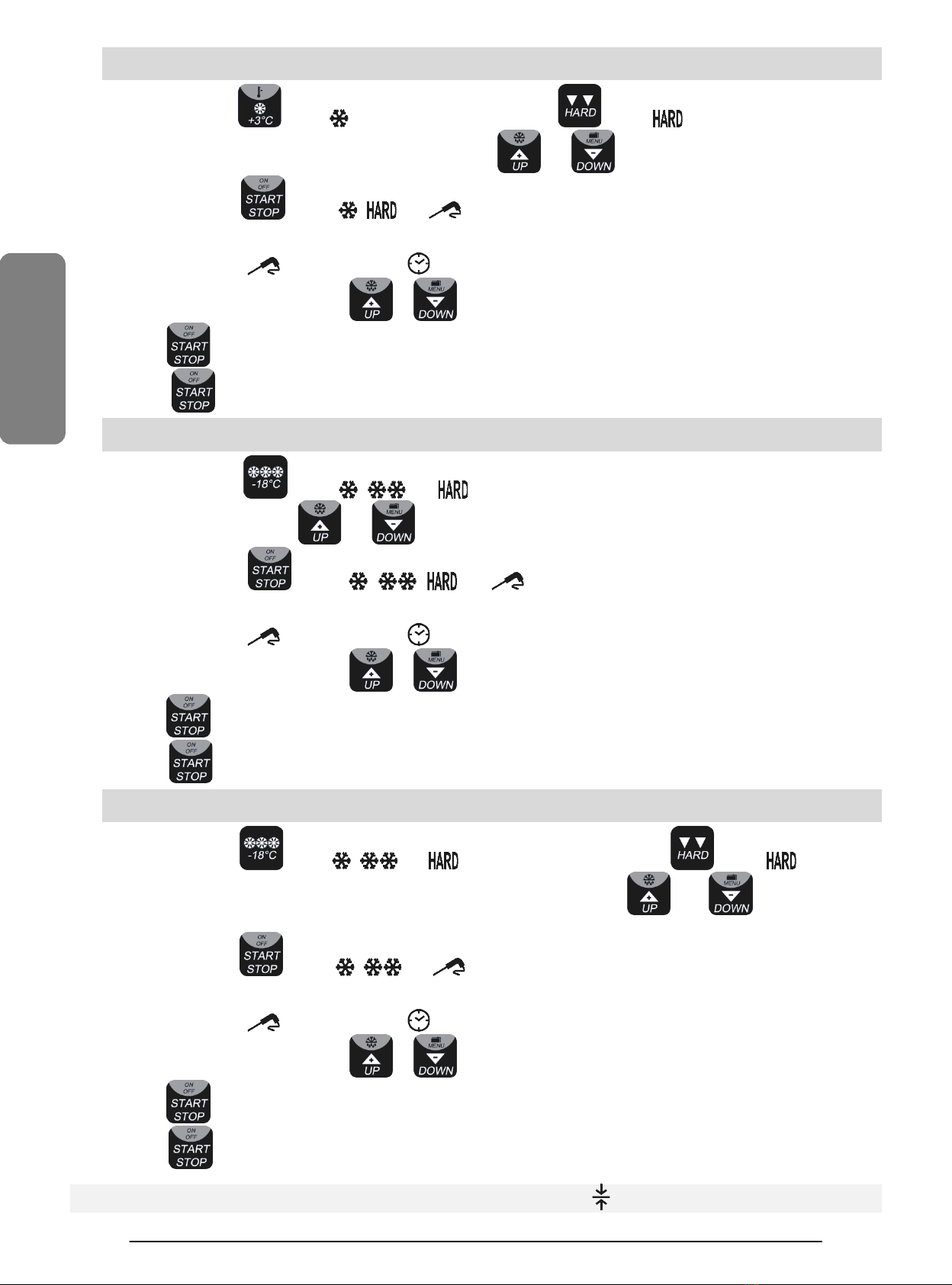
4.2.2.1. TEMPERATURE BLAST CHILLING SOFT WITH CORE PROBE (1) + CONSERVATION
4.2.2.2. TIME BLAST CHILLING SOFT (5) + CONSERVATION
Press and release the button
the led
will start flashing, the display will show the temperature of end cycle, which can be modified
with the buttons and (the value +3.0 is recommended).
Press and release the button
, the led and
will be steadily lighted and the working cycle including the conservation phase
will start. The check for the correct introduction of the core probe will be activated. If this test is successfully executed
, t
he cycle will go on in
temperature mode
(1); if the test is not successfully executed, the cycle will go on as time cycle in mode (5), the led
will go off and the
led will switch on.
At this point, within 5 minutes, press the button or to change the duration of the cycle in execution.
Keep the button pressed to interrupt the cycle.
Press the button to stop the conservation phase.
ENGLISH
8
4.2.2.3. TEMPERATURE BLAST CHILLING HARD WITH CORE PROBE (2) + CONSERVATION
4.2.2.4. TIME BLAST CHILLING HARD (6) + CONSERVATION
Press and release the button
the led will start flashing, press the button , the led will start flashing
, the display will
show the temperature of end cycle, which can be modified with the buttons and (the value +3.0 is recommended).
Press and release the button
, the led , and
will be steadily lighted and the working cycle including the conservation
phase will start. The check for the correct introduction of the core probe will be activated.
If this test is succes
sfully executed, the cycle will go on in temperature mode (2)
; if the test is not successfully executed, the cycle will go on as
time cycle in mode (6), the led will go off and the led will switch on.
At this point, within 5 minutes, press the button or to change the duration of the cycle in execution.
Keep the button pressed to interrupt the cycle.
Press the button to stop the conservation phase.
4.2.2.5. TEMPERATURE DEEP FREEZING HARD WITH CORE PROBE (3) + CONSERVATION
4.2.2.6. TIME DEEP FREEZING HARD (7) + CONSERVATION
Press and release the button
the led , and will start flashing,
the display will show the temperature of end cycle,
which can be modified with the buttons and (the value −18.0 is recommended).
Press and release the button
, the led , , and
will be steadily lighted and the working cycle including the
conservation phase will start. The check for the correct introduction of th
e core probe will be activated.
If this test is successfully executed, the cycle will go on in temperature mode
(3)
; if the test is not successfully executed, the cycle will go on as
time cycle in mode (7), the led will go off and the led will switch on.
At this point, within 5 minutes, press the button or to change the duration of the cycle in execution.
Keep the button pressed to interrupt the cycle.
Press the button to stop the conservation phase.
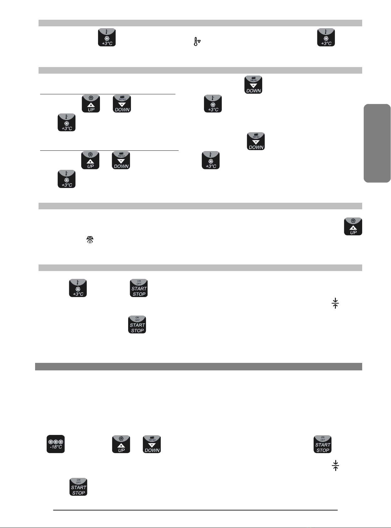
4.2.2.7. TEMPERATURE DEEP FREEZING SOFT WITH CORE PROBE (4) + CONSERVATION
4.2.2.8. TIME DEEP FREEZING SOFT (8) + CONSERVATION
Press and release the button
the led , and will start flashing, press the button , the led will go off,
the
display will show the temperature of end cycle, which can be modified with the buttons
and (the value −18.0
is
recommended).
Press and release the button
, the led , and
will be steadily lighted and the working cycle including the conservation
phase will start. The check for the correct introduction of th
e core probe will be activated.
If this test is successfully executed, the cycle will go on in temperature mode
(4)
; if the test is not successfully executed, the cycle will go on as
time cycle in mode (8), the led will go off and the led will switch on.
At this point, within 5 minutes, press the button or to change the duration of the cycle in execution.
Keep the button pressed to interrupt the cycle.
Press the button to stop the conservation phase.
At the end of any cycle the unit turns automatically into conservation and the led will light up.
ENGLISH
9
4.2.3. PRE-COOLING
Press one second the button
to start the pre-cooling, the led will start flashing. Press one second the button
to stop the
pre-cooling, or just start a working cycle.
4.2.4. PROBES DISPLAY
Display of the chamber temperature during a cycle: press one second the button , the display will show rCH. Select
Pb1
with the buttons and , press and release the button
, the display will show the chamber temperature. Press the
button to quit.
Display of the core probe temperature during a cycle: press one second the button , the display will show rCH. Select
Pb2
with the buttons and , press and release the button
, the display will show the core probe temperature. Press the
button to quit.
4.2.5. DEFROST
Defrost starts automatically during the conservation phase.
It’s possible to start defrost manually. Make sure that the unit is switched on or a conservation phase is in progress, press
the button
for four seconds, the led will light up. If the chamber temperature is above 2°C the defrost will not be executed.
4.2.6. EXAMPLE OF SOFT BLAST CHILLING
With unit in standby, slide the trays with the product to be blast chilled into the rack. Stick the core probe into the product. Close the door,
press the button , press the button and the unit will start the working cycle.
Once the temperature of
+3°C at the core of the product is reached, the unit will turn automatically into conservation. The led
will light
up.
To take the product out, press the button
to stop the unit, remove the core probe and lay it back into the probe holder, take the trays
out and store the product in the provided refrigerated cabinets.
4.3. RAW FISH SANITATION CYCLE
The raw fish sanitation cycle consists in a special deep freezing cycle to -20°C at the core of the product, followed by a 24 hours maintenance
stage. This kind of sanitation is required by the
Italian sanitary authority for all seafood served raw or semi-raw
(not previously subjected to
any s
anitation cycle). This treatment protects
the consumer from alimentary toxic infection caused by sea bacteria (such as ANISAKIS
bacteria). ATTENTION: this specific sanitation is required in Italy.
Other Countries may regulate the matter differently and requirements may be different to what executed by the raw fish sanitation cycle.
The constructor is not liable for any violation of food sanitary laws customers can incur in using this appliance.
Contact the sanitary authority to be informed about raw fish prophylaxis in your Country.
To execute a cycle follow instruction:
With unit in standby, slide the trays with the product to be frozen into the rack. Stick the core probe into the product. Close the door, press the
button
, press the buttons and to set the final freezing temperature at −20.0,press the button
and the unit
will start the working cycle.
Once the temperature of
−20°C at the core of the product is reached, the unit will turn automatically into conservation. The led
will light
up. The conservation must last at least 24 hours.
Press the button to stop the conservation phase.

ENGLISH
10
4.4. CONTROL AND SECURITY DEVICES (ALARMS AND CONTROLS)
The control devices available in this unit, if activated, will be displayed will following symbols:
id
open door: the cycle stops and will be restarted from the point of interruption once the door is closed again.
HP
alarm high pressure.
AL
alarm minimum temperature.
AH
alarm maximum temperature (alarm H.A.C.C.P.)
.
Pr1
error chamber probe.
The activation of one of these alarms prevents the cycle start. If a cycle is in progress it will be blocked.
Pr2
error core probe: in this case
it’s not possible to start a temperature cycle. However, all time cycles can be executed.
Each warning is joined to an acoustic alarm. Press any button to stop it.
5.
ORDINARY MAINTENANCE
5.1. WARNINGS
Carefully read all security and warning instructions in the introduction page.
The manufacturer is not liable for any damages caused by improper operations or by any improper use of the appliance, as from the
specifications of this instruction manual.
It is necessary to remind users about some basic operations to be carried out before starting cleaning:
Disconnect the machine from the electrical feeding network unplugging the main switch and the feeding plug.
Use protective gloves to protect the hands.
Do not introduce any tools, screwdrivers or other instruments between the moving parts or the protection elements.
Do not pierce pipes, or open the gas valves.
Do not pull the feeding cable.
Do not remove protective and security devices while carrying out ordinary maintenance operations.
5.2. INTERIOR CLEANING
The machine must be cleaned either inside and outside before starting any working cycle and at the end of any cycle, thus
preventing the arising of germs, bacteria, virus and unpleasant smells – together with anything else that may harm food.
The machine must be cleaned using degreasing and disinfectant products commonly used in the kitchen. Avoid steel wool, abrasive sponges,
solvents and any products, which might corrode or scratch the surfaces.
In short, the blast chiller must be clean when used and must be left clean at the end of every working session.
The racks are easily removable for cleaning. Reposition them once they have been washed.
It is important to carefully wash the inside of the unit and the door.
Do not scrape with sharp tools, especially the cool generator.
Remove the drain cap on the bottom of the chamber to let the water flow out and put it back before starting a new working cycle. The waste
water will be drained into the drip tray (optional in mod.
AS.003 (3.10)), which will be emptied and cleaned every day by pulling it out
from the
front bottom of the unit.
Keep the door ajar, so as to allow air circulation inside the chamber and prevent bad smells and mould from developing.
Prevent any salt pouring on the surfaces of the blast chiller: if this should occur, clean the surface properly and immediately.
5.3. CLEANING OF THE CONDENSER
The condenser needs to be cleaned at least all 2 months. In the air cooled models, the condenser is placed on the front side of the unit, whereas
the models equipped with remote unit have the condenser in the group itself. This important operation ensures the proper functioning of the
unit and avoids the intervention of the security switch (HP).
Put protective gloves on to carry out these operations: the condenser tongues are very sharp. Also use protective glasses and a protection mask
for the respiratory tract.
Carefully follow the instructions listed here below:
Disconnect the plug from the power point before starting;
In case of models AS.003 (3.10), AS.005C (5.12) and AS.005ST (5.12) blow an air jet into the condenser placed in the front of the unit;
On all other models strongly pull the front panel;
Turn the board carefully over in order to prevent damages to the control board;
Clean the condenser by removing all dust and down deposits, using a brush or aspirator along the wings, making sure not to bend them; in
case of greasy deposits, remove them by using a little brush dipped in alcohol;
Once finished, close the front panel;
Roll-in units have the condenser is at sight.

ENGLISH
11
6.
EXTRAORDINARY MAINTENANCE
All operations of extraordinary maintenance must be carried out by specialized personnel only, authorized to operate on electric and
refrigerating parts. The following section gives indications and suggestions on how to manage and solve possible breakdowns or functioning
problems.
Contact our dealers for service, always reporting model and serial number indicated on the specification plate attached on the left side of the
unit.
Original spare parts are available at our Technical Service Centres only.
7.
BREAKDOWNS
The following table is a valid and very useful self-support chart for possible problem-solving solutions to any kind of malfunctioning.
MALFUNCTIONING CAUSE SOLUTION
The controller doesn’t
switch on
Tension missing.
Check the line tension and make sure that the plug is
plugged-into the feeding board.
Breakdown of the feeding line protection fuses. Service by a technician.
The unit is not cooling Malfunctioning of the compressor group. Service by a technician.
Long chilling / freezing
times
The portions of product are too big or the trays
position is not correct.
Remove some product so as not to exceed the
recommended weight (see par. 3).
Overloaded unit. See par. 3.
Excessive creation of frost
on the evaporator
Continuous execution of cycles with no pauses.
Execute a manual defrost between two cycles keeping
the door open (see par. 4.2.5.).
Water drain cap missing. Place back the cap onto the drain.
The compressor is not
working
Activation of protection. Service by a technician.
The fan is not working Broken fan. Service by a technician.
The compressor works but
the unit is not chilling
Freon missing. Service by a technician.
Broken line solenoid valve. Service by a technician.
id
Open door. Close the door.
Broken microswitch. Service by a technician.
HP
Dirty condenser. Clean the condenser (see par. 5.3).
Space missing for a correct airflow on the front and/or
back of the unit.
Move to unit to allow a better airflow (see par. 2.3).
Water missing (in models with water condensation).
Make sure that the water tap is open and restore the
water flow.
Inappropriate ambient temperature (see par. 2.2).
Place the unit in a cooler place or with better air
circulation.
Alarm continues even after the solution suggested. Service by a technician.
AL Check the chamber temperature. Service by a technician.
AH Check the chamber temperature. Service by a technician.
Pr1 Broken chamber probe. Service by a technician for replacement.
Pr2 Broken core probe. Service by a technician for replacement.
8.
DISMANTLING OF THE MACHINE
The dismantling of the machine should be carried out respecting following warnings: unplug the unit from the power point and cut the feeding
cable as much near as possible to the unit. Take the doors away and keep children away from the unit, take care not
to damage the
refrigerating system inside or in the back. The blast chiller does not contain any harmful substance for the ozone layer. The
refrigerant gas is
indicated on the plate outside the unit.
This product is projected and manufactured with high quality materials and components, which can be recycled and reused.
The symbol of a crossed bin with wheels applied on the product means that the product complies with the European Directive 2002/95/EC.
You are required to get all information on this subject at your local recycling centre.

ENGLISH
12
9.
DIMENSIONS (mm) AND DATA PANEL
AS.003 (3.10) AS.005C (5.12)
655 x 715 x 510/530 (L x P x Hmin/Hmax)
655 x 715 x 685/715 (L x P x Hmin/Hmax)
AS.005ST (5.12) AS.005 (5.15) / AS.005 (5.20)
655 x 710 x 755/785 (L x P x Hmin/Hmax)
798 x 700 x 835/865 (L x P x Hmin/Hmax)
AS.007 (7.20) / AS.007 (7.30) AS.010 (10.30) / AS.014 (14.30)
798 x 815 x 995/1025 (L x P x Hmin/Hmax)
798 x 808 x 1810/1850 (L x P x Hmin/Hmax)
V
Ph
Hz
A
kW
kg
dB
R404A (Kg)
AS.003 (3.10)
230
1
50
4,3
0,8
60
<70
0,260
AS.005C (5.12) / AS.005ST (5.12)
230
1
50
5,0
0,9
80
<70
0,500
AS.005 (5.15)
230
1
50
5,5
1,0
100
<70
0,550
AS.005 (5.20)
230
1
50
7,0
1,3
100
<70
0,700
AS.005SG
230
1
50
2,0
0,3
85
<70
0,000
AS.007 (7.20)
230
1
50
7,0
1,3
130
<70
0,800
AS.007 (7.30)
230
1
50
8,5
1,5
130
<70
0,900
AS.007SG
230
1
50
2,0
0,3
110
<70
0,000
AS.010 (10.30)
230
1
50
9,0
1,6
190
<70
1,000
AS.010SG
230
1
50
2,5
0,4
190
<70
0,000
AS.014 (14.30)
230
1
50
9,0
1,6
190
<70
1,000
AS.014SG
230
1
50
2,5
0,4
190
<70
0,000
The manufacturer reserves the right to carry out modifications of the product without notice.
For different voltages and/or frequencies, quotations upon request.
ENGLISH
13
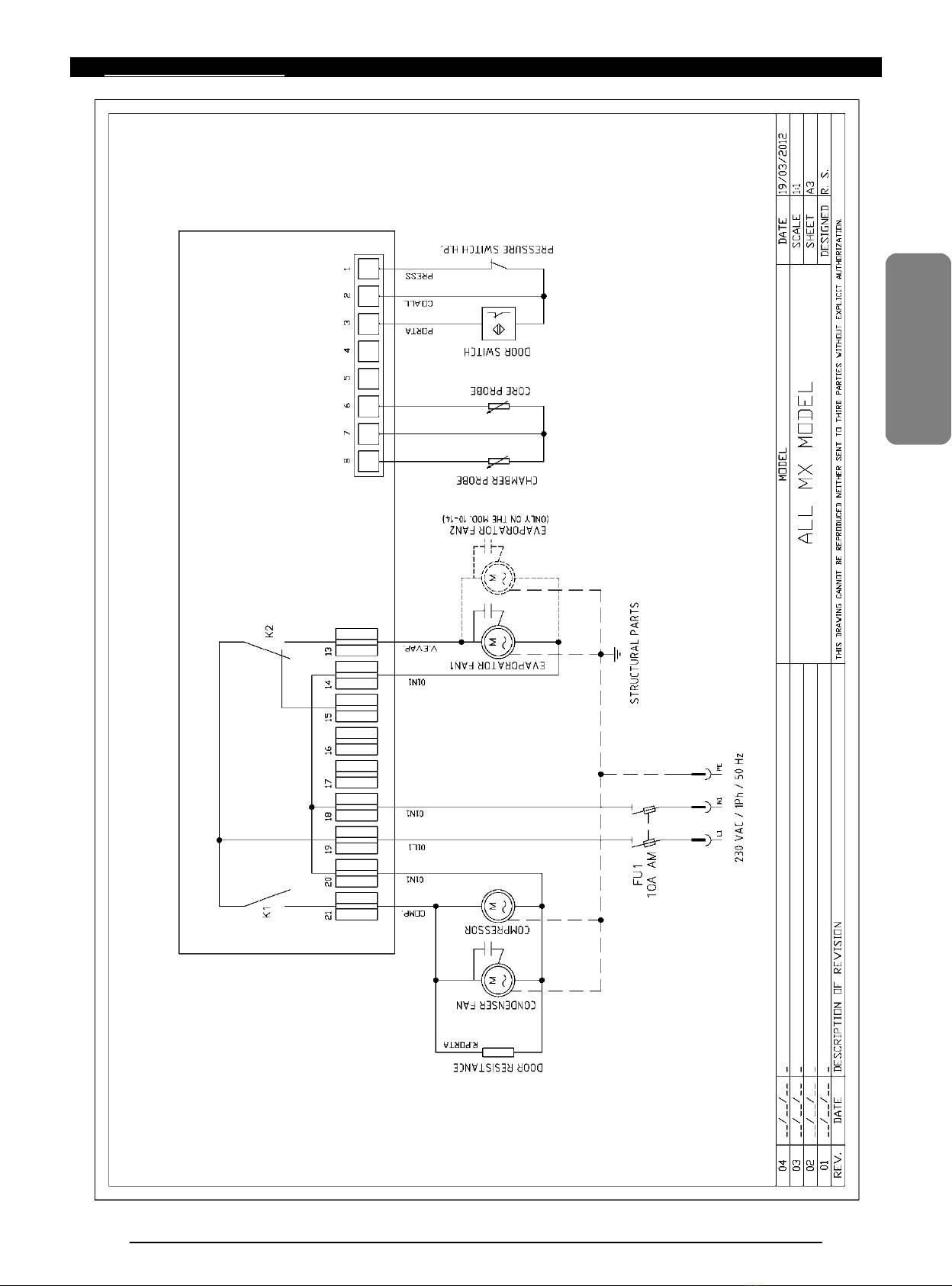
10.
WIRING DIAGRAMS

ENGLISH
14
NOTE:

ENGLISH

ENGLISH
ENG REV.02 02/2013
WARRANTY
Warranty of proper functioning.
A.T.O. s.r.l.. warrants for the proper functioning of the appliance, object of this sale, for a period of twelve months starting from purchase date to the original purchaser, not to successive purchasers.
The warranty hereto provides for the replacement of faulty parts returned ex-works, workmanship excluded. The replacement of the parts within the warranty period does not prolong the same warranty. The purchaser has no
compensation rights for damages due to the misuse of the machine.
The warranty is not applicable in the following cases:
•If the purchaser does not comply with the terms of payment;
•If damages are due to unskilled, unconventional use, overloading, poor care, tampering or modifications which were not authorized by the manufacturer, lack of or unstable power supply;
•If damages are due to an accidental case or force majeure;
•If the defects are not made known to A.T.O. s.r.l. in writing within eight days from their discovery, causing the loss of its effectiveness;
•If the notification does not include the detailed description of the claimed defect as well as its possible causes;
This warranty is not applicable to ordinary wear and tear of the machine.
A.T.O. s.r.l.. does not accept responsibility for the quality of the products obtained from the machine since this depends on different factors such as: the skilfulness and technique of the operator, quality and quantities of the
ingredients or materials used.
In the event that the notification is accepted, A.T.O. s.r.l. will replace those parts of the unit that are found damaged or faulty, on condition that the malfunction is due to production defects.
In the event that the notification is not accepted, A.T.O. s.r.l. reserves the right to hold this warranty valid, thus making known this intention - on pain of ineffectiveness, in writing (fax is admitted) or by phone, within five days
from receipt of the notification.
For the applicability of this warranty, the existence of a production defect is left to the exclusive technical assessment of A.T.O. S.r.l. , which will avail itself of its own or trusted personnel.
The warranty of proper function does not cover defects due to improper use of the product by the purchaser.
The warranty of proper functioning does not include (and therefore the corresponding expenses are paid by the purchaser):
•cleaning actions;
•any intervention work carried out to repair the unit when the unit could be repaired by the purchaser himself according to the instruction manual;
•any ordinary maintenance intervention needed for the normal use of the unit;
•any intervention carried out to remove damages due to power circuit failure or to causes related to the professional, commercial and industrial activity performed by the purchaser;
•any action performed to repair functioning defects due to bad maintenance of the unit by the purchaser or third parties appointed by the purchaser, or in the case that the maintenance was not performed according to the
provisions given by A.T.O. s.r.l.;
•any action performed to remove functioning defects due to abuses of the unit by the purchaser or third parties;
•any interventions aimed at repairing the faults caused by damages to the unit due to transport of the appliance from the headquarters of A.T.O. s.r.l.. to its destination.
The warranty hereto does not cover damages incurred by the purchaser due to non-use of the unit.
A.T.O. S.R.L.
Via dell’Artigianato, 24 - 31030 Castello di Godego - Treviso - Italy
Tel. (+39) (0)423-768270 / Fax (+39) (0)423-469539
www.sincold.it - info@sincold.com
This manual suits for next models
6
Table of contents


