SineWave Amplifiers CYN-DRIVE User manual

20 Watt, 50 Watt, 100 Watt Options
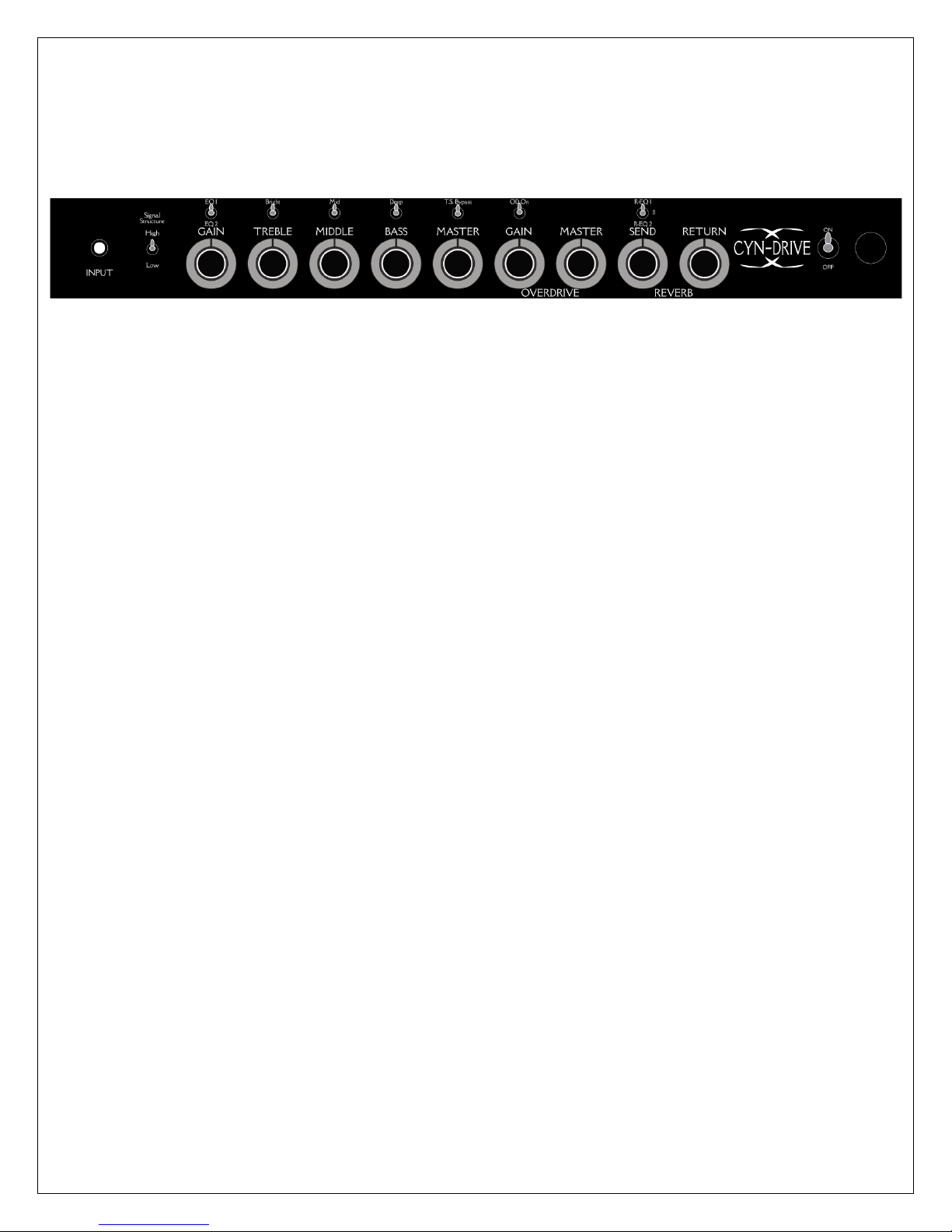
Front Panel Functions
- Input - Instrument input.
- - The Signal Strength circuit is designed to optimize the front end ofSignal Structure Switch
the amp and how it integrates into the back end of the preamp. This circuit offers two options:
oThe high is more akin to an old vintage blackface in the way the bass and gain
overpower the rest of the amp. This will instantly feel a bit more “old school” and will
also offer more gain and volume. Overall headroom on the preamp side will be lower in
this mode.
The Low is more modern and will decrease the amount of “hash” or harmonic distortion o
that most vintage amplifiers have. It will also help smooth out the signal if overdriven
from pedals. There will be more note separation in this mode and the lower amount of
gain will allow more preamp headroom. The Gain and Master controls will need to be
turned up to achieve level unity with the high mode.
- EQ1/EQ2 Switch The front end EQ section is extremely balanced and will allow the player to-
achieve the correct levels in either the bedroom, studio, or on stage. The use of the EQ switch
will give the player even more options depending on guitar/pickup arrangements, rooms, or just
wanting to play at lower levels. There are two options here:
oEQ1 is a low gain option that changes the roll off zones of the tone controls and how
they feed signal to the gain stage. Very useful for low level playing, archtops( to help
reduce ambient feedback), or very high gain aggressive pickups.
oEQ2 is the normal gain range. With this setting the tone section will roll less signal off as
it goes through to the gain stage.
- Gain Control - Adjusts the over amount of signal gain from the EQ to rest of the preamp.
- Bright Switch - Boosts the amount of high frequency that is generated after the EQ and
increases it that frequency boost to the gain stage. The higher the Gain is set the less this boost
will be noticed.
- Treble Control - Adjusts the high frequency response of the input signal as it is hits the gain
stage.
- - Boosts the input signal of the guitar as it hits the EQ. The result will be anMid Switch
increase in gain and mid range globally.
- - Adjusts the mid range of the input signal.Middle Control

- -Boosts the lower frequency of the input signal. It will also change theDeep Switch
response curve of the EQ and the gain stage.
- - Adjusts the low end response of the input signal. It will also as it is turned bothBass Control
up and down change the amount of signal gain that will hit the gain stage.
- T.S. Bypass - The Tone Stack Bypass drops the EQ out of the direct signal path of the
instrument. This bypass will increase the natural gain of the front end and increase the
frequency response of the guitar and input tube stage. The bypass of the tone stack
incorporates an internal balance circuit to maintain EQ parity. In bypass mode the EQ controls
will have limited to no effect on the signal. However the Mid Switch and the Bright Switch will
both have impact on the overall level and EQ of the signal. With the mid switch engage and the
bypass engaged the amp will have the full extent of gain that is available.
- - Adjust the output level of the front end of the amp as it hits the PhaseMaster Control
inverter and the Power Section. Will also control the signal level into the effects loop. Any pedal
that is introduced into the chain will have its input level set by the Master.
- Overdrive Section - This additional tube section takes the front end EQ and gain stage and
cascades it into another stage of gain.
oGain Control - This adjusts the level of gain from the front end. The control is tied
directly to the Input Gain Control. The level set on the input will increase the amount of
signal that drives the overdrive gain stage.
oAdjust the output level of the front end and overdrive section of theMaster Control -
amp as it hits the Phase inverter and the Power Section. Will also control the signal level
into the effects loop. Any pedal that is introduced into the chain will have its input level
set by the Master.
- Reverb Circuit - Is a multi-stage tube driven circuit, incorporating an analog 3 spring reverb
The reverb is an extremely wide banded and versatile circuit that can allow a very subtletank.
reverb or be pushed into an overly lush and washed wet/dry mix. It has been designed to mix
with the dry signal in a very non-obtrusive way. The addition of a 3 banded EQ switch offers
even more options.
oReverb Send Control The reverb drive control determines the amount of signal-
applied to the reverb tank. Low settings will create a very open, small room reverb
effect with a short decay time. Advancing the control clockwise increases the signal
applied to the driver, and a very saturated effect with a sharp attack and a long decay
can be obtained.
oReverb Return Control The reverb return control mixes the reverb effect signal-
with the dry signal. At full counterclockwise rotation, the reverb effect is defeated.
Using the return control in conjunction with the reverb drive control, a wide range of
natural reverb effects can be produced.
- Reverb EQ Switch The Reverb EQ is a three way switch that changes the frequency range of-
the mix signal.
o0- This is the normal mode and will be considered neutral in both voicing and feel.
o1- This setting will increase all the highs in the wet signal. Making the mix splashier.
o2- This setting will decrease all the highs and mellow out the reverb signal.
- On/Off Switch - By turning the off the preamp stage and power stage will be put into a muted
state. This is a good option when changing guitars, pedals, speaker cabinet, or small breaks in
playing. While in the off position all of the tubes will still be in an “on” state. To insure tube life if
the amp is not going to be played for some time we recommend that the power to the amp be
turned off completely.
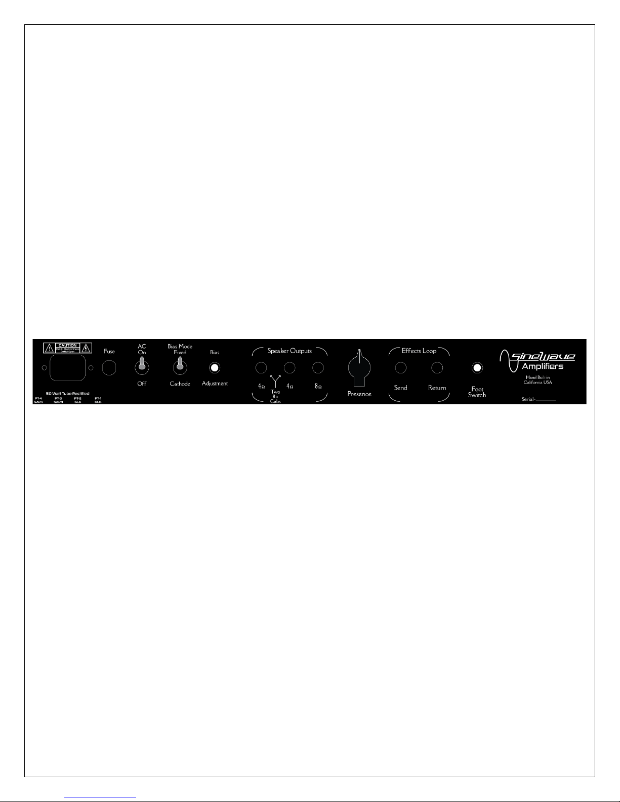
Back Panel Functions
- AC Input Receptacle - Input only supplied AC cord or one specified to your countries specific
input voltages and pin-outs. Amplifiers are designed for voltages of 100VAC, 120VAC, 220VAC,
230VAC, & 240VAC and will operate at both 50 and 60 cycles.
- Fuse Only use factory installed Slow-Blow fuse rated at the correct amps.-
- AC On/Off Switch –This switch will allow the amp to be powered up and will also supply
power to the tubes. When Turning the amp off we recommend that the standby switch be left in
the on position and the power switch be turned to the OFF position.
- Bias Mode Switch and Bias Adjustment Control - This part of the power section controls
the operating range of the power tubes. Ultimately this can affect the feel of the amp plus
change the harmonic content and breakup of the power section. This control circuit can only be
installed on 20 and 50 watt amplifiers. Please contact us on how to bias the amplifier.
oFixed Mode This option leaves the bias point of the power section up to the player to-
set. There is a recommended range to follow to not burn out the tubes (please refer to
bias range below). A digital multimeter will be needed to adjust this. This mode will
allow the power section greater range in output power leading to higher levels of clean

headroom. However the bias can be set to a “hotter” sweet spot and create natural
power stage breakup. The Bias adjustment Control will need a flat head screwdriver to
adjust. Just stick the driver into the controls center hole.
oCathode Mode This option is a preset circuit configuration that will allow the output-
section to have more natural breakup and harmonic content. The overall headroom of
the power section will be reduced and the amp will seem to get louder. This option is
going to have more “sag” then the fixed mode and will lend itself to more of a “vintage”
feel.A note to this mode Since there is no need to adjust the bias tubes can be:
swapped in and out of the power stage. Can be very handy if a tube dies during
rehearsal or a live event. Simply pull the installed tubes and install a new set. No
need to worry about bias levels.
- Speaker Output Jacks - There are multiple impedance options here for speaker
configurations. There is a single 8 ohm output and two 4 ohm outputs. The dual 4 ohm outputs
are a parallel option for the use of the 8 ohm speaker cabinets.
oNever operate the amplifier without speakers plugged in. Damage can
occur to both the output transformers and output tubes.
- - Adjusts the contour of high-frequency response. The high-frequency
Presence Control
response will increase as you advance the control clockwise. The Control will also increase the
“stringiness” of the guitar signal the higher it is turned up.
- Effects Loop -The effects loop is a passive insertion point after the Master control and inputs
any effects post preamp and pre power stage. We don’t recommend installing any type of OD or
boost pedal into the effects loop. You will find the most success with time based effects such as
delays, reverbs, tremolo’s, or even loop stations.
oPlug your buffered effects into this point. The Master volume willEffect Send -
control signal into the effects.
oThe effect Chain will reintroduce signal back into the amplifier here.Effect Return -
We recommend the use of another buffered pedal at this point as well.
- Foot-Switch Input - Insert stereo ¼” cable and connect to footswitch for control of T.S.Bypass
and Overdrive options.
Fuse Options:
- 100VAC:
o50 Watt 2.5 amp Slow-Blow
o100 Watt 3.2 amp Slow-Blow
- 120VAC
o50 Watt 2.5 amp Slow-Blow
o100 Watt 3.2 amp Slow-Blow
- 220VAC, 230VAC, & 240VAC
o50 Watt 1.6 amp Slow-Blow
o100 Watt 2.5 amp Slow-Blow
*Power Stage Tube Options: Only install tubes that your amplifier was built for. Installing
different tubes will lead to failure of the tubes and damage the amplifier.
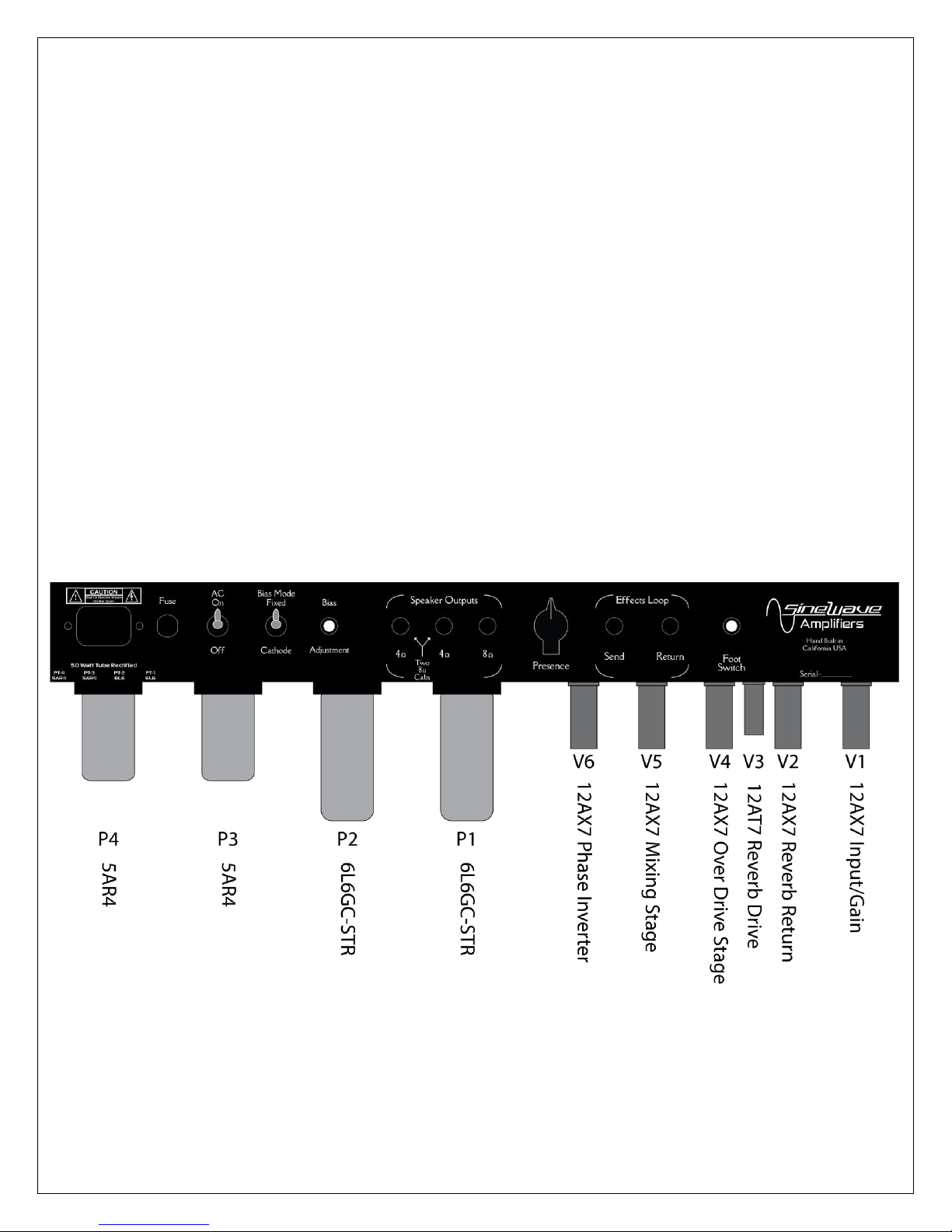
Tube Layout
Standard Tube Compliment Is a 50 Watt Dual Tube Rectified Power Section.
Optional El-34/6CA7
Optional 20Watt 2x6V6 Dual Tube Rectified Options

And
100 Watt (6L6 or El-34/6CA7)Solid State Rectification
Are Available
P3 & P4 Become 6L6GC-STR For 100 Watt Power Sections
Please Contact Support If you Have Any Questions Regarding Tubes Or Service
*Warning*
There Are No Serviceable Parts Inside!
Please Refer To Qualified Personal For Service.
Thanks For Purchasing!
SineWaveAmps.com
707-695-2322

For Service
Info@sinewaveamps.com
Table of contents
Popular Amplifier manuals by other brands


Peavey
Peavey UMA 150T II user guide

Signal Audio Workshop
Signal Audio Workshop CH-2 owner's manual

DigiTenna
DigiTenna DT-RAMP20-2 instructions

Texas Instruments
Texas Instruments LMP7731 manual

Constellation audio
Constellation audio Hercules II owner's manual

Clever Acoustics
Clever Acoustics MA 4040 user manual