Clever Acoustics MA 4040 User manual

MA 4040 160W
4 Zone Mixer Amplier
User Manual
Order code: CRAM32
MA 4040 Mixer Amplier
Z1
VOL
MUTE
Z3
Z2
Z4
CH 1
0
1
2
3
456
7
8
9
10
-10 +10
-10 +10
-10 +10
Z1
VOL
MUTE
Z3
Z2
Z4
CH 2
0
1
2
3
456
7
8
9
10
-10 +10
-10 +10
-10 +10
Z1
VOL
MUTE
Z3
Z2
Z4
CH 3
0
1
2
3
456
7
8
9
10
-10 +10
-10 +10
-10 +10
Z1
VOL
MUTE
Z3
Z2
Z4
CH 4
0
1
2
3
456
7
8
9
10
-10 +10
-10 +10
-10 +10
Z1
VOL
MUTE
Z3
Z2
Z4
CH 5
-10 +10
-10 +10
-10 +10
010
PHONE
PHONE
VOLUME
MONITOR
VOLUME
010
VOLUME
ZONE 3
MONITOR
0
1
2
3
456
7
8
9
10
ZONE 1 ZONE 2
ZONE 4
VOLUME
MONITOR
0
1
2
3
456
7
8
9
10
VOLUME
MONITOR
0
1
2
3
456
7
8
9
10
VOLUME
MONITOR
0
1
2
3
456
7
8
9
10
ON
OFF
POWER
POWER INPUT:
110-240V~50/60Hz
110-120V~60Hz - FUSE: T6.3A 250V
220-240V~50/60Hz - FUSE: T3.15A 250V
110-120V~ 220-240V~
SERIAL NUMBER
MONITOR
LINE OUTPUT
G +
MONITOR
1W 8Ω
PRIORITY
– +
TEL PAGING
TEL
VOLUME
LINE OUT - BAL/UNBAL POWER AMP OUTPUT
COM 4Ω 8Ω 25V 70V 100VZONE 1
ZONE
COM GNDHOT
CH4
LINE
CH3
PHANTOM
LINE MIC
CH2
CH1
CH5
LINE
L
R
PHANTOM
LINE MIC
G – +
LINE OUT - BAL/UNBAL POWER AMP OUTPUT
COM 4Ω 8Ω 25V 70V 100VZONE 2 G – +
LINE OUT - BAL/UNBAL POWER AMP OUTPUT
COM 4Ω 8Ω 25V 70V 100VZONE 3 G – +
LINE OUT - BAL/UNBAL POWER AMP OUTPUT
COM 4Ω 8Ω 25V 70V 100VZONE 4 G – +
0
1
2
3
456
7
8
9
10
WARNING: TO REDUCE THE RISK OF FIRE OR ELECTRIC SHOCK.
DO NOT EXPOSE THIS EQUIPMENT TO RAIN OR MOISTURE
CAUTION
RISK OF ELECTRIC SHOCK
DO NOT OPEN. NO USER
SERVICABLE PARTS INSIDE
www.cleveracoustics.co.uk
PHANTOM
LINE MIC
POWER CONSUMPTION (max.): 180W
LF
HF
GAIN
LF
HF
GAIN
LF
HF
GAIN
LF
HF
GAIN
LF
HF
GAIN

www.cleveracoustics.co.uk MA 4040 160W Mixer Amplier User Manual 2
Safety advice
WARNING
FOR YOUR OWN SAFETY, PLEASE READ THIS USER MANUAL
CAREFULLY BEFORE YOUR INITIAL START-UP!
• Beforeyourinitialstart-up,pleasemakesurethatthereisnodamagecausedduringtransportation.
• Shouldtherebeanydamage,consultyourdealeranddonotusetheequipment.
• Tomaintaintheequipmentingoodworkingconditionandtoensuresafeoperation,itisnecessary
fortheusertofollowthesafetyinstructionsandwarningnoteswritteninthismanual.
• Pleasenotethatdamagescausedbyusermodicationstothisequipmentarenotsubjecttowarranty.
IMPORTANT:
The manufacturer will not accept liability for any resulting damages caused by the non-observance
of this manual or any unauthorised modication to the equipment.
OPERATING DETERMINATIONS
Ifthisequipmentisoperatedinanyotherway,thanthosedescribedinthismanual,theproductmaysufferdamageand
thewarrantybecomesvoid.Incorrectoperationmayleadtodangere.g:short-circuit,burnsandelectricshocksetc.
Donotendangeryourownsafetyandthesafetyofothers!
Incorrectinstallationorusecancauseseriousdamagetopeopleand/orproperty.
• Neverletthepowercablecomeintocontactwithother
cables.Handlethepowercableandallmainsvoltage
connectionswithparticularcaution!
• Neverremovewarningorinformativelabelsfromtheunit.
• Donotopentheequipmentanddonotmodifytheunit.
• Donotswitchtheequipmentonandoffinshortintervals,
asthiswillreducethesystem’slife.
• Onlyusetheequipmentindoors.
• Donotexposetoammablesources,liquidsorgases.
• Alwaysdisconnectthepowerfromthemainswhen
equipmentisnotinuseorbeforecleaning!Onlyhandle
thepower-cablebytheplug.Neverpullouttheplugby
pullingthepower-cable.
• Makesurethattheavailablevoltage
isbetween240V,50HzAC.
• Makesurethatthepowercableisnevercrimpedor
damaged.Checktheequipmentandthepowercable
periodically.
• Iftheequipmentisdroppedordamaged,disconnectthe
mainspowersupplyimmediatelyandhaveaqualied
engineerinspecttheequipmentbeforeoperatingagain.
• Iftheequipmenthasbeenexposedtodrastic
temperatureuctuation(e.g.aftertransportation),
donotconnectpowerorswitchitonimmediately.
Thearisingcondensationmightdamagetheequipment.
Leavetheequipmentswitchedoffuntilithasreached
roomtemperature.
• Ifyourproductfailstofunctioncorrectly,stopuse
immediately.Packtheunitsecurely(preferablyinthe
originalpackingmaterial),andreturnittoyourProlight
dealerforservice.
• Onlyusefusesofsametypeandrating.
• Repairs,servicingandpowerconnectionmustonlybe
carriedoutbyaqualiedtechnician.THISUNITCONTAINS
NOUSERSERVICEABLEPARTS.
• WARRANTY:Threeyearsfromdateofpurchase.
CAUTION!
KEEP THIS EQUIPMENT
AWAY FROM RAIN,
MOISTURE AND LIQUIDS
CAUTION!
TAKE CARE USING
THIS EQUIPMENT!
HIGH VOLTAGE-RISK
OF ELECTRIC SHOCK!!

www.cleveracoustics.co.uk MA 4040 160W Mixer Amplier User Manual 3
Product overview & technical specications
TheMA40404ZoneMixerAmplierisidealforsystemswheremultiplezonesarerequired.Designedforuse
invenuessuchasschools,churches,entertainmentvenuesorcommercialbuildings,theMA4040offersmulti
zoneaudioroutingcoupledwithfourindependent40Wrmsampliers.TheMA40404zonemixeramplierhas
veinputchannels,eachwithselectableindependentoutputrouting,inputgain,treblebassandvolumecontrols.
Inputchannels1thru3areviaXLR/Jackcombosockets,eachwithLine/Mic/Mic+Phantomselection,input
channels4&5areviastereolineRCAphonolevelinputs.
FouroutputzoneseachfeatureLEDVUindicators,monitorselectionandvolumecontrolswithoutputsforline
level,lowimpedance(4-8Ω)andconstantvoltagespeakersystems(25V,75V&100V).Theon-boardmonitor
facility,selectableforeachzoneoutputfeaturesbothalinelevelaudioand1W8Ωloudspeakeroutputsuitablefor
drivingaloudspeakerlocaltotheMA4040zonemixer.
•Fouroutputzoneseachwithlevelcontrolandmonitorselection
•Fourindependent40Wrmsamplifiersoutputtingto4-8Ωor25,70,100V
•Fiveinputchannels:
Channels1-3areviaXLR/Jackcombosockets,
eachwithLine/Mic/Mic+Phantomselection(48V)
Channels4and5areviaphono(RCA)stereolinelevelinputs
•3U,19”rackmountchassis
•Inputgain,treble,bassandlevelcontrols
•Selectableoutputroutingforallinputchannels
•MonitorfunctionwithlevelcontrolandLEDVUmeter
•Outputformonitorloudspeaker:1W,8Ω
•Headphoneoutputwithlevelcontrol
•Telephone/paginginput(zoneselectable)withadjustablelevel
•Prioritycontactformusicmutefacility(CH4and5mute,CH1-3priority)
•VOXoperatedpriorityforTELinput
•CH1inputautomaticVOXpriority(internaljumperforpriorityoverride)
•TelephoneandMIC1(musicmutefacility)
•Inputchannelmuteswitchesonfrontpanel
•LinelevelMIXoutput
•Temperaturecontrolled,variablespeedfancooling
MA 4040 160W 4 Zone Mixer Amplier
MA 4040 Mixer Amplier
Z1
VOL
MUTE
Z3
Z2
Z4
CH 1
0
1
2
3
456
7
8
9
10
-10 +10
-10 +10
-10 +10
Z1
VOL
MUTE
Z3
Z2
Z4
CH 2
0
1
2
3
456
7
8
9
10
-10 +10
-10 +10
-10 +10
Z1
VOL
MUTE
Z3
Z2
Z4
CH 3
0
1
2
3
456
7
8
9
10
-10 +10
-10 +10
-10 +10
Z1
VOL
MUTE
Z3
Z2
Z4
CH 4
0
1
2
3
456
7
8
9
10
-10 +10
-10 +10
-10 +10
Z1
VOL
MUTE
Z3
Z2
Z4
CH 5
-10 +10
-10 +10
-10 +10
010
PHONE
PHONE
VOLUME
MONITOR
VOLUME
010
VOLUME
ZONE 3
MONITOR
0
1
2
3
456
7
8
9
10
ZONE 1 ZONE 2
ZONE 4
VOLUME
MONITOR
0
1
2
3
456
7
8
9
10
VOLUME
MONITOR
0
1
2
3
456
7
8
9
10
VOLUME
MONITOR
0
1
2
3
456
7
8
9
10
ON
OFF
POWER
POWER INPUT:
110-240V~50/60Hz
110-120V~60Hz - FUSE: T6.3A 250V
220-240V~50/60Hz - FUSE: T3.15A 250V
110-120V~ 220-240V~
SERIAL NUMBER
MONITOR
LINE OUTPUT
G +
MONITOR
1W 8Ω
PRIORITY
– +
TEL PAGING
TEL
VOLUME
LINE OUT - BAL/UNBAL POWER AMP OUTPUT
COM 4Ω 8Ω 25V 70V 100VZONE 1
ZONE
COM GNDHOT
CH4
LINE
CH3
PHANTOM
LINE MIC
CH2
CH1
CH5
LINE
L
R
PHANTOM
LINE MIC
G – +
LINE OUT - BAL/UNBAL POWER AMP OUTPUT
COM 4Ω 8Ω 25V 70V 100VZONE 2 G – +
LINE OUT - BAL/UNBAL POWER AMP OUTPUT
COM 4Ω 8Ω 25V 70V 100VZONE 3 G – +
LINE OUT - BAL/UNBAL POWER AMP OUTPUT
COM 4Ω 8Ω 25V 70V 100VZONE 4 G – +
0
1
2
3
456
7
8
9
10
WARNING: TO REDUCE THE RISK OF FIRE OR ELECTRIC SHOCK.
DO NOT EXPOSE THIS EQUIPMENT TO RAIN OR MOISTURE
CAUTION
RISK OF ELECTRIC SHOCK
DO NOT OPEN. NO USER
SERVICABLE PARTS INSIDE
www.cleveracoustics.co.uk
PHANTOM
LINE MIC
POWER CONSUMPTION (max.): 180W
LF
HF
GAIN
LF
HF
GAIN
LF
HF
GAIN
LF
HF
GAIN
LF
HF
GAIN
Specications MA 4040 160W Mixer Amplier
Poweroutput 4x40Wrms(4x90Wpeak)
Speakeroutputs 25V,70V,100Vand4-8Ω
Sensitivity -CH1–3:-42dB/-38dB
(Micbal./unbal./),-26dB/-20dB
(Linebal./unbal.)
-CH4:-10dB
-CH5:0dB
Frequencyresponse 50Hz-17kHz(±3dB)
Tonecontrol ±10dB-100Hz/±10dB-10kHz
(bass/treble)
S/Nratio >55dB(Mic),>60dB(Line)
THD <1%(@1kHz1Woutput)
Powerconsumption 180W(max.)
Powersupply 110-240V~50/60HzAC
Fuse T3.15A250V
Dimensions 135x484x310mm
Weight 15kg
Ordercode CRAM32
Z1
Z3
Z2
Z4
CH 1
0
1
2
3
456
7
8
9
10
-10 +10
-10 +10
-10 +10
Z1
Z3
Z2
Z4
CH 2
0
1
2
3
456
7
8
9
10
-10 +10
-10 +10
-10 +10
Z1
Z3
Z2
Z4
CH 3
0
1
2
3
456
7
8
9
10
-10 +10
-10 +10
-10 +10
Z1
Z3
Z2
Z4
CH 4
0
1
2
3
456
7
8
9
10
-10 +10
-10 +10
-10 +10
Z1
Z3
Z2
Z4
CH 5
0
1
2
3
456
7
8
9
100
1
2
3
456
7
8
9
10
-10 +10
-10 +10
-10 +10
010
PHONE
PHONE
VOLUME
MONITOR
VOLUME
010
VOLUME
ZONE 3
MONITOR
0
1
2
3
456
7
8
9
10
ZONE 1 ZONE 2
ZONE 4
VOLUME
MONITOR
0
1
2
3
456
7
8
9
10
VOLUME
MONITOR
0
1
2
3
456
7
8
9
10
VOLUME
MONITOR
0
1
2
3
456
7
8
9
10
ON
OFF
POWER
LF
HF
GAIN
LF
HF
GAIN
LF
HF
GAIN
LF
HF
GAIN
LF
HF
GAIN
MUTE MUTE MUTE MUTEMUTE
VOL VOL VOL VOL VOL
MA 4040 Mixer Amplier
135mm
484mm 310mm

www.cleveracoustics.co.uk MA 4040 160W Mixer Amplier User Manual 4
Panel & connection identication
01-Gaincontrol
02-HFlevelcontrol
03-LFlevelcontrol
04-Muteswitch
05-MuteLED
06-Inputchannellevelcontrol
07-Zoneselectionswitches
08-Headphonelevelcontrol
09-Headphoneoutput
10-LEDVUoutputmeter
11-Monitorlevelcontrol
12-Zoneoutputlevelcontrol
13-Monitoroutputselector
14-PowerLED
15-Powerswitch
16-Coolingfan
17-ACmainspowerinput
18-ACmainsfuse
19-ACvoltageselector
20-Monitor(MIX)lineoutput
21-Monitorloudspeakeroutput
(1W8Ω)
22-Prioritycontrolterminals
23-Telephone/paginginput(TEL)
24-Telephone/paginginput
zoneselection&volumecontrol
25-StereoLINEinputs
26-MonoMIC/LINEinputs
27-Inputsensitivityandphantom
powercontrol
28-Balancedlinelevelzoneoutputs
29-Poweramplieroutputs
MA 4040 Mixer Amplier
Z1
VOL
MUTE
Z3
Z2
Z4
CH 1
0
1
2
3
456
7
8
9
10
-10 +10
-10 +10
-10 +10
Z1
VOL
MUTE
Z3
Z2
Z4
CH 2
0
1
2
3
456
7
8
9
10
-10 +10
-10 +10
-10 +10
Z1
VOL
MUTE
Z3
Z2
Z4
CH 3
0
1
2
3
456
7
8
9
10
-10 +10
-10 +10
-10 +10
Z1
VOL
MUTE
Z3
Z2
Z4
CH 4
0
1
2
3
456
7
8
9
10
-10 +10
-10 +10
-10 +10
Z1
VOL
MUTE
Z3
Z2
Z4
CH 5
-10 +10
-10 +10
-10 +10
010
PHONE
PHONE
VOLUME
MONITOR
VOLUME
010
VOLUME
ZONE 3
MONITOR
0
1
2
3
456
7
8
9
10
ZONE 1 ZONE 2
ZONE 4
VOLUME
MONITOR
0
1
2
3
456
7
8
9
10
VOLUME
MONITOR
0
1
2
3
456
7
8
9
10
VOLUME
MONITOR
0
1
2
3
456
7
8
9
10
ON
OFF
POWER
POWER INPUT:
110-240V~50/60Hz
110-120V~60Hz - FUSE: T6.3A 250V
220-240V~50/60Hz - FUSE: T3.15A 250V
110-120V~ 220-240V~
SERIAL NUMBER
MONITOR
LINE OUTPUT
G +
MONITOR
1W 8Ω
PRIORITY
– +
TEL PAGING
TEL
VOLUME
LINE OUT - BAL/UNBAL POWER AMP OUTPUT
COM 4Ω 8Ω 25V 70V 100VZONE 1
ZONE
COM GNDHOT
CH4
LINE
CH3
PHANTOM
LINE MIC
CH2
CH1
CH5
LINE
L
R
PHANTOM
LINE MIC
G – +
LINE OUT - BAL/UNBAL POWER AMP OUTPUT
COM 4Ω 8Ω 25V 70V 100VZONE 2 G – +
LINE OUT - BAL/UNBAL POWER AMP OUTPUT
COM 4Ω 8Ω 25V 70V 100VZONE 3 G – +
LINE OUT - BAL/UNBAL POWER AMP OUTPUT
COM 4Ω 8Ω 25V 70V 100VZONE 4 G – +
0
1
2
3
456
7
8
9
10
WARNING: TO REDUCE THE RISK OF FIRE OR ELECTRIC SHOCK.
DO NOT EXPOSE THIS EQUIPMENT TO RAIN OR MOISTURE
CAUTION
RISK OF ELECTRIC SHOCK
DO NOT OPEN. NO USER
SERVICABLE PARTS INSIDE
www.cleveracoustics.co.uk
PHANTOM
LINE MIC
POWER CONSUMPTION (max.): 180W
LF
HF
GAIN
LF
HF
GAIN
LF
HF
GAIN
LF
HF
GAIN
LF
HF
GAIN
16 17 18 25 26 27 28 29
19 20 21 22 23 24 26 27
MA 4040 Mixer Amplier
Z1
VOL
MUTE
Z3
Z2
Z4
CH 1
0
1
2
3
456
7
8
9
10
-10 +10
-10 +10
-10 +10
Z1
VOL
MUTE
Z3
Z2
Z4
CH 2
0
1
2
3
456
7
8
9
10
-10 +10
-10 +10
-10 +10
Z1
VOL
MUTE
Z3
Z2
Z4
CH 3
0
1
2
3
456
7
8
9
10
-10 +10
-10 +10
-10 +10
Z1
VOL
MUTE
Z3
Z2
Z4
CH 4
0
1
2
3
456
7
8
9
10
-10 +10
-10 +10
-10 +10
Z1
VOL
MUTE
Z3
Z2
Z4
CH 5
-10 +10
-10 +10
-10 +10
010
PHONE
PHONE
VOLUME
MONITOR
VOLUME
010
VOLUME
ZONE 3
MONITOR
0
1
2
3
456
7
8
9
10
ZONE 1 ZONE 2
ZONE 4
VOLUME
MONITOR
0
1
2
3
456
7
8
9
10
VOLUME
MONITOR
0
1
2
3
456
7
8
9
10
VOLUME
MONITOR
0
1
2
3
456
7
8
9
10
ON
OFF
POWER
POWER INPUT:
110-240V~50/60Hz
110-120V~60Hz - FUSE: T6.3A 250V
220-240V~50/60Hz - FUSE: T3.15A 250V
110-120V~ 220-240V~
SERIAL NUMBER
MONITOR
LINE OUTPUT
G +
MONITOR
1W 8Ω
PRIORITY
– +
TEL PAGING
TEL
VOLUME
LINE OUT - BAL/UNBAL POWER AMP OUTPUT
COM 4Ω 8Ω 25V 70V 100VZONE 1
ZONE
COM GNDHOT
CH4
LINE
CH3
PHANTOM
LINE MIC
CH2
CH1
CH5
LINE
L
R
PHANTOM
LINE MIC
G – +
LINE OUT - BAL/UNBAL POWER AMP OUTPUT
COM 4Ω 8Ω 25V 70V 100VZONE 2 G – +
LINE OUT - BAL/UNBAL POWER AMP OUTPUT
COM 4Ω 8Ω 25V 70V 100VZONE 3 G – +
LINE OUT - BAL/UNBAL POWER AMP OUTPUT
COM 4Ω 8Ω 25V 70V 100VZONE 4 G – +
0
1
2
3
456
7
8
9
10
WARNING: TO REDUCE THE RISK OF FIRE OR ELECTRIC SHOCK.
DO NOT EXPOSE THIS EQUIPMENT TO RAIN OR MOISTURE
CAUTION
RISK OF ELECTRIC SHOCK
DO NOT OPEN. NO USER
SERVICABLE PARTS INSIDE
www.cleveracoustics.co.uk
PHANTOM
LINE MIC
POWER CONSUMPTION (max.): 180W
LF
HF
GAIN
LF
HF
GAIN
LF
HF
GAIN
LF
HF
GAIN
LF
HF
GAIN
71 2 3 6 9 11 13 15
810 10 12 144 5

www.cleveracoustics.co.uk MA 4040 160W Mixer Amplier User Manual 5
Layout identication:
1. Gain control:
Thegaincontrolisusedtoadjusttheinputgain(level)foreachofthezonemixersinputchannels.Turn
thelevelcontrolanticlockwisetothelowestsetting,orturnclockwisetoadjusttothehighestsetting.
Adjustmentsshouldbemadegraduallytoavoidanysuddenchangestotheaudiooutput.Iftheaudio
sourceappearstosounddistorted,areductioningainmayberequired.
2. HF level control:
Duringinitialsetupthehighfrequencytoneadjustmentshouldbesettothezeropoint(12’o’clock
position).Turnthelevelcontrolanticlockwisetoreducethehighfrequencytones,orturnclockwise
toadjusttheincreasethehighfrequencytones.Adjustmentsshouldbemadegraduallytoavoidany
suddenchangestotheaudiooutput.
3. LF level control:
Duringinitialsetupthelowfrequencytoneadjustmentshouldbesettothezeropoint(12’o’clock
position).Turnthelevelcontrolanticlockwisetoreducethelowfrequencytones,orturnclockwise
toadjusttheincreasethehighfrequencytones.Adjustmentsshouldbemadegraduallytoavoidany
suddenchangestotheaudiooutput.
4. Mute switch:
Pressthemuteswitchtomute(silence)theselectedinputchannel.
5. Mute LED:
ThemuteLEDprovidesavisualindicationwhentheinputchannelisinmutestatus.
6. Input channel level control:
Thegaincontrolisusedtoadjusttheinputgain(level)foreachofthezonemixersinputchannels.Turn
thelevelcontrolanticlockwisetothelowestsetting,orturnclockwisetoadjusttothehighestsetting.
Adjustmentsshouldbemadegraduallytoavoidanysuddenchangestotheaudiooutput.Iftheaudio
sourceappearstosounddistorted,areductioningainmayberequired.Theinputchannellevelcontrol
adjuststheleveloftheselectedinputchannelwithinthemainmix.
7. Zone selection switches:
Eachoftheveinputchannelsmayberoutedtoanyofthefouroutputzones.
PresstheswitchtotheINpositiontoroutetheselectedinputchanneltothechosenoutputzone.
8. Headphone level control:
Theheadphoneoutputvolumeisadjustable.Turnthelevelcontrolanticlockwisetothelowestsetting,
orturnclockwisetoadjusttothehighestsetting.
9. Headphone output:
Utilisingastandard3.5mmstereojacksocket,theheadphoneoutputisusedalongsidethemonitor
functiontochecktheoutputofindividualoutputzones.Ifnoneoftheoutputzonesareselectedusing
themonitorselectionswitches,theheadphoneoutputwillbemuted.
Operating instructions

www.cleveracoustics.co.uk MA 4040 160W Mixer Amplier User Manual 6
Operating instructions
10. LED VU output meter:
Theoutputtoeachzonemaybemonitoredvisuallyontheamplier.TheVUmeterhasthreegreen
stages,followedbyamberandthenred.Careshouldbetakentoavoidthesignallevelreachingthe
amberorredzonesasthiswillindicateaclippedsignalwithinthezonemixer.Inthisinstance,theInput
Channeland/orZoneOutputLevelshouldbereduced.
11. Monitor level control:
Themonitoroutputvolumeisadjustable.Turnthelevelcontrolanticlockwisetothelowestsetting,
orturnclockwisetoadjusttothehighestsetting.Thisisusedtocontrolthevolumeforthe1W8Ω
loudspeakeroutputontherearpanelofthezonemixer.
12. Zone output level control:
Themastervolumecontrolaffectsallaudiosourceswithintheamplier,routedtotheselectedzone.
Turnthelevelcontrolanticlockwisetothelowestsetting,orturnclockwisetoadjusttheoveralloutput
tothehighestsetting.Adjustmentsshouldbemadegraduallytoavoidanysuddenchangestotheaudio
output.
13. Monitor output selector:
Torouteoneoftheoutputzonestothemonitor&headphoneoutputs,presstheMonitorselection
button.ThemonitoroutputvolumecanthenbeadjustedusingtheMonitorVolumeControl.
14. Power LED:
ThePowerLEDwillilluminatetoindicatethezonemixerispoweredon.IfthepowerLEDisnot
illuminated,checkrstthepositionoftheon/offswitchandthencheckthemains(includingfuse)orDC
powersupply.
15. Power switch:
On/Offcontrolforthezoneamplier.Note:Theon/offpowerswitchdoesnothaveanycontroloverthe
24VDCpowerinput.
16. Cooling fan:
TheMA4040isfancooled.Thecoolingfanwillstartwhentheinternaltemperaturesensorreaches
50°C.Thefanspeedwillvaryaccordingtotheinternaltemperatureoftheamplier.Donotblockor
obstructthefanportontherearpanelortheairventsonthetoporsidepanels.
17. AC mains power input:
Beforeconnectingtheampliertothelocalmainsvoltageoutletshouldbecheckedtoensurethe
availablesupplyis240V~AC50Hz.ThisproductisCLASS1andrequiresaprotectivemainsearthtobe
connectedatalltimes.DONOTremoveordisconnecttheearth.
18. AC mains fuse:
Disconnectfromthemainspowersupplybeforeattemptingtoreplacethemainsfuse.Replacement
mainsfusesmustbethesameratingastheoriginal.T3.15AL250Vfor220-240VACmainssupplyor
T6.3AL250Vfor110-120VACmainssupply.

www.cleveracoustics.co.uk MA 4040 160W Mixer Amplier User Manual 7
Operating instructions
19. AC voltage selector:
TheMA4040zonemixerfeaturesadualvoltagemainsinput.Disconnecttheunitfromthemains
voltagepowersupplybeforeattemptingtochangethemainsinputvoltage.Careshouldbetakento
selecttheappropriatemainsinputvoltagetomatchthatofthemainssupplyvoltage.
20. Monitor (MIX) line output:
Themonitorlineoutputcanbeusedtofeedexternalamplicationorrecordingequipment.TheMonitor
lineoutputprovidesanunbalanced(4V)signalfollowingthefrontpanel“monitor”selection.Ifseveral
zonesareselected,theoutputwillbeamixedsignalofalltheselectedzones.
21. Monitor loudspeaker output (1W 8Ω):
Auxiliaryconnectionfortheconnectionofasmallexternalloudspeakerforlocalmonitoringpurposes.
Thenominaloutputis1Wwithaminimumimpedanceof8Ω.Ifnoneoftheoutputzonesareselected
usingthemonitorselectionswitches,theheadphoneoutputwillbemuted.
22. Priority control terminals (Music Mute):
Whentheterminalsareshort-circuitedbymeansofaswitchorrelay(ierealarmpanel),input
channelsCH4andCH5willbemuted,leavinginputchannelsCH1,CH2andCH3withprioritystatus.
Note:TheTELinputcarrieshighestpriorityandwilloverridethePriority(MusicMute)function.
23. Telephone/paging input (TEL):
Foremergencypaging,theMA4040isequippedwithabalancedaudioTELinput,activated
automaticallyupontheMA4040detectinganaudiosignalpresentontheTELinputterminals.The
inputcarriesthehighestpriorityandwilloverrideallotherinputs&priorityfunctionsontheamplier.
24. Telephone/paging input zone selection & volume control:
TheTELinputfeatureszonecontrolandinputvolumecontrol.ToroutetheTELsignaltoadesired
outputzone,movethecorrespondingDIPswitchtothedown(ON)position.Theinputvolumeforthe
TELsignalmaybecontrolledbytherecessedvolumecontrolpotentiometer.Formostapplications,it
maybebestpracticetosettheminimumpossibleleveltopreventunwantedactivationofthepriority
input.Turnthepotentiometerclockwisetoincreasethevolume.
25. Stereo LINE inputs:
AstereoaudioinputisprovidedforsourcessuchasFMTuners,CDPlayersorMP3Players.Theinput
featuresapairofunbalancedphono(RCA)inputssuitableforlinelevelaudioinput.
26. Mono MIC/LINE inputs:
Channels1,2&3allfeaturemonoaudioinputs,eachwithselectorforusewithMIC/MIC+Phantom/
Linesignals.TheaudioinputisdesignedtoacceptabalancedaudiosignalviaXLRor6.35mm(¼”)
TRSjack.
Channel1featuresautomaticpriorityoverrideoverchannels2,3and4.Ifthisfeatureisnotrequired,
theusermustrefertoaservicetechnicianwhowillbeabletofollowtheinstructionsonpage9to
defeatthevoicepriorityfunction.

www.cleveracoustics.co.uk MA 4040 160W Mixer Amplier User Manual 8
Operating instructions
27. Input sensitivity and phantom power control:
Channels1,2,3&4eachfeatureswitchableinputsforusewithMIC/MIC+Phantom/Linesignals.The
MICposititionisdesignedtoacceptabalanced,lowlevelsignalfromastandarddynamicmicrophone
(5mV/1kΩ).ThePHANTOMpositionisdesignedtoprovide15VphantompoweracrossXLRpins2&3
forusewithcondensermicrophones.TheLINEpositionisforusewithlinelevelsourcessuchasradio
microphonereceivers,CDplayersandFMtuners(100mV/10kΩ),thesignalmaybeinputtedusing
eitherthebalancedXLRorbalancedTRS6.35mm(¼”)jack.
28. Balanced line level zone outputs:
TheMA4040featuresfour,independentzoneoutputseachutilisingbarrierstripterminalsforthe
balancedaudiooutput(1.7V).Thelineleveloutputsmaybeusedtofeedsignaltoexternalamplication
whereadditionalamplicationisrequired.Iftheamplierconnectedonlyrequiresanunbalancedsignal,
theoutputcontacts“+”and“G”shouldbeused.
29. Power amplier outputs:
EachofthefouroutputzonesontheMA4040featuresbothlowimpedanceandconstantvoltage
loudspeakeroutputs.Eachoutputzonemaybeusedtooutputintoeitherlowimpedance(4-8Ω)or
constantvoltage(25V,70V,100V).Donotusemorethanonepairofoutputterminalsonanyone
outputzone.Careshouldbetakenwhenconnectingtotheoutputstoensuretheloadimpedanceis
abovetheminimumloadspeciedfortheoutput.
Power on/off procedure:
Priortomakinganyconnectiontothemainspoweroraudioinputs/outputs,turnalllevelcontrols
counterclockwisetothe“0”positionandalltone(equaliser)controlstothemid(zero)point.Deselect
allmonitorandzoneselectioncontrols.
Switchonthezonemixerandanyaudiosources(MP3players,CDplayers,Microphonesetc)before
poweringthesystemsamplierON.Thelastproducttobeswitchedonshouldbethepower/slave
amplierstopreventanyunwantednoiseorpotentialdamagetospeakersorampliers.Ifyouwish
topoweroffthesystem,turntheamplier’smastervolumecontrolcounterclockwisetothe“0”
positionbeforeswitchingtheamplierOFFbeforeanyaudiosourcesareswitchedoff.Byfollowingthis
procedureitwillpreventacousticshockstothespeakersorpotentialdamagetosystemcomponents.
Afterconnectingallaudiosourcesandpoweringonthesystem,adjustthelevelofeachaudioinput,
selectthezoneroutinginordertoachievethedesired“mix”foreachzone.Careshouldbetaken
towhenadjustingmicrophoneinputvolumesandthemastervolume,adjustbothoftheseinsmall
increment’stoavoidfeedback(howlaround).Thegoalistoachieveaclearbalancebetweenmusicand
voiceensuringannouncementscanbeclearlyheard.

www.cleveracoustics.co.uk MA 4040 160W Mixer Amplier User Manual 9
Operating instructions
MIC priority:
DuringnormaloperationtheMA4040featurespriorityforMIC1overtheothermicrophoneandline
inputs.Forcertainapplications,theinstallationengineermayneedtodefeattheMIC1priorityfunction.
Inordertodothis,theproductmustbefullydisconnectedfromanyACorDCpowersources,and
disconnectedfromallinputs/outputs.
Removethe15screwsfromtheoutercasingasperthediagrambelowandkeepinasafelocation.
Removetheuppercasingandplacetooneside.LocatethePCBtowardstherearoftheunitaspictured
below.Carefullymovethejumperfromthe"ON"positiontothe"OFF"position.Rettheoutercasing,
takingcaretoavoiddamagingtheunit.Retallofthescrewstofullysecuretheoutercasing.
TopofMixer
RearofMixer
Side1of
Mixer
Side2of
Mixer

www.cleveracoustics.co.uk MA 4040 160W Mixer Amplier User Manual 10
Typical panel connections
C ontact
"V O IC E P R IO R
Mains
Recorder
PAAmplier
Recorder
CDPlayer
AM/FMTuner
DesktopMic
Microphone
Monitor
Speaker
Amplier
Contact
“VoicePriority”
Horn
speaker
Column
speaker
Speaker

www.cleveracoustics.co.uk MA 4040 160W Mixer Amplier User Manual 11
Rack installation:
TheMAseriesisrackmountable.Therackyouuseshouldbeadoubledoorrackwhereyoucanopen
thefrontandrearpanel.Whenmountingtheamplierintotherack,pleasemakesurethatthereis
enoughspacearoundtheamplier.
Becarefulwhenmountingtheamplierintotherack.Puttheheaviestproductsintothelowerpartof
therack.
Thefrontpanelisnotdesignedtoabsorbaccelerationforcesoccurringduringtransportation.
Inputs:
Shortcablesrunsimprovethesoundqualityremarkably.Inputcablesshouldbeshortanddirect,since
highfrequencieswillmostlybeabsorbedifthecablesareunnecessarilylong.Besidesthatalonger
cablemayleadtohummingandnoiseproblems.Ifthecablerunsareunavoidable,youshoulduse
balancedcables.
Outputs:
Thehighdampingfactorofyourampliersuppliesaclearsoundreproduction.Unnecessarilylongand
thincablesusedforlowimpedance(4-16Ω)speakerswillinuencethedampingfactorandthusthelow
frequenciesinanegativeway.Inordertosafeguardgoodsoundquality,thedampingfactorshouldlie
around50.Thelongeracablehastobethethickeritshouldbe.Forlongercablerunspleaseensure
the100Voutputsareusedfor100Vspeakers.
Connectyourspeakersystemsviathespeakerterminals(COM=-VE)
Examples: 1)COM+4-16Ω
2)COM+70V
3)COM+100V
Note:Pleasedonotusemorethanonepairofoutputterminalsonanyoneoutputzone.
Installation

www.cleveracoustics.co.uk MA 4040 160W Mixer Amplier User Manual 12
WEEE notice
Correct Disposal of this Product
(Waste Electrical & Electronic Equipment)
(Applicable in the European Union and other European countries
with separate collection systems)
Thismarkingshownontheproductoritsliterature,indicatesthatitshouldnotbedisposed
withotherhouseholdwastesattheendofitsworkinglife.Topreventpossibleharmtothe
environmentorhumanhealthfromuncontrolledwastedisposal,pleaseseparatethisfromother
typesofwastesandrecycleitresponsiblytopromotethesustainablereuseofmaterialresources.
Householdusersshouldcontacteithertheretailerwheretheypurchasedthisproduct,ortheir
localgovernmentofce,fordetailsofwhereandhowtheycantakethisitemforenvironmentally
saferecycling.
Businessusersshouldcontacttheirsupplierandcheckthetermsandconditionsofthe
purchasecontract.Thisproductshouldnotbemixedwithothercommercialwastesfordisposal.
This manual suits for next models
1
Table of contents
Other Clever Acoustics Amplifier manuals

Clever Acoustics
Clever Acoustics MA 130 100V 30W User manual

Clever Acoustics
Clever Acoustics CRAM37-SL 4060 100V 4 x 60W User manual

Clever Acoustics
Clever Acoustics MA 120 User manual

Clever Acoustics
Clever Acoustics MA 240Z5 User manual

Clever Acoustics
Clever Acoustics MA 2120 User manual
Clever Acoustics
Clever Acoustics SL 4240 User manual
Clever Acoustics
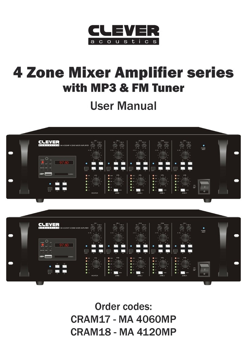
Clever Acoustics MA 4060MP User manual
Clever Acoustics
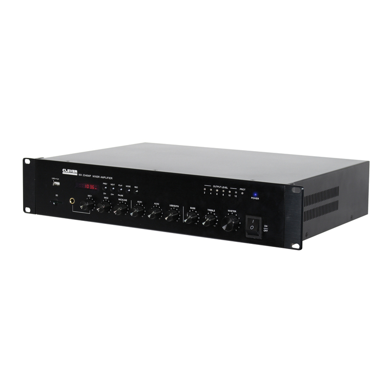
Clever Acoustics MA 260MP User manual

Clever Acoustics
Clever Acoustics CPA 40 User manual

Clever Acoustics
Clever Acoustics CRAM19A User manual
