SINO V Series User manual

V Series
Infusion Pump
User Manual
Version 1.0
Sino Medical-Device Technology Co., Ltd

Declarations:
The information contained in this manual is based on the experiences and knowledge acquired by
Sino Medical-Device Technology Co., Ltd. (Hereinafter referred to as Sinomdt) from the product
field.
Sinomdt is convinced that the information provided in this manual is accurate and reliable. But,
we could not make any guarantees for the contents of this manual. As this manual is only used to
provide the guidance for the use, operation and maintenance of infusion pump, Sinomdt shall not
assume liability for the property damages or personal injuries caused by the citations of the contents of
this manual for other purposes.
This manual copyright is owned by Sinomdt, and no reproduction or dissemination of its content
and information is allowed without the prior written permission of Sinomdt.
The contents of this manual are subject to change without notice due to product upgrades or design
improvements.
Before the installation and application of V series infusion pump, please read this manual
carefully.

Contents
1. SAFETY INFORMATION...........................................................................................1
1.1 Stipulations in the Manual ..................................................................................... 1
1.2 Safety Overview..................................................................................................... 1
1.3 Electrical / Mechanical Safety............................................................................... 2
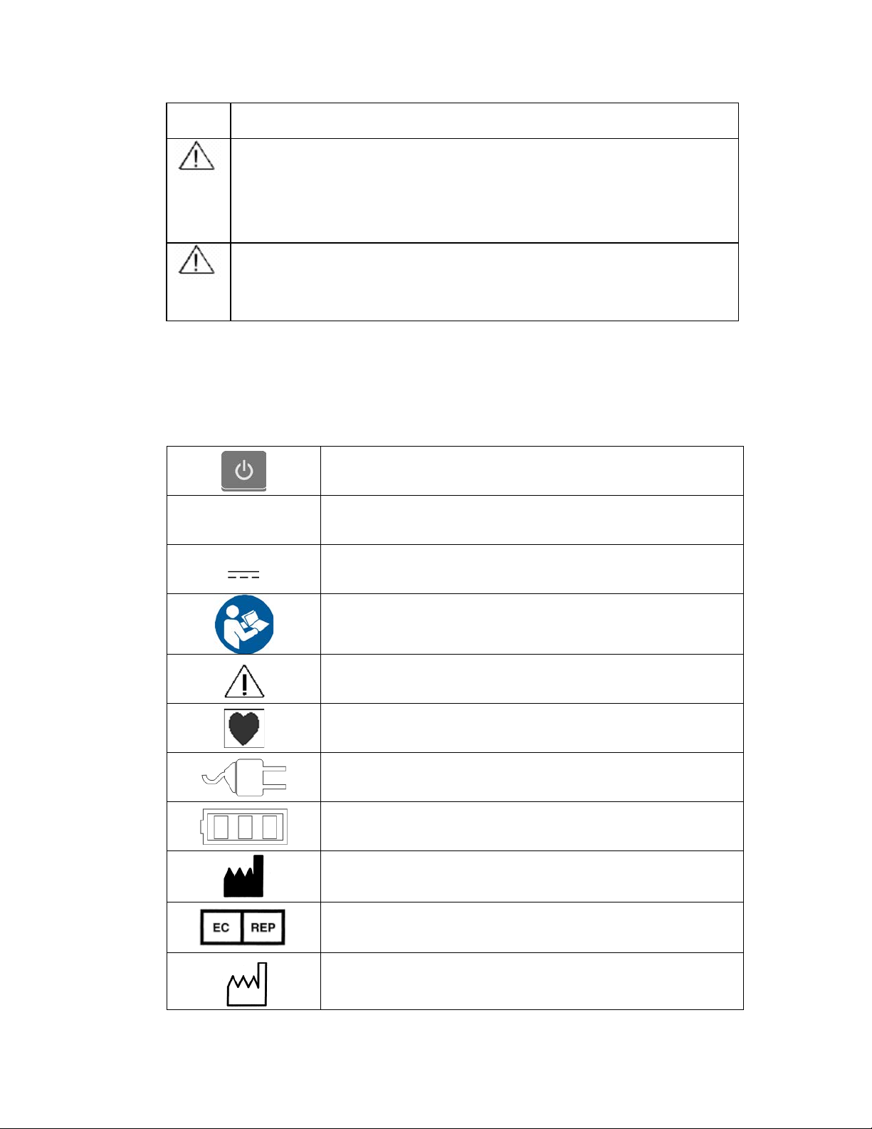
1.4 Symbols and Labels............................................................................................... 4
2. PRODUCT INTRODUCTION.....................................................................................6
2.1 Overview................................................................................................................ 6
2.2 Designations Represented by Models.................................................................... 6
2.3 Operating Principle and Range of Application...................................................... 7
2.4 Technical Characteristics and Parameters.............................................................. 7
2.6 Standard RS232 Interface .................................................................................... 12
2.7 Multi-Channel Injection....................................................................................... 12
3 . OPERATING METHODS.........................................................................................13
3.1 Pump Installation................................................................................................. 13
3.2 Power On ............................................................................................................. 14
3.3 Power On/Off and System Self-test..................................................................... 14
3.4 Installation of Infusion Components.................................................................... 15
3.5 Selection of Infusion Mode.................................................................................. 16
3.6 Infusion Parameters Setup ................................................................................... 22
3.7 Advanced Parameter Setup .................................................................................. 24
3.8 Bolus Function..................................................................................................... 28
3.9 Lighting Function................................................................................................. 28
3.10 Communication with Main Unit........................................................................ 28
3.11 Sleep Mode ........................................................................................................ 29
3.12 Keyboard Lock................................................................................................... 29
3.13 Management of the Battery Recharging ............................................................ 29
4. ALARM PRESENTATION........................................................................................30
4.1 Alarm of Non Operation ...................................................................................... 30
4.2 Alarm of Not Calibration..................................................................................... 30
4.3 Alarm of Occlusion.............................................................................................. 30

4.4 Alarm of Bubble................................................................................................... 30
4.5 Alarm of Door Open ............................................................................................ 30
4.6 Alarm of Infusion Finish...................................................................................... 31
4.7 Alarm of KVO Completion.................................................................................. 31
4.8 Alarm of Drip Sensor Abnormality...................................................................... 31
4.9 Alarm of Power Supply Breakdown.................................................................... 31
4.10 Alarm of Low Voltage Battery........................................................................... 31
4.11 Alarm of Battery Running-out ........................................................................... 31
4.12 Alarm of System Error....................................................................................... 32
4.13 Alarm Level ....................................................................................................... 32
4.14 Alarm Volume.................................................................................................... 32
5. ANALYSIS OF MALFUNCTION AND TROUBLESHOOTING.........................34
6. MAINTENANCE.........................................................................................................35
7. NATURES OF INFUSION.........................................................................................36
7.1 Natures of Rate Accuracy .................................................................................... 36
7.2 Response to Occlusion......................................................................................... 37
8.EMC............................................................................................................................39
9. STANDARD CONFIGURATION .............................................................................43
10. RELEVANT INFORMATION ................................................................................44

1
1. Safety Information
1.1 Stipulations in the Manual
The following information is applied in this manual to emphasize the hints on the messages relating
to patients or devices or the potential risks.
Caution:
Be used to remind the situation in which the device or
environmental damage may be caused.
Warning:
Be used to remind the situation in which injury or death
may be caused.
Attention:
Be used to highlight the important guiding information which
may have impact on how to use this manual and the product, or
used to provid
e some additional information, such as detailed
explanations, hints or reminders.
1.2 Safety Overview
In accordance with the equipment safety classification, V Series Infusion Pump can be classed as
Class I and Internally Powered Equipment, Type CF Applied Part, IPX4 and Continuous operation
equipment and can’t be classed to use in an Oxygen Rich Environment.
The following is an overview of safety precautions:
•Operating personnel shall not be allowed to open the outer housing of device
under any circumstances.
•It is not allowed to let the security function components of built-in device in a
failure or short circuit condition.
•If the device fails to operate normally, it is not allowed to carry out repairs on
your own. Instead, you should immediately contact with Sinomdt’s qualified
personnel authorized to repair the equipment.
•No repair parts meeting your needs are available inside the equipment.
•Comply with all the warnings and attention hints, whether it is clearly defined or
self-evident.
•Follow the stipulations specified in all safety labels on the equipment.

2
1.3 Electrical / Mechanical Safety
Only those well-trained and qualified maintenance personnel authorized by the Sinomdt can open
the outer housing of device and replace the electrical and mechanical components. Otherwise, problems
of device safety may be caused.
The V series pump complies with standard EN 60601-1 and EN60601-2-24.
The following is an overview of warning message:
1.3.1 Electrical Safety
Warning:
Risk of electric shock -
In order to protect patients and medical personnel, it is
necessary to make sure that proper grounding of equipment is arranged, and
protective grounding
of power outlets remains intact. It is prohibited to have the
triaxial cable of this device connected to twin wire socket.
Warning:
Risk of electric shock -
It is prohibited to open the outer casing of device during
the operating process or power connection. Only authorized maintenance
engineers are allowed to open it.
Caution:
Before use, the user must check and make sure that there are no obvious damages,
which may have impact on the patient safety or equipment performance. The
recommended cycle of detection is once a week or a shorter period of time. It is
recommended to replace the d
amaged parts before use if obvious damages are
found out.
Caution:
Periodic safety tests of the instrument should be conducted to ensure the safety of
device. The tests include leakage current measurement and insulation tests. The
recommended test peri
od is once a year, or the tests can be conducted in
accordance with regulatory requirements and inspection procedures.
Caution:
Prior to the cleaning, the power cord should be removed. Use soft brush or soft
cloth to wipe off the dust on the surface of device, use brush to remove the dust
on the connector or the edge of panel, or use soft cloth soaked with neutral
detergent / cold disinfectant or 70% alcohol and isopropyl alcohol to wipe off the
dust. It is not allowed to let the detergent or disinfectant permeate into the internal
part of device. Special attention should be paid to the connectors, edge of panel,
and other locations.
1.3.2Application Safety

3
Warning:
It is prohibited to operate this device beyond the limits for operating environment.
Otherwise, the device may be caused to operate abnormally.
Warning:
Not suitable for the operation under the environment in which oxygen and
nitrogen oxide flammable anesthetic are mixed. Otherwise, explosion may be
caused.
Warning:
The applic
ation of inappropriate or misaligned IV set may cause inaccurate speed
or dosage, and subsequently do harm to patients.
Warning:
We recommend to use the special IV set for pumps for injection, and
We can not guarantee the accurates for other IV sets
Warning:
In order to ensure the injection processing, suggest to use the drip clamp
Warning:
Keep attention to avoid the air into the patient when use this product
Warning:
This product is not suitable for hyperbaric oxygen chamber and MRI inspection
room.
Warning:
When using this device, attention should be paid to avoid the air admission which
may do harm to the patients.
Warning:
In order to prevent the producing of the overspeed in the infusion, the users are
suggested to connect the
drip sensor with the host well before using of this
product.
Caution:
Keep the environment clean and avoid shocks. Keep away from the aggressive
chemicals, dusts, high temperature and humidity environment.
Caution:
Electromagnetic interference - Make ensure that the installation and service
environment of this instrument are not subject to strong electromagnetic
interference, such as wireless transmitters or mobile phone interference.
Attention:
The protective cover should be arranged in place, provided that RS232 interface
of device is not in use.
Attention:
Taboo drug
(
Insulin is not suitable for infusion pump injection, since insulin

4
should be kept at a low temperature. Insulin should be injected quickly after
leaving the low temperature environment).
Attention:
The IV set should fit with the National relative sanitation and quality standard for
disposable goods; do not crossed use; after using the disposable IV set, the
operator should deal with it as the medical rubbish
Attention:
Please use the power line, battery from Sinomdt, otherwise will possibly lead to
irregular injection
1.4 Symbols and Labels
1.4.1 Safety Symbols
Standby-by
~Alternating Current
Direct Current
Refer to instruction manual/booklet
Caution
TYPE CFAPPLIED PART, the applied part is IV set
Indicator light of Mains Supply
Indicator light of battery state
Manufacturer
Authorized Representative in the European Community
Date of manufacture

5
Serial number
0123
CE marking of conformity
Company Logo
IPX4 Protected against splashing water
Non ionizing electromagnetic radiation
EEE separately collecting symbol
1.4.2 Transport Symbols
Fragile: Handle with care
Keep dry
This side up
Humidity Limitation
Atmospheric pressure limitation
Temperature limitation

6
2. Product Introduction
2.1 Overview
Microprocessor-based accuracy control motor as well as the pump tablet of drive finger-press
type peristaltic pump shall be applied in V series infusion pump to enable the medicine to be injected
into the patient body with uniform speed, accurate and safe dosage. During the clinical treatment,
Vseries infusion pump is applicable to internal medicine, surgery, pediatrics, obstetrics and gynecology,
ICU, CCU ward and other clinical infusion therapies.
Main features are listed as follows:
●A high degree of intelligence, dual-CPU chip, and real-time monitoring of the entire infusion
process ensure a more secure and reliable infusion process.
● Wide range of infusion flow rate, namely, 1ml/h~1500ml/h(for 1600V/1600VR/1800V/1800VR)
or 1ml/h~1200ml/h(for 2000V/2000VR).
● Wide range of application, and suitable for 20 drops / ml and 60 drops / ml IV set.
● High-bright LED lamp is applied to indicate the state of alarm so that the cal personnel can clearly
observe the state of infusion from a distance of 5 meters.
● Lighting lamp inside the pump. At night, it can be automatically switched on to facilitate the
operation at night of medical personnel, as long as the pump gate is opened.
● History record. The history records of more than 1500 previous infusions can be kept.
2.2 Designations Represented by Models
This series of products include the following Models:
SN-1800V (Professional, without wireless communication function)
SN-1800VR (Professional, with wireless communication function)
SN-1600V (Basic type, only support the speed mode and drip mode, no wireless
communication function)
SN-1600VR (Basic type, only support the speed mode and drip mode, no wireless
communication function)
SN-2000V (Semi-extrusion infusion pump, without wireless communication function)
SN-2000VR (Semi-extrusion infusion pump, with wireless communication function)
In addition to the wireless communication function, the specification of the 6 models is almost the
same.

7
2.3 Operating Principle and Range ofApplication
2.3.1 Operating Principle
The pump, falling into the category of volumetric type pump, is composed of finger-press type
peristaltic pump, control system, and operation display system. The finger-press type peristaltic pump
comprises motor, tape handler, peristaltic cam, wiggle cam, extrusion pump tablet, and press plate. At
the time of operation, the micro processing chip controls the rotation of motor, and drive the peristaltic
shaft to rotate after the deceleration of tape handler. The peristaltic shaft drives the peristaltic cam to
rotate, enabling extrusion pump tablets to conduct regular up and down movement under the extrusion
of cam. The extrusion pump tablets alternatively extrude the infusion tube mounted between the press
plate and extrusion tablet, and subsequently push the liquid medicine to move forward. The control
system, consisting of dual-CPU chip, motor control module and so on, is applied to accurately control
the flow rate of infusion and monitor the infusion status so that the safe and reliable infusion process can
be guaranteed in the entire process. The operation display system, consisting of LCM, control panel, etc,
is applied to realize the man-machine interaction and facilitate the operation of medical staffs.
2.3.2 Expected Purpose
V series infusion pump is adapted to the hospital department of internal medicine, surgery,
pediatrics, obstetrics and Gynecology, ICU, CCU room and other clinical infusion therapy.This product
should operated by qualified workers in hospital.
2.3.3 Expected Suitable Object
Used for the drugs injection for adult, pediatric, neonatal, etc., used in Infusion therapy.
2.3.4 Expected User
The doctor, nurse or trained qualified medical staff in the hospital.
2.3.5 Taboo
1600V/1600VR/1800V/1800VR:
Taboo drugs: insulin is not suitable for infusion pump injection.
This product is strictly prohibited for blood transfusion.
2000V/2000VR:
None.
2.4 Technical Characteristics and Parameters
2.4.1 Rate Range of Adjustment
1ml/h - 1500ml/h(for 1600V/1600VR/1800V/1800VR)
1ml/h - 1200ml/h(for 2000V/2000VR)
When the speed is at 1-99.9 ml/h, the flow rate of infusion increases by 0.1 ml; When the speed is
above 100 ml/h, the flow rate of infusion increases by 1 ml/h.

8
Measuring equipment calibration unit: ml/h
2.4.2Accuracy
Flow rate accuracy: less than ± 5%
2.4.3 Purge Rate
200ml/h~1000ml/h,Adjustable
2.4.4 Delivery Search
0.1ml ~ 9999ml,
Below 100ml, the accuracy is 0.1ml. Above 100ml, the accuracy is 1ml
2.4.5 Delivery Limit
0.1ml~9999ml, Adjust step 0.1ml. Above 100ml,the step is 1ml
2.4.6 Occlusion Alarm Level
Infusion pump obstruction pressure's setting range is 100mmHg~900mmHg(13.3kPa~120kPa),
Adjustable ten level, error is ± 50mmHg or ± 25% (6.6kpa), the bigger should be taken.
2.4.7 Bubble Detector
Ultrasonic detection method, bubble above 25ul can detected.
2.4.8 KVO Rate
0.5~5ml/h, Adjustable, the default value is 2ml/h
2.4.9 History Record
This series products can store more than 1500 historical records.
Automatic record key operations and event information after system booting , including infusion start
time, accumulation, flow rate, state,etc..
2.4.10Alarm
In order to ensure the safety of infusion, this series products with the following warning or
reminding function:
over time, not calibration, occlusion, bubble, door open, finish, KVO completion, drip sensor
abnormality, power supply breakdown, under voltage battery, battery running-out, system error.
Detailed information see "Alarm Presentation"
2.4.11 Power
Power supply voltage: A.C. 100V - 240V D.C. 12V
Power frequency: 50/60Hz
Battery voltage: DC 12V
Battery working time: under full charge condition, Equipment can work more than 8 hours with a speed
of 25ml/h
Maximum power: 28VA

9
2.4.12 Environment
Working environment:
Temperature: 5 ~40 ℃
Humidity: 20% ~90%
Atmospheric pressure: 86kpa~106kpa
Transportation and storage condition:
Temperature: -20~+55℃
Humidity: ≤ 95%
2.4.13 Dimension
129mm×130mm×215mm
2.4.14 Net Weight
1.8kg
2.4.15 Supported Brand
The infusion pump can record 12 different manufacturers' IV sets, 10 drops/ml,15 drops/ml , 18
drops/ml, 20 drops/ml and 60 drops/ml included. the 12 manufacturers were: U_1、U_2、U_3、U_4、
U_5、U_6、U_7、U_8、U_9、U_10、U_11、U_12,"U_XX" number of IV set should pass the calibration
function, then the corresponding IV set can be use.
Warning:
If the IV set without calibration, it may lead to inaccurate infusion.
User choose IV set should get CE certificate, or get the allow for accessing
into local medical equipment market.
2.5 ExternalAppearance & Structure
The main unit of infusion pump mainly consists of the outer casing, pump gate, operating panel,
peristaltic pump, and drip sensor. Its external appearance and structure is shown in below Figure:

10
The specific descriptions of all parts are listed as follows:
1.System errorAlarm Indicator -- used for alarm indication when system error occurred
2.AC Indicator -- the indicator lights up when connected to AC power,
3.Power key -- long press to turn on/off
4./5 Drip mode indicator /Speed mode indicator -- drop mode is different with other modes in digital
display unit, it display lamp for displaying the current infusion data unit
6. LED Display—to show the speed data.
7.LCD Display -- to show the related data, status, alarm information, etc..
8.Numeric Keypad -- for inputting numerical information, Number 3 and number 6 owns choosing
upper or lower function. When you entered 3 or 6, except in the situation for choosing upper or lower,
other situation only entered number 3 or number 6.
9.MENU Button/Return Button –Select the menu program and return .
10.Confirm Button/Select Button---Select the program and enter it; Shift the parameters on the some
interface to select the parameters.
11.Purge Button--Press the key and press it again for 5 seconds, Start the purge function. Release the
key to enable to stop it.
12.Silence Button/Clear Button--To be used for buzzer on-silence after alarm; Enter the parameters,
Reset the infusion amount.
13.Start Button/Pause Button--To be used for start or pause the infusion.
14.Tubing clamp —Clamp the pipeline after the pump gate is opened to avoid the excessive output of

11
liquid medicine.
15.Jacklight— To be used for nighttime illumination.
16.Occlusion Sensor—Detect the pressure in infusion tube line.
17.Pump Fingers—Extrude the pipeline, enabling the liquid to be drained from the infusion
components.
18.Pump Door—Fix the infusion tube line components to be mounted.
19.Door Handle—To be used for the opening and closing of pump gate,
20.Pressure Plate—Use constant pressure to hold down the pipeline of infusion components.
21.Bubble Sensor—Detect the air bubble in infusion tube line.
22.Drip Sensor---Detect the drip.
23.Infusion State Indicator/Alarm Indicator--The difference status, For examples, the infusion status,
alarm status and so on, the indicator light can show different status and the indicator color
The name of all parts for infusion pump behind:
1. USB(interface)is used for the connection of other device.(Reserved Interface)。
2. Drip sensor is used to detect the status of liquid drip inside the Murphy's dropper of IV set, and count

12
the liquid drips splashed into the Murphy's dropper.
3. The fixation clamp is used for fixing infusion pump onto the infusion stand or bedstead.
4. Fixation handle--Rotating and adjusting the fixation which it is lock or release
5. Power supply interface is used for the connection ofAC power supply.
6. DC 15V power output interface is used for output DC15V power supply.
7. RS232 interface is used for external communications.
8. DC12V Power input interface is used for the connection of 12v external DC power supply.
9. Calling nurse interface is used for the connection of nurse-calling system.
2.6 Standard RS232 Interface
The pump has a standard RS232 interface and it is communicated each other. RS232 connected
line is asked to use shielded wire an it should be accord with the standard request of information
technique and safe standard for IEC60950-1. For more detailed information, Please ask our company to
the RS232 interface agreement. The device must be connected with the specified equipment.
2.7 Multi-Channel Injection
It is recommended that the infusion device use a one-way valve under using multi-channel
injection. If there is no one-way value in the infusion tube, and it happened to be able to detect the block
for the patient and it can lead to the drug corner. After release the block, the drug corner will inject the
patient with unknown speed. It is very dangerous to the patient.

13
3 . Operating Methods
The operating process of pump is listed as follows:
3.1 Pump Installation
● By rotating the fixation clamp at the back of device, it is possible to enable the
device to be fixed onto the infusion stand .
●When pump is fixed onto the vertical strut, at first fixation clamp fixed onto the strut , clamp the
strut , and then rotating the fixation clamp and clamp the strut, it will fixed onto the vertical strut.

14
3.2 Power On
After the external power supply is switched on, the external power indicator is on, the pump is at
the power-on state. If the pump can't open and the current battery power is not enough , the pump will
charge automatically.
3.3 Power On/Off and System Self-test
After the external power supply is switched on, the external power indicator is on, the

15
pump is at the power-on state. At this moment, press the key for 1 second to enable the start-up
of device. Under the premise that the internal battery is used, the battery indicates the current battery
power after the power switch is pressed to enable the start-up of device.
The system starts to conduct self-test after the start-up of device. At this moment, the buzzing
sound will be given out, the indicator and alarm light will bright up according to priority, and the pump
will automatically check each of the functions (Note: All keys will be tested during the self-test process.
In order to avoid an alarm for key error, please do not press any key). If there is no error message on
the main interface of LCD screen after the self-test, that means the pump works normally. At the
moment, the device is in standby state, The pump will give out alarm if the system is in abnormal
condition. For this regard, please refer to the description of alarm.
After the external power supply is switched on, Press the key for seconds to enable switch off
device. Under infusion status, Press to stop infusion, Press the key for seconds to
enable switched off device. After power off, the data stored in the memory chip is not lost due to power
off.
3.4 Installation of Infusion Components
Make the infusion components ready. Hang the IV bottle (or bag) onto the IV stand (Note: the
infusion bottle or bag should be placed 20cm ~ 80cm higher than the patient’s heart), open the package
of IV set components, and close the roller clamp of IV set. After the infusion components are properly
connected, use your hands to extrude the Murphy's dropper of IV set, and enable it to be filled with
liquid (An appropriate filling amount is one third of the Murphy's dropper). Open the roller clamp, fill
the infusion tube with infusion liquid to exhaust the air bubble, and then close the roller clamp.
Properly install the infusion tube. Lift up the pump handle, open the door, start the installation
from up to down, smoothly insert the tube into the pipe clamp, bubble sensor, and tubing clamp
according to priority . After the pipeline installation is finalized, it is possible to lift up the door handle,
ensure that the pulling hook of door handle has fastened the door locking pin, successively press down
the latch handle and close the pump door. At this moment, the surface of door handle should be in
parallel with the pump.
If you select the “drip mode” or enable the “drip sensor alarm function” , the drip sensor
should be installed. Have the drip sensor installed between the top of Murphy's dropper nozzle and
liquid level and try to keep the Murphy's dropper in the vertical position so that the drip sensor can
accurately detect the status of the liquid drip inside the Murphy's dropper (see Figure ).

16
Figure: Schematic Diagram for Installation of Drip Sensor
Under using, as the step above, clean up the air which the infusion set is full and install it onto the
infusion pump.
Warning: Before the infusion install, the user must clean up the air in the
infusion to avoid the air admission.
Warning:
the infusion bottle or bag should be placed 20cm ~ 80cm higher
than the patient’s heart
Caution:
The infusion tube must near Pump Fingers.
● After close pump door, Press "Bolus Button" to clean up the air in the infusion tube.
Release the hands upon the medical liquid flow out.
● When all the parameter is setting completely, inserted the needle into the patient's vein.
Press "Start" Button" again to enable start the infusion.
Warning:
Before using the device, The user must clean up the air in the infusion tube
to avoid the air admission which may do harm to the patients.
3.5 Selection of Infusion Mode
There are totally five optional modes for infusion with the pump, which are “Speed Mode” ,
“Drip Mode” , “Body Weight Mode” , “Time Mode” and “Infusion Plan”
In the state of pause, press to enter the “setup interface” as shown in Figure:
This manual suits for next models
1
Table of contents
Popular Water Pump manuals by other brands

BGS GENERAL
BGS GENERAL PBO Operating manual and Spare parts list

Edbro
Edbro PTO 01-01 General installation guide

Dover
Dover PSG ALL-FLO F200 Series Installation operation & maintenance

Xtreme Power
Xtreme Power 75132 Owner's manual and safety instructions

Roller
Roller E-Control operating instructions

Tower Hobbies
Tower Hobbies BRZPUMP Installation and operation manual