Sitex ES502 User manual

User Manual
Copyright 2008 Seiwa - Hong Kong
All rights reserved. Printed in Italy. No part of this publication may be reproduced or distributed in any form or by any
means, or stored in a database or retrieval system, without prior written permission of the publisher.
ES502
Dual Frequency 50 & 200kHz Black Box Fish Finder
code: (D 110608e)

4User Manual
Important Information
CAUTION
♦Please read through this manual before the first operation. If you have any
questions, please contact the Company's customer service or your local
dealer.
♦The ES502 is not built water proof. Please make sure to avoid water intru-
sion into the unit. Water damage is not covered by the warranty.
♦Extensive exposure to heat may result in damage to the ES502.
♦Connection to the power source with reversed polarity will damage the ES502
severely. This damage is not covered by the warranty.
♦The ES502 contains dangerous high voltage circuits which only experienced
technicians MUST handle.
WARNING
♦When plugging in or unplugging a transducer to the ES502 make sure power
is turned off.
NOTE We will not be liable for errors contained herein, or for incidental or
consequential damages in connection with the performance or use of this
material.

5
User Manual
Contents
Important Information ................................................................................. 4
CAUTION ................................................................................. 4
WARNING ................................................................................. 4
About this User Manual ................................................................................. 7
INTRODUCTION ................................................................................. 7
CONVENTIONS USED ................................................................................. 7
HOW THIS USER MANUAL IS ORGANIZED ............................................................... 8
IF YOU NEED ASSISTANCE ................................................................................. 8
1. Overview ................................................................................. 9
1.1 FISH FINDER ................................................................................. 9
Features & Functions ................................................................................. 9
1.2 Selecting the Fish Finder port ........................................................................ 10
2. Fish Finder ............................................................................... 11
2.1 UNDERSTANDING THE FISH FINDER PAGE ..................................................... 11
2.1.1 Understanding the Echogram display ................................................... 12
2.2 DISPLAYING THE FISH FINDER PAGE ............................................................. 13
2.2.1 How to select the Fish Finder page ....................................................... 13
2.2.1.1 Selection by Soft Key ............................................................ 14
2.2.2 Fish Finder Full page .......................................................................... 15
2.2.3 Dual Frequency page ......................................................................... 16
2.2.4 Zoom page 17
2.2.5 Chart/Fish page 17
2.2.6 Fish Finder and Radar pages ONLY FOR COLOR MAX 11/COLOR MAX PRO/
COLOR MAX WIDE E/COLOR MAX WIDE I/COLOR MAX SEALINK I/
COLOR MAX SEALINK E/EXPLORER II PLUS/COLOR MAX 15/TRAWL PLOT 12/
TRAWL PLOT 12 SD ........................................................................... 18
2.3 ZOOM MODES ............................................................................... 19
2.3.1 The Bottom Lock Zoom ...................................................................... 19
2.3.2 The Marker Zoom .............................................................................. 19
2.4 SOUNDER ADJUSTMENTS WITH SOFT KEYS .................................................... 19
2.5 INFO ON FISH FINDER: SYSTEM INFORMATION ............................................... 20
2.5.1 The System Update menu .................................................................. 20
3. Setup your Fish Finder ............................................................................... 21
3.1 FISH FINDER SETUP MENU ........................................................................... 21
3.1.1 Preset Mode ............................................................................... 21
3.1.2 Gain Mode ............................................................................... 21
3.1.3 Range Mode ............................................................................... 21
3.1.4 Depth ............................................................................... 21
3.1.5 Shift ............................................................................... 22
3.1.6 Bottom Range ............................................................................... 22
3.1.7 Frequency ............................................................................... 22
3.1.8 Interference Rejection ....................................................................... 22
3.1.9 Sensitivity ............................................................................... 22
3.1.9.1 Frequency ........................................................................... 22
3.1.9.2 Gain ............................................................................... 22
3.1.9.3 STC ............................................................................... 22
3.1.9.4 STC Length .......................................................................... 22
3.1.9.5 STC Strengh ........................................................................ 23
3.1.9.6 Surface Noise Filter ............................................................... 23

6User Manual
3.1.10 Display Setup ............................................................................... 23
3.1.10.1 Color Settings ONLY FOR COLOR CHART PLOTTER ................................ 23
3.1.10.2 Scrolling Speed .................................................................... 23
3.1.10.3 White Line ........................................................................... 23
3.1.10.4 Fish Symbols ........................................................................ 23
3.1.10.5 Water Temperature ............................................................... 23
3.1.11 Transducer Setup .............................................................................. 24
3.1.11.1 Keel Offset ........................................................................... 24
3.1.11.2 Calibrate Sound Speed .......................................................... 24
3.1.11.3 Calibrate Water Speed ........................................................... 24
3.1.11.4 Calibrate Water Temperature .................................................. 24
3.1.11.5 Calibrate Aux Temperature ..................................................... 24
3.1.12 Alarms ............................................................................... 24
3.1.12.1 Shallow Water ...................................................................... 24
3.1.12.2 Depth Water ........................................................................ 25
3.1.12.3 Temperature Upper ............................................................... 25
3.1.12.4 Temperature Lower ............................................................... 25
3.1.12.5 Temperature Rate ................................................................. 25
3.1.12.6 Fish Alarm ........................................................................... 25
3.1.13 Load Settings from User C-CARD ......................................................... 25
3.1.14 Save Settings to User C-CARD ............................................................ 25
3.1.15 Restore Current Preset Defaults .......................................................... 25
4. ES502 ............................................................................... 27
4.1 TECHNICAL SPECIFICATIONS ....................................................................... 27
4.2 DIMENSIONS ............................................................................... 28
4.3 MOUNTING THE FISH FINDER ....................................................................... 28
4.3.1 Installation ............................................................................... 28
4.3.2 Installing Optional Devices ................................................................. 29
4.4 STATUS LED ............................................................................... 29
4.5 EXTERNAL CONNECTIONS ............................................................................ 30
4.6 POWER SUPPLY WIRING DIAGRAM ................................................................ 31
4.7 SUGGESTED PLOTTER CONNECTIONS ............................................................ 32
5. Transducers ............................................................................... 33
6. Frequently Asked Questions ............................................................................ 35
Analytical Index ............................................................................... 39
CERTIFICATE OF LIMITED WARRANTY .................................................................. 41

7
User Manual
About this User Manual
INTRODUCTION
The chart plotter combined with the sonar performance of the Fish Finder is one
of the most advanced marine navigation system available.
Please read carefully this User Manual to learn the operating features for your
unit. Refer to your chart plotter User Manual for all other unit operating instruc-
tions.
CONVENTIONS USED
Throughout this User Manual, the labelled keys are shown in capital letters en-
closed in square brackets, for example [ENTER]; the software keys are shown in
small capital letters enclosed in square brackets, for example [EDIT].
Menu operations are in bold characters listed by keys sequence with the menu
names enclosed between inverted commas, for example [MENU] + "ALARMS"
+ [ENTER] means: press the [MENU] key, using the cursor key select the Alarms
menu and then press [ENTER].
Any menu operation and functions activation in this User Manual is related to the
following chart plotter models (see the following table). Whenever it is necessary,
a note has been inserted for those models with operational differences.
CHART PLOTTER NAME DESCRIPTION SOFTWARE
COLOR MAX 5E 5" Sunlight Readable Vertical Color Display S4egSW5vc
External Smart GPS Receiver
COLOR MAX 5I 5" Sunlight Readable Vertical Color Display S4igSW5vc
Internal GPS Receiver
COLOR MAX 6 5.6" Sunlight Readable Color Display S3egSW7c
External GPS Receiver
NAVMATE E 5.6" Sunlight Readable Vertical Color Display S3egSW7vc
External Smart GPS Receiver
NAVMATE I 5.6" Sunlight Readable Vertical Color Display S3igSW7vc
Internal GPS Receiver
COLOR MAX WIDE E 7" Sunlight Readable Wide Color Display S4egSW7wc
External Smart GPS Receiver
COLOR MAX WIDE I 7" Sunlight Readable Wide Color Display S4igSW7wc
Internal GPS Receiver
COLOR MAX WIDE E 7" Sunlight Readable Wide Color Display S3egSW7wc
External Smart GPS Receiver
COLOR MAX WIDE I 7" Sunlight Readable Wide Color Display S3igSW7wc
Internal GPS Receiver
COLOR MAX SEALINK E 7" Sunlight Readable WVGA Color Display S4egSW8wc
External Smart GPS Receiver

8User Manual
COLOR MAX SEALINK I 7" Sunlight Readable WVGA Color Display S4igSW8wc
Internal GPS Receiver
COLOR MAX PRO 11" Sunlight Readable Color Display S4egSW11c
External Smart GPS Receiver & Video Input
COLOR MAX 11 11" Color Display S3egSW11c
External Smart GPS Receiver & Video Input
COLOR MAX 11* 11" Color Display XSegSW11c
External Smart GPS Receiver & Video Input
TRAWL PLOT 12 SD 12" Color Display S5egSW12c
External Smart GPS Receiver & Video Input
TRAWL PLOT 12* 12" Color Display XSegSW12c
External Smart GPS Receiver & Video Input
COLOR MAX 15 15" Color Display S5egSW15c
External Smart GPS Receiver & Video Input
COLOR MAX 15 15" Color Display S3egSW15c
External Smart GPS Receiver & Video Input
EXPLORER II Plus Controller for Color Display S5egSWctc
External Smart GPS Receiver
EXPLORER II Plus Controller for Color Display S3egSWctc/ctcj
External Smart GPS Receiver
EXPLORER II Plus* Controller for Color Display XSegSWctcj
External Smart GPS Receiver
NOTE* To connect the unit below s/n 4129999 (before February 2005) please contact
your local dealer (to make the hardware change necessary).
HOW THIS USER MANUAL IS ORGANIZED
♦CHAPTER 1: Overview
Introduction to the basic information on the Fish Finder, its features
and use.
♦CHAPTER 2: Fish Finder
Helps you understand how the chart plotter is connected to the Fish
Finder and how to operate to improve your fishing.
♦♦
♦♦
♦CHAPTER 3: Setup your Fish Finder
Description of the Fish Finder Setup menu.
♦♦
♦♦
♦CHAPTER 4: ES502
Technical specification, dimension and installation of the ES502 and
set up of the hardware configuration.
♦♦
♦♦
♦CHAPTER 5: Transducers
Introduction to the basic information on the transducer (device that
transmits and receives sound waves into the water).
♦♦
♦♦
♦CHAPTER 6: Frequently Asked Questions
The Analytical Index is at the end of this User Manual.
IF YOU NEED ASSISTANCE
If your chart plotter does not operate properly, please refer to the chart plotter
User Manual.

9
User Manual
1. Overview
The Fish Finder consists of a high power transmitter, sensitive receiver and a
transducer. The Fish Finder sends an electrical pulse to the transducer which
contains an element that converts the pulse into acoustic (sound) wave which is
sent through the water. As this wave travels from the transducer to the bottom, it
may strike fish, structures, thermoclines (temperature changes in the water).
When the wave strikes an object(s) a certain amount of the wave is reflected back
to the transducer depending on the composition and shape of the object. When
the reflected wave is returned to the transducer it is converted into a voltage and
is amplified by the receiver, processed and sent to the display. The speed of sound
in water is roughly 4800 ft./sec, so the time lapse between the transmitted signal
and the received echo can be measured and the distance to the object deter-
mined.
Fig. 1 - Fish Finder working principle
1.1 FISH FINDER
Features & Functions
♦A-Scope (displays Sonar Echo in real time)
♦2X and 4X Zoom (capability to magnify any part of the Echogram image
of a fixed rate)
♦Full auto to manual, working preset modes (Fish, Cruise)
♦Bottom Lock (capability to magnify a user defined range around the
bottom)
♦White Line (help distinguish between fish and bottom, when fish are
swimming close to the bottom)
♦STC (allows reducing or eliminating the surface clutter)
♦Interference Rejection (allows reducing interference from other boats/
Fish Finders)

10 User Manual
♦Noise Filter
♦Fish Symbol feature (*)
♦Automatic Setup Transducer. Recognition for devices (automatic
transducer identification and parameters setup for best performance)
♦Alarms Handling (Shallow Alarm, Depth Water Alarm, Fish Alarm, Tem-
perature Upper, Temperature Lower)
NOTE* On specific software version available.
1.2 SELECTING THE FISH FINDER PORT
If the Fish Finder is connected to the Port 2 (see Par. 4.7), follow the procedure:
[MENU] + [MENU] + "ADVANCED" + [ENTER] + "Input/Output" + [ENTER]
+ "Port 2 Input" + [ENTER] + "BBFF 50/200" + [ENTER]

11
User Manual
2. Fish Finder
This chapter is intended to help you understand how the chart plotter with the
Fish Finder connected operates to improve your fishing.
2.1 UNDERSTANDING THE FISH FINDER PAGE
The display on chart plotters shows a history of time of the echoes received by
the transducer. The chart plotters have a menu that allows adjustments to re-
ceiver sensitivity, depth range and scrolling speed of the Fish Finder display.
Color Bar
5
3
Echogram window
Depth ruler
2
Variable Depth Marker (VDM)
Zoom Bar
8
9
7
4
Digital Depth
Water temperature
Warning message
1
7
1
5
3
6
8
9
A-Scope
10
6
2
6
Alarm Bar
11
4
10
Operating Frequency
11
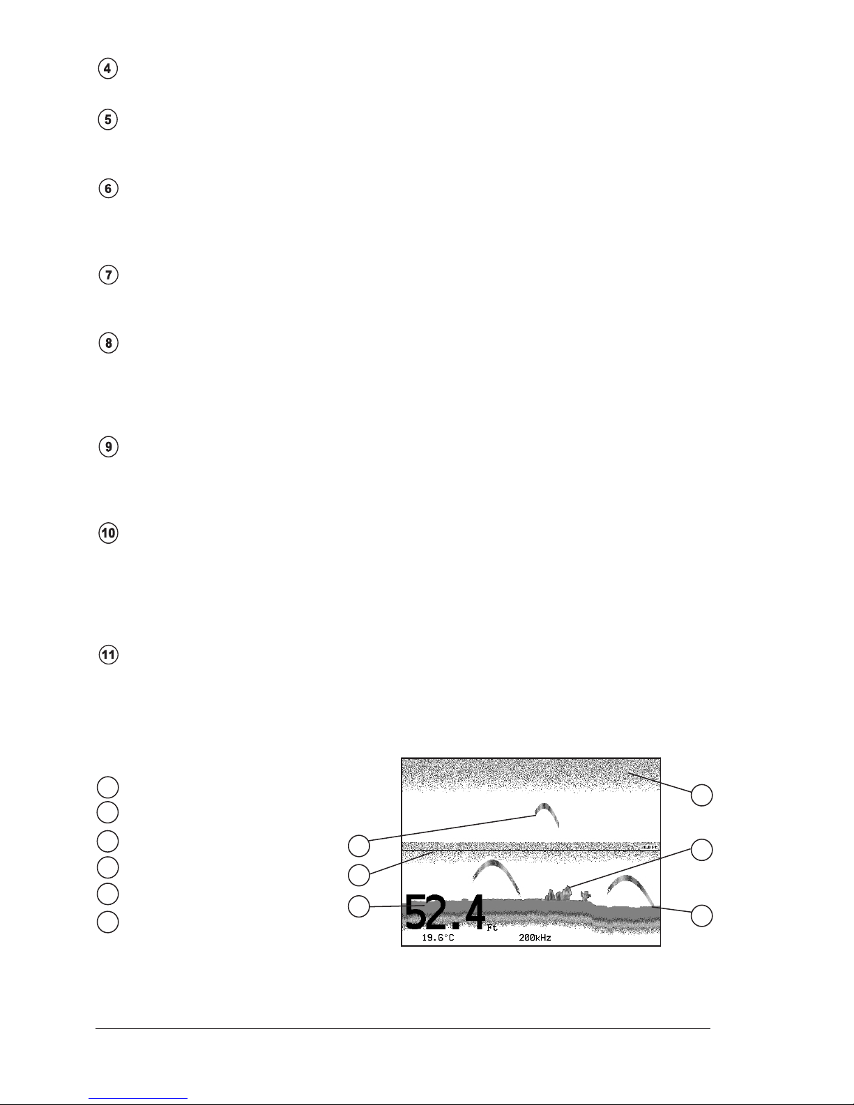
Fig. 2.1 - The Fish Finder page
The following is a short description of terms listed in the previous Fig. 2.1:
Warning Message
Flashing label "Simulation" when the echo sounder is in Simulation mode.
Echogram window
Graphic presentation of sonar soundings recorded as a continuous profile
scrolling across the screen from right to left. Such recordings represent the
image of the water beneath your boat, items appear as they pass under your
transducer; the items on the right side of the screen are closer to you than
those on the left. The correct interpretation of the Echogram allows retrieving
useful information about what is under the boat. See the following Par. 2.1.1
for more information.
Color Bar
Colored scale located on the left side of the screen that shows the colors used
in the Echogram to represent the echoes strength. The color on the top of the
bar represents the maximum sonar strength, while the color on the bottom of
the bar represents the minimum sonar strength.
12 User Manual
Digital Depth
Readout of the current bottom depth.
Water Temperature
Readout of the current water temperature returned by the TEMP 1 sensor
included into specific transducers.
Alarm Bar
Bar located on the right side of the Depth Ruler, showing the shallow water
and deep water alarm values. The alarm is triggered when depth is outside
the range.
Depth Ruler
Vertical graduated bar located along the right side of the screen. It is a scale
which reflects the depth of the area being displayed.
Variable Depth Marker (VDM)
Horizontal line on to the Echogram window with a depth label. The up/down
cursor keys can move it up and down. The label displays the depth of the
cursor position. It can be moved to any location pinpointing the depth of a
target.
Zoom Bar
Bar located on the left side of the Depth Ruler, showing the portion of the
Echogram currently represented in the zoomed window (on the left part of
the screen). It is turned On selecting the Echo Sounder Split page.
A-Scope
A real time representation of fish and bottom features passing through the
beam of the transducer. It is drawn as horizontal lines whose length and hue
is proportional to the sonar strength returned. When the default palette is
selected, the strongest sonar returns will be shown as the color displayed of
the top of Color Bar while the weakest as the bottom color.
Operating Frequency
Readout of the selected operating frequency.
2.1.1 Understanding the Echogram display
The main elements that can be easily distinguished into an Echogram are:
White Line
5
3
Thermoclines
2
4
Surface Clutter
Structures
Fishes
1
6
Bottom Echo Profile
1
4
3
2
6
5
Fig. 2.1.1 - The Fish Finder Echogram

13
User Manual
Fishes
Fishes are represented as arcs because of the cone angle of the transducer.
In fact as the boat passes over the fish the leading edge of the cone strikes
the fish, causing a display pixel to be turned on. As the boat passes over the
fish, the distance to the fish decreases turning each pixel on at a shallower
depth on the display. When the boat is directly over the fish, the first half of
the arch is formed and since the fish is closer to the boat, the signal is stron-
ger and the arch is thicker. As the boat moves away from the fish, the dis-
tance increases and the pixels appear at progressively deeper depths forming
the remaining half of the arch.
Thermoclines
Are the zones where two layers of different water temperatures meet. The
greater the temperature differential, the thicker the thermocline is shown on
the screen. Thermoclines are represented as horizontal stripes of noise. They
are very important for fishing since often many species of game fish like to
suspend in, just above, or just below the thermoclines.
White Line
The White Line shows the difference between hard, soft bottoms and even
distinguishes between fishes and structures located near the bottom. In this
way it is easier to tell the difference between a hard and soft bottom and even
to distinguish fishes and structures located nearby the bottom. For example,
a soft, muddy or weedy bottom returns a weaker echo that is shown with a
narrow white line while a hard bottom returns a strong echo that causes a
wide white bottom line.
Surface Clutter
Appears like noise at the top of the screen extending many feet below the
surface. It’s caused by many things, including air bubbles, bait fish, plankton
and algae.
Structures
Generally, the term “structure” is used to identify objects like wrecks and
weeds rising from the bottom.
Bottom Echo Profile
Bottom profile recorded by the Fish Finder. When the echo sounder is set in
auto-range mode it is automatically kept in the lower half of the screen.
Other Elements
Large anchoring cables are returned by the echo sounder as very long and narrow
arcs on the screen.
2.2 DISPLAYING THE FISH FINDER PAGE
This section will take you through the frequently used operations and assist you
to customize the look of the chart plotter using the Fish Finder.
NOTE The Fish Finder display page is available only if the Fish Finder is connected
and powered On.
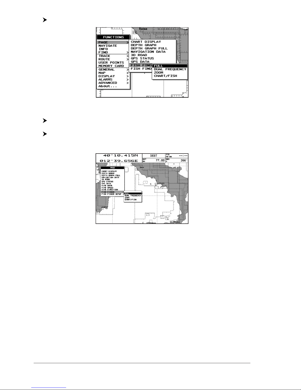
2.2.1 How to select the Fish Finder page
The Page Selection menu allows you to change the Fish Finder page displayed. To
access this menu:
14 User Manual
[MENU] + "PAGE" + [ENTER] + "FISH FINDER" + [ENTER]
Fig. 2.2.1 - Fish Finder page selection by Menu
COLOR MAX 11/COLOR MAX PRO/COLOR MAX 15:
[DATA] + "FISH FINDER" + [ENTER] + select the desired page + [ENTER]
TRAWL PLOT 12/TRAWL PLOT 12 SD:
[PAGE] + "FISH FINDER" + [ENTER] + select the desired page + [ENTER]
The screen is shown in the following figure:
Fig. 2.2.1a - Fish Finder page selection by Menu
The menu now shows four selections related to the Fish Finder, Full, Dual Fre-
quency,Zoom and Chart/Fish. Move the cursor to select the desired item and
then press [ENTER].
NOTE When the Radar* is connected, two other displaying pages are available too,
Radar/FF and Radar/FF/Chart/Nav Data. See the Radar* User Manual
for more information.
(*) ONLY FOR COLOR MAX 11/COLOR MAX PRO/COLOR MAX WIDE E/COLOR MAX WIDE I/COLOR MAX
SEALINK E/COLOR MAX SEALINK I/EXPLORER II PLUS/COLOR MAX 15/TRAWL PLOT 12/TRAWL
PLOT 12 SD
2.2.1.1 Selection by Soft Key
The default soft keys configuration can be customized. When the Fish Finder is con-
nected, any soft key can be assigned any of the Fish Finder pages.
Pressing and holding down any of the four soft key shows a pop-up window on the
top of the soft key pressed that contains all possible data pages assignable to the soft
key pressed. Move the cursor key up/down to place the selector on the desired item;
move the cursor key to the right or press [ENTER] to set the selected item; move
the cursor key to the left or press [CLEAR] to close the pop-up window.
15
User Manual
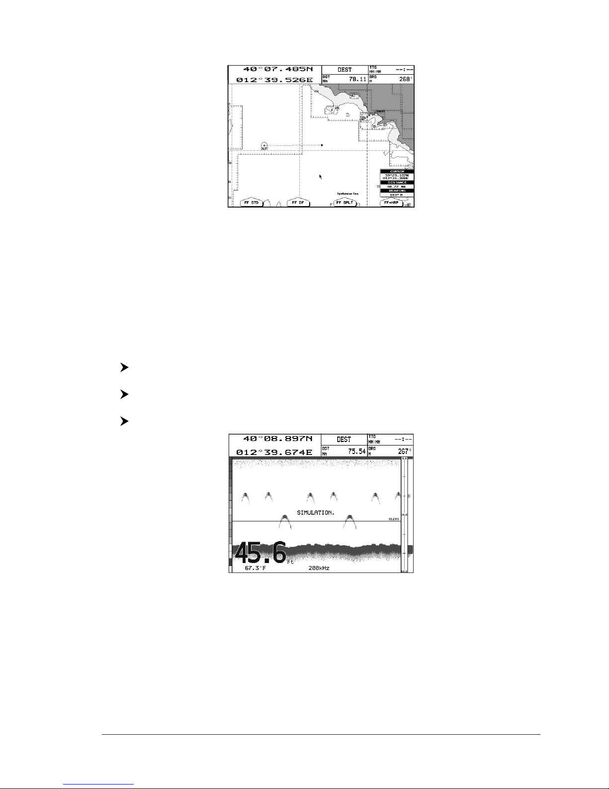
In the picture below, the four soft keys are customized to select the four Fish
Finder page:
Fig. 2.2.1.1 - Fish Finder page selection by Soft Key
Press [FF STD] to show the Full page, [FF DF] to show the Dual Frequency page,
[FF SPLT] to show the Zoom page and [FF +MAP] to show the Chart/Fish page.
NOTE When the Radar* is connected, any soft key can be assigned any of the Fish
Finder or Radar* pages. See the Radar* User Manual for more information.
(*) ONLY FOR COLOR MAX 11/COLOR MAX PRO/COLOR MAX WIDE E/COLOR MAX WIDE I/COLOR MAX
SEALINK E/COLOR MAX SEALINK I/EXPLORER II PLUS/COLOR MAX 15/TRAWL PLOT 12/TRAWL
PLOT 12 SD
2.2.2 Fish Finder Full page
To display the Fish Finder Full Page Echogram, follow this procedure:
[MENU] + "PAGE" + [ENTER] + "FISH FINDER" + [ENTER] + "Full" + [ENTER]
COLOR MAX 11/COLOR MAX PRO/COLOR MAX 15:
[DATA] + "FISH FINDER" + [ENTER] + "Full" + [ENTER]
TRAWL PLOT 12/TRAWL PLOT 12 SD:
[PAGE] + "FISH FINDER" + [ENTER] + "Full" + [ENTER]
Fig. 2.2.2 - The 200kHz Fish Finder Full page
NOTE The frequency displayed depends on the selection done in the Frequency item
(see Par 3.1.9).
The MENU key
Pressing [MENU] activates the Fish Finder Setup menu (see Par. 3.1). Pressing
[MENU] subsequent times toggles between the Fish Finder Setup menu and the
Main menu.
The Cursor key
Moving the Cursor key up/down adjusts the Variable Depth Marker (VDM) up or
down on the screen.
16 User Manual
The ENTER key
Pressing [ENTER] activates the Sensitivity menu (see Par. 3.1.1) that allows
tuning the Gain, the Surface Noise Filter and the STC.
Fig. 2.2.2a - Sensitivity sub-menu
Pressing [CLEAR] turns off the Sensitivity menu.
The CLEAR key
By pressing [CLEAR] the Variable Depth Marker (VDM) is hidden.
The ZOOM IN and ZOOM OUT keys
From this page pressing [ZOOM IN] once changes to Zoom 2X, pressing
[ZOOM IN] twice changes to Zoom 4X, while pressing [ZOOM OUT] reverts to
Zoom 2X and no zoom.
2.2.3 Dual Frequency page
To display the Fish Finder Dual Echogram, follow this procedure:
[MENU] + "PAGE" + [ENTER] + "FISH FINDER" + [ENTER] + "Dual Fre-
quency" + [ENTER]
COLOR MAX 11/COLOR MAX PRO/COLOR MAX 15:
[DATA] + "FISH FINDER" + [ENTER] + "Dual Frequency" + [ENTER]
TRAWL PLOT 12/TRAWL PLOT 12 SD:
[PAGE] + "FISH FINDER" + [ENTER] + "Dual Frequency" + [ENTER]
Fig. 2.2.3 - Fish Finder Dual Frequency mode
The Cursor key
Moving the cursor to the right or the left moves the Variable Depth Marker (VDM)
between the 50 and 200kHz displays. Moving the cursor up or down will move the
VDM up and down. Press [CLEAR] to hide the VDM.
The ZOOM IN and ZOOM OUT keys
From this page pressing [ZOOM IN] once changes to Zoom 2X, pressing
[ZOOM IN] twice changes to Zoom 4X, while pressing [ZOOM OUT] reverts to
Zoom 2X and no zoom.

17
User Manual
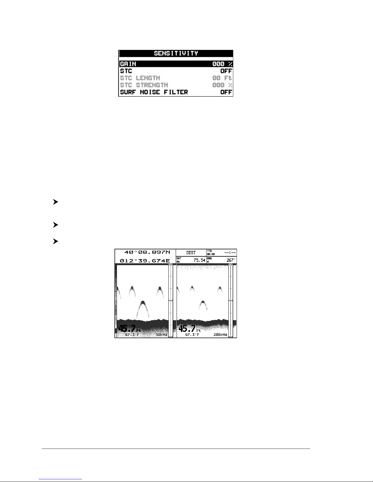
2.2.4 Zoom page
To display the zoomed Fish Finder page on the left half of the screen and the un-
zoomed Fish Finder Echogram on the right half of the screen, follow this procedure:
[MENU] + "PAGE" + [ENTER] + "FISH FINDER" + [ENTER] + "Zoom" +
[ENTER]
COLOR MAX 11/COLOR MAX PRO/COLOR MAX 15:
[DATA] + "FISH FINDER" + [ENTER] + "Zoom" + [ENTER]
TRAWL PLOT 12/TRAWL PLOT 12 SD:
[PAGE] + "FISH FINDER" + [ENTER] + "Zoom" + [ENTER]
Fig. 2.2.4 - Fish Finder Zoom Page
The Depth Cursor is shown only on the unzoomed Fish Finder Echogram.
The ZOOM IN and ZOOM OUT keys
When in this page pressing [ZOOM IN] changes to Zoom 4X, pressing [ZOOM
OUT] changes to Zoom 2X.
2.2.5 Chart/Fish page
To display the Chart page on the left half of the screen and the Fish Finder
Echogram on the right half of the screen, follow this procedure:
[MENU] + "PAGE" + [ENTER] + "FISH FINDER" + [ENTER] + "Chart/Fish"
+ [ENTER]
COLOR MAX 11/COLOR MAX PRO/COLOR MAX 15:
[DATA] + "FISH FINDER" + [ENTER] + "Chart/Fish" + [ENTER]
TRAWL PLOT 12/TRAWL PLOT 12 SD:
[PAGE] + "FISH FINDER" + [ENTER] + "Chart/Fish" + [ENTER]
Fig. 2.2.5 - Fish Finder Chart/Fish page
The MENU key (to change the active window)
When in Chart/Fish mode pressing [MENU]:

18 User Manual
♦if the focus (the active window) in on the Chart, the Main menu is
shown. Pressing again [MENU] opens the Fish Finder Setup menu and
moves the focus to the Fish Finder.
♦if the focus (the active window) in on the Fish Finder, the Fish Finder
Setup menu is shown. Pressing again [MENU] opens the Main menu
and moves the focus to the Chart.
NOTE When the focus is on the Chart, all keys behave as in standard chart mode.
2.2.6 Fish Finder and Radar pages ONLY FOR COLOR MAX 11/COLOR MAX PRO/COLOR
MAX WIDE E/COLOR MAX WIDE I/COLOR MAX SEALINK I/COLOR MAX SEALINK E/EXPLORER II Plus/
COLOR MAX 15/TRAWL PLOT 12/TRAWL PLOT 12 SD
To display the Radar page on the left half of the screen and the Fish Finder
Echogram on the right half of the screen, follow this procedure:
[MENU] + "PAGE" + [ENTER] + "FISH FINDER" + [ENTER] + "Radar/FF" +
[ENTER]
COLOR MAX 11/COLOR MAX PRO/COLOR MAX 15:
[DATA] + "FISH FINDER" + [ENTER] + "Radar/FF" + [ENTER]
TRAWL PLOT 12/TRAWL PLOT 12 SD:
[PAGE] + "FISH FINDER" + [ENTER] + "Radar/FF" + [ENTER]
Fig. 2.2.6 - Radar/FF page
Otherwise to display the Radar and Fish Finder Combo pages, follow this procedure:
[MENU] + "PAGE" + [ENTER] + "FISH FINDER" + [ENTER] + "Radar/FF/
Chart/Nav Data" + [ENTER]
COLOR MAX 11/COLOR MAX PRO/COLOR MAX 15:
[DATA] + "FISH FINDER" + [ENTER] + "Radar/FF/Chart/Nav Data" + [ENTER]
TRAWL PLOT 12/TRAWL PLOT 12 SD:
[PAGE] + "FISH FINDER" + [ENTER] + "Radar/FF/Chart/Nav Data" + [ENTER]
Fig. 2.2.6a - Combo page

19
User Manual
When in Split/Combo pages, the active view is highlighted by a focus (Yellow
frame). The keyboard commands are related to that focused view. To move the
focus press [MENU] twice.
2.3 ZOOM MODES
2.3.1 The Bottom Lock Zoom
The Bottom Lock Zoom mode is activated when the Fish Finder is in Auto Range or
Bottom Lock mode (see Par. 3.1.3) and the Variable Depth Marker (VDM) is not
displayed on the screen.
In Bottom Lock Zoom mode the Fish Finder Echogram is automatically moved up/
down as to keep the Bottom Line always visible in the lower half of the screen.
NOTE Moving the Cursor key up/down displays the Variable Depth Marker (VDM)
switching the Fish Finder in Marker Zoom mode.
2.3.2 The Marker Zoom
The Marker Zoom mode is activated either when the Fish Finder is in Manual
Range mode (see Par. 3.1) or the Depth Cursor is displayed on the screen.
In Marker Zoom mode the Fish Finder Echogram position is controlled by moving
the Variable Depth Marker (VDM) and pressing and holding [ENTER] for 1 second
on the selected position. Moving the Variable Depth Marker (VDM) over the top or
below the bottom of the screen, automatically moves up/down the current zoomed
Echogram view and re-position the Variable Depth Marker (VDM) at the center of
the screen.
NOTE Pressing [CLEAR] hides the Depth Cursor and if the Fish Finder is in Auto
Range or Bottom Lock mode switches into Bottom Lock Zoom mode.
2.4 SOUNDER ADJUSTMENTS WITH SOFT KEYS
When the Fish Finder page is active, by pressing one of the Soft Keys, the main
functions to adjust the Fish Finder are shown on the Soft Keys labels on the
screen. The Soft Keys labels disappear automatically if no keys are pressed after
5 seconds or by pressing [CLEAR].
The GAIN Soft Key
By pressing [GAIN]the Gain changes between AUTO GAIN and MANUAL GAIN.
If MANUAL GAIN, use the cursor left/right to adjust it: a bar with the % symbol is
displayed on the screen above the [GAIN]label.
If AUTO GAIN, use the cursor left/right to adjust the Gain Offset: a bar with the %
symbol is displayed on the screen above the [GAIN]label.
The RANGE Soft Key
By pressing [RANGE]the window switches to the next RANGE status: MANUAL,
BOTTOM LOCK and AUTO.
If MANUAL, use the cursor up/down to adjust the Depth value by 10ft time and
use the cursor left/right to adjust the Shift. When in meters the step is 2 meters
and it increases to 10 meters when the key is pressed for more than 1 second.
If BOTTOM LOCK, use the cursor up/down to adjust the Bottom Range value by
10ft at a time.
If AUTO RANGE, the Range value is set automatically by the ES and it cannot be
changed by the user.

20 User Manual
The STC Soft Key
The [STC] changes the STC value between OFF/SHORT/MID/LONG. The current
value of STC is shown on a window right over the [STC] label.
The FREQ Soft Key
By pressing [FREQ]it is possible to select the Frequency to which the Sensitivity
parameters are applied.
This option is available only in the Dual Frequency page.
2.5 INFO ON FISH FINDER: SYSTEM INFORMATION
If you want to know information about the Fish Finder connected, follow the
procedure:
[MENU] + "About..." + [ENTER]
A window will be shown with the desired information on the Fish Finder Library
row and on the Fish Finder module row.
XXXX V. X.yy R [GG/MM/YYYY]
8
BBFF 50/200
V2.1.333.2000 B [18/01/2008]
Fig. 2.5 - System Information page
2.5.1 The System Update menu
The System Update menu allows downloading the Fish Finder firmware into the
Fish Finder device. To select this menu follow the procedure:
[MENU] + "About..." + [ENTER] + [MENU] + "Update BBFF Firmware" +
[ENTER]
The current Fish Finder firmware version is shown in the System Update window
that appears on the screen.
Insert the C-CARD with the firmware in one of the chart plotter available slots,
and the press [ENTER] to update. Now select "YES" and press [ENTER] to confirm.
WARNING
Turn Off and after a few seconds turn On the ES502 in case of failed firmware
upload.

21
User Manual
3. Setup your Fish Finder
3.1 FISH FINDER SETUP MENU
The Fish Finder Setup menu provides access to additional functions, setup and
layout/data field options.
From the Fish Finder page, access this menu by pressing:
[MENU]
Fig. 3.1 - Fish Finder Setup menu
3.1.1 Preset Mode
Allows applying the following Fish Finder operating mode presets Fish and Cruise.
See the following table.
[MENU] + "PRESET MODE" + [ENTER]
Fish : Gain Mode = Auto, Range Mode = Auto, Frequency = do not change, Shift = 0, STC = Short if
Freq=200kHz and Mid if Freq=50kHz, Scrolling Speed = 10, Fish Symbols = Echo, A-Scope = On,
Surface Noise Filter = Off.
Cruise : Gain Mode = Auto, Range Mode = Auto, Frequency = do not change, Shift = 0, STC = Short if
Freq=200kHz and Mid if Freq=50kHz, Scrolling Speed = 10, Fish Symbols = Echo, A-Scope = On,
Surface Noise Filter = 4.
3.1.2 Gain Mode
Selects Auto or Manual.
[MENU] + "GAIN MODE" + [ENTER]
3.1.3 Range Mode
Selects among Manual, Auto Range and Bottom Lock. When in Manual Range
Mode it is possible to set Shift (the offset from the surface) (see Par. 3.1.6) and
Depth (see Par. 3.1.5) on which the Fish Finder shall operate. When in Auto
Range Mode the Fish Finder determines automatically the range as to keep the
bottom visible in the lower left of the screen. In this mode, Shift is always set to
0. In Bottom Lock Mode the Fish Finder automatically tracks the range around
the bottom specified by the Bottom Range value.
[MENU] + "RANGE MODE" + [ENTER]
3.1.4 Depth
This option is available only when Range Mode is Manual and it is disabled in Auto
Range and Bottom Lock Mode.
[MENU] + "DEPTH" + [ENTER]

22 User Manual
3.1.5 Shift
This option is available only when Range Mode is Manual and it is disabled in Auto
Range and Bottom Lock Mode.
[MENU] + "SHIFT" + [ENTER]
NOTE The bottom Range, Depth, Shift will apply to the currently selected frequency.
3.1.6 Bottom Range
This option is available when Range Mode is Bottom Lock.
[MENU] + "BOTTOM RANGE" + [ENTER]
3.1.7 Frequency
Allows you to choose the frequency between Auto, 50 kHz or 200 kHz when single
frequency page is selected.
[MENU] + "FREQUENCY" + [ENTER]
3.1.8 Interference Rejection
Selects a filter to remove interference from other Fish Finders.
[MENU] + "INTERF REJECT" + [ENTER]
3.1.9 Sensitivity
The Sensitivity menu is accessible both from the Fish Finder Setup menu and by
pressing [ENTER] when in Fish Finder pages. All settings in the Sensitivity menu
are related to the Frequency selected.
[MENU] + "SENSITIVITY" + [ENTER]
Fig. 3.1.9 - Fish Finder Sensitivity menu
NOTE The Frequency value is only displayed: to select the desired frequency see the
previous Par. 3.1.7.
3.1.9.1 Frequency
This option is available only in the Dual Frequency page. It allows you to select
the Frequency to which the Sensitivity parameters are applied.
3.1.9.2 Gain
Allows you to control the Gain of the unit's receiver. To see more details on the
screen, increase the receiver sensitivity by selecting a higher gain percentage. If
there is too much detail or if the screen is cluttered, lowering the sensitivity may
increase the clarity of the display.
3.1.9.3 STC
Sensitivity Time Constant: it is a time varying gain curve which attenuates the
sonar receiver gain in shallow water, increasing the gain gradually as the depth
increases. This is for the purpose of filtering out surface clutter.
3.1.9.4 STC Length
If STC is Custom, it is possible to change the Length of the Sensitivity Time
Constant.
Table of contents
Other Sitex Fish Finder manuals


