SitOnit Seating eBEAM User manual
C6547 Rev. A
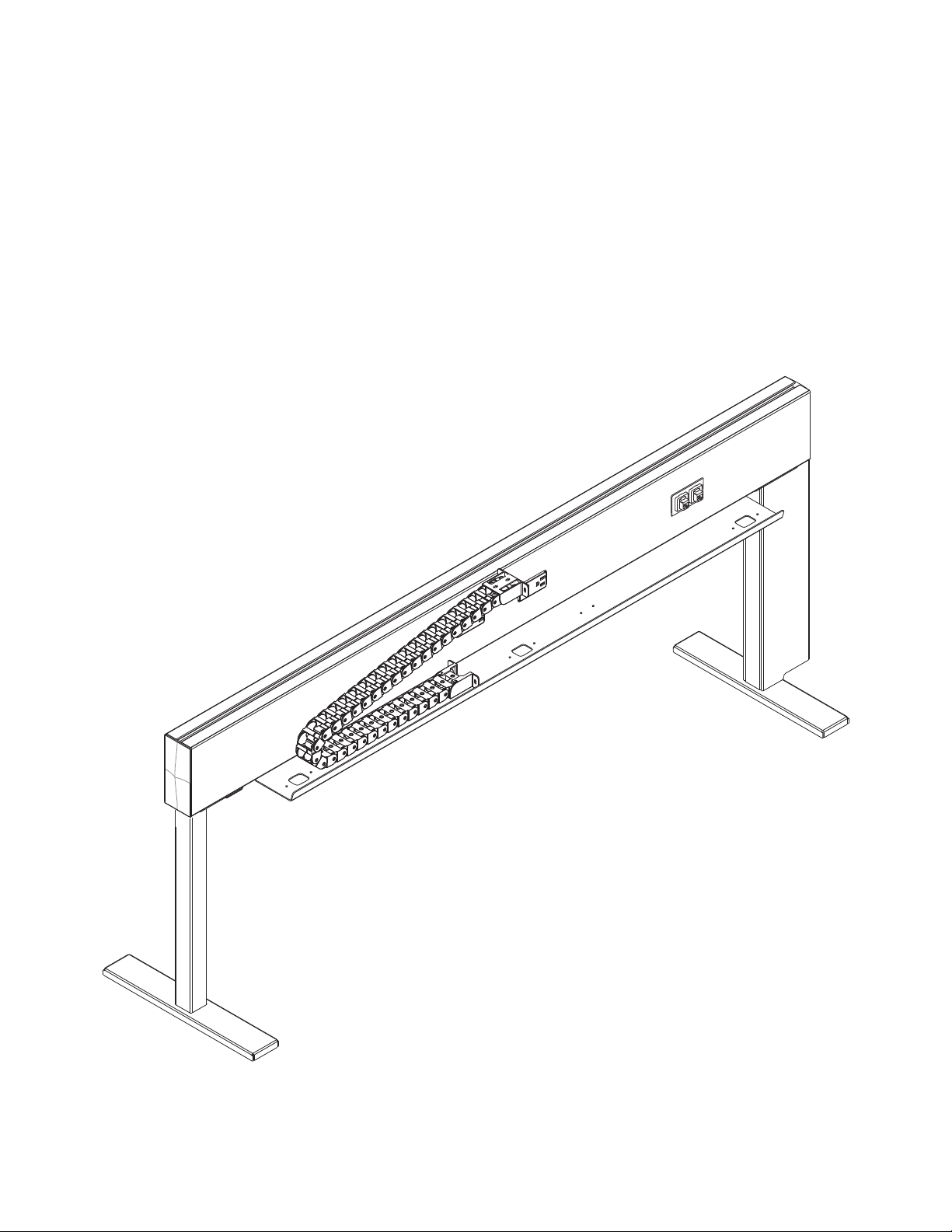
eBEAM
ASSEMBLY INSTRUCTIONS
eBEAM is a straightforward, streamlined solution for adding power to your workstations.
With adaptable legs, multiple beam lengths and cable management options that make it
practically mess-free, eBEAM is simply powerful (and powerfully simple).
To report any issues with this product, please contact our customer service department at (888) 274-8664.
For more information, visit www.sitonit.net
EBEAM ASSEMBLY INSTRUCTIONS
REQUIRED TOOLS
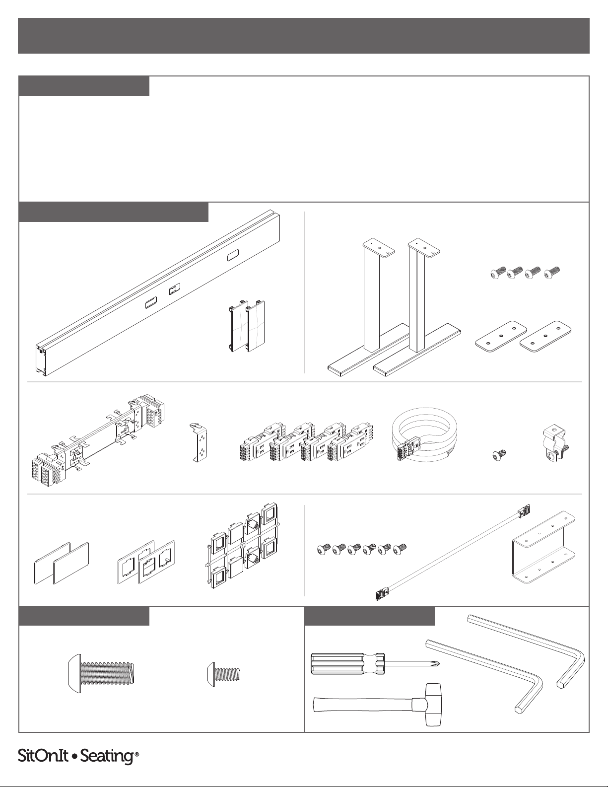
COMPONENT LIST
1:1 SCALE
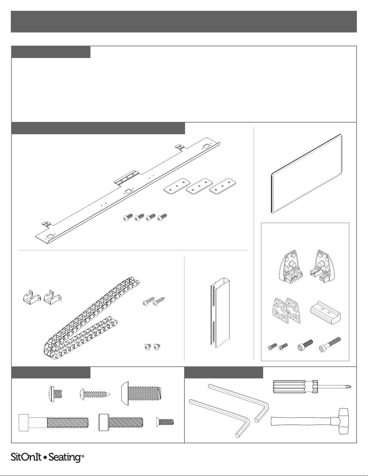
Beam
• Beam (1)
• End Cap (2)
Legs
• Leg (2)
• Mounting Plate (2)
• 5⁄16"–18 × ¾" Screw (4)
#2 Phillips Screwdriver
Non-Marring Mallet/Hammer
3⁄16" Hex L-Key
(Included)
Beam Legs
BEAM
POWER
DATA PACK GANGING
LEGS
Mounting Plates
Power
Distribution Harness
End Caps
POWER BEAM COMPONENTS
Middle Clip
Blank Faceplates Data Faceplates
Data
Adapter Tree
Power
• Power Distribution Harness (1)
• Middle Clip (1)
• Duplex Receptacles (4)
• Power Infeed (1)
• Hose Clamp (1)
• #10–24 × ⅜" Screw (1)
5⁄16"–18 × ¾" Screws
5⁄16"–18 × ¾"
#10–24 × ⅜" Screws
Ganging Bracket
Jumper
Component quantities shown are
for a standard 2-seat back-to-back
conguration.
Quantities will vary with user
specications. For more information,
see the table on page 22.
For accessory components,
see page 12.
Data adapters are not included.
See page 23 for a list of compatible jacks.
Included if two or more beams will be connected.
Power InfeedDuplex Receptacles
Data Pack
• Data Adapter Tree (1)
• Blank Faceplate (2)
• Data Faceplate (2)
Ganging (If Applicable)
• Ganging Bracket (1)
• #10–24 × ⅜" Screw (6)
• Jumper (1)
#10–24 × ⅜"
Hose Clamp
#10–24 × ⅜" Screw
⅛" Hex L-Key
(Included)
Installation may not use all of the provided screws or mounting plates.
2
To report any issues with this product, please contact our customer service department at (888) 274-8664.
For more information, visit www.sitonit.net
EBEAM ASSEMBLY INSTRUCTIONS
STEPS
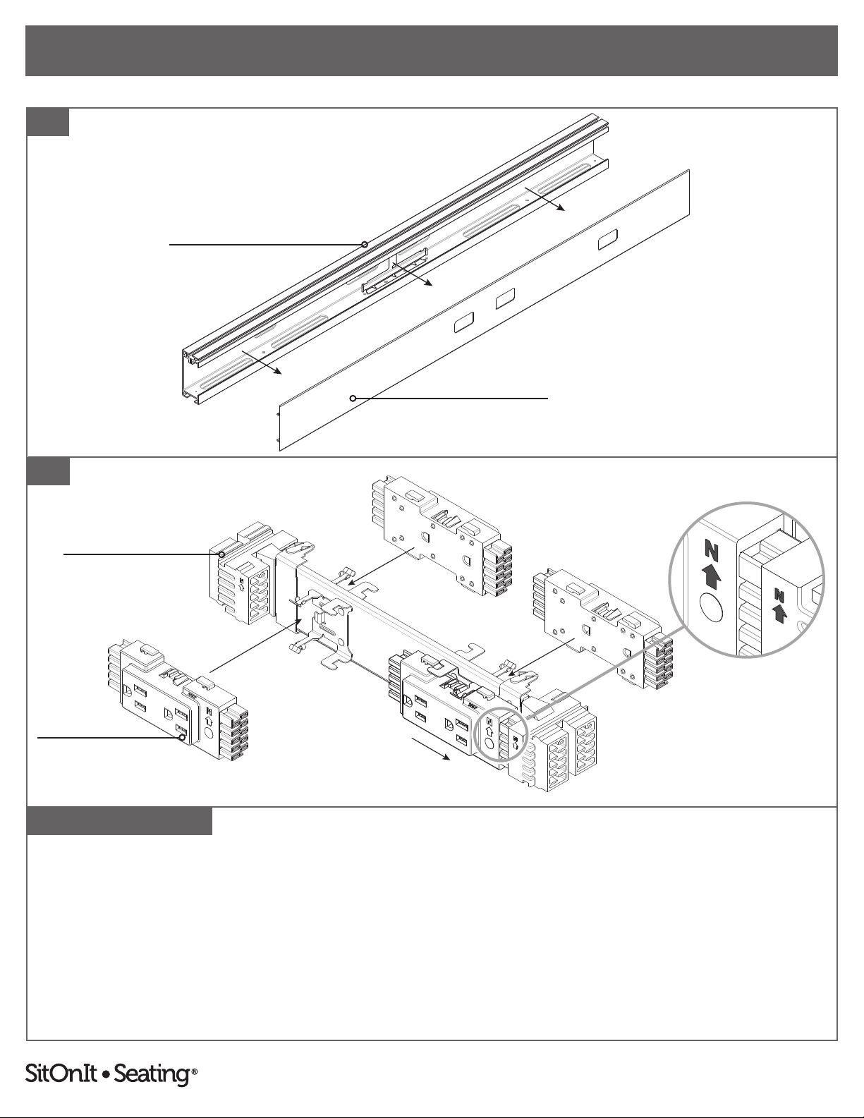
1
Note: We recommend reading these instructions in their entirety and laying all components out in advance.
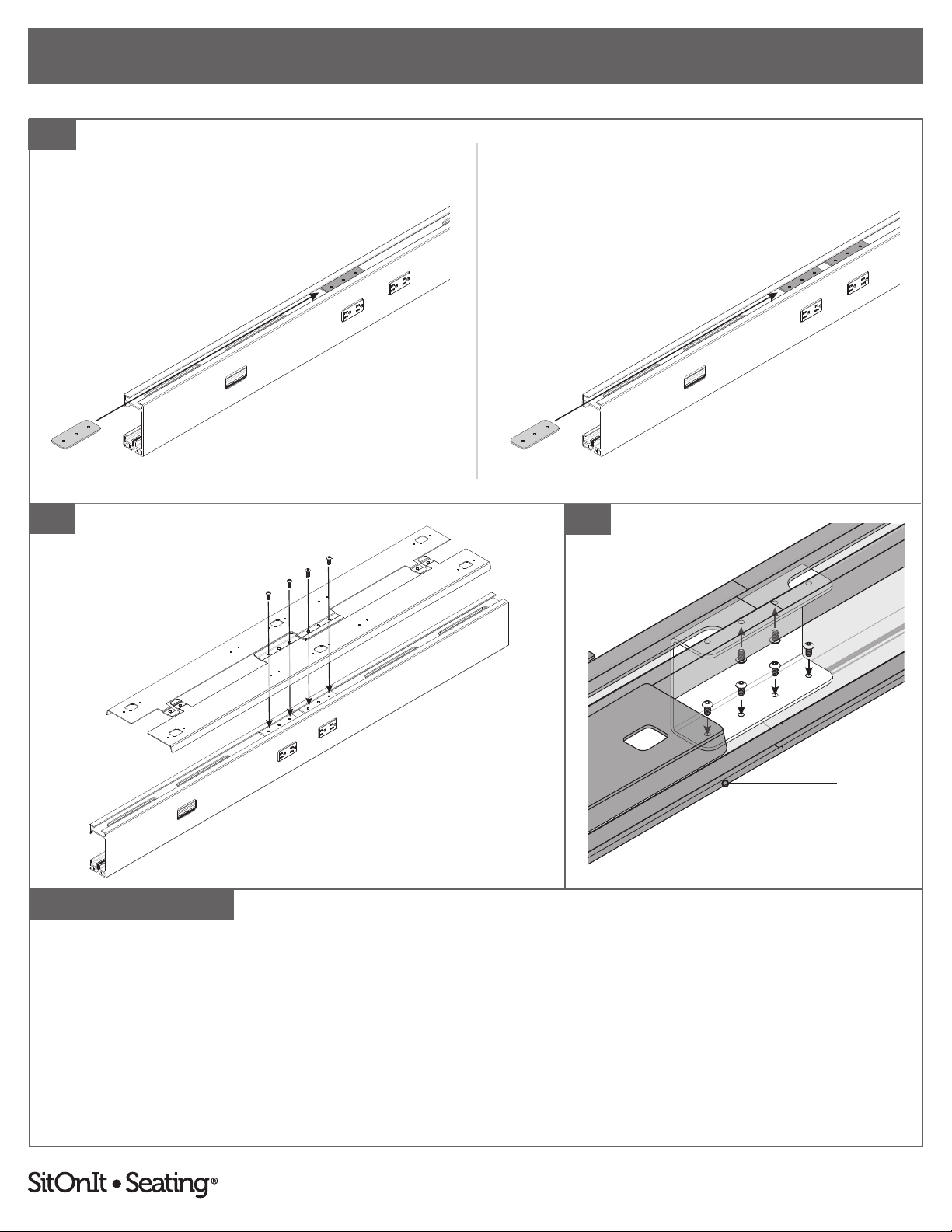
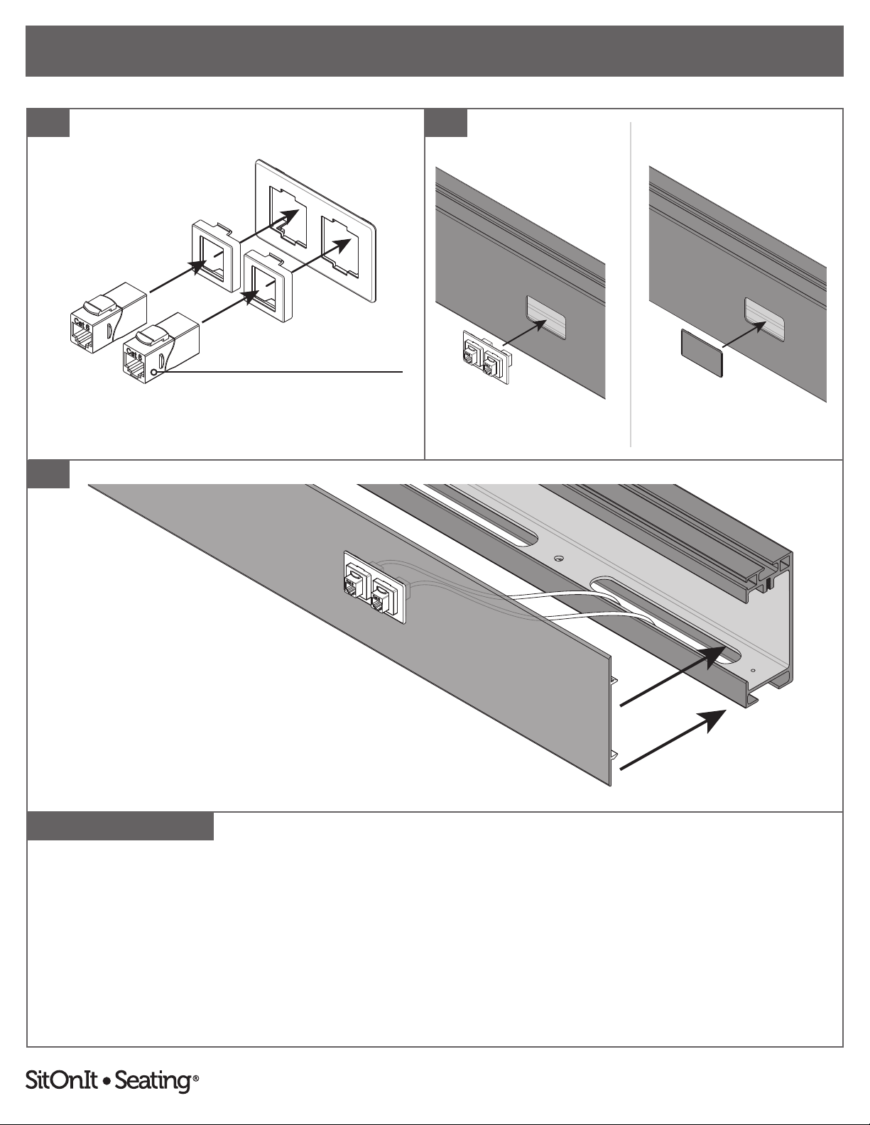
1. Remove cover from beam and set aside.
2. If duplex receptacles were purchased, set them into the power distribution harness with the arrows pointing up, then slide
outwards to snap them into place.
Beam
Cover
Duplex Receptacle
Power Distribution Harness
SNAP
2
3
To report any issues with this product, please contact our customer service department at (888) 274-8664.
For more information, visit www.sitonit.net
EBEAM ASSEMBLY INSTRUCTIONS
STEPS
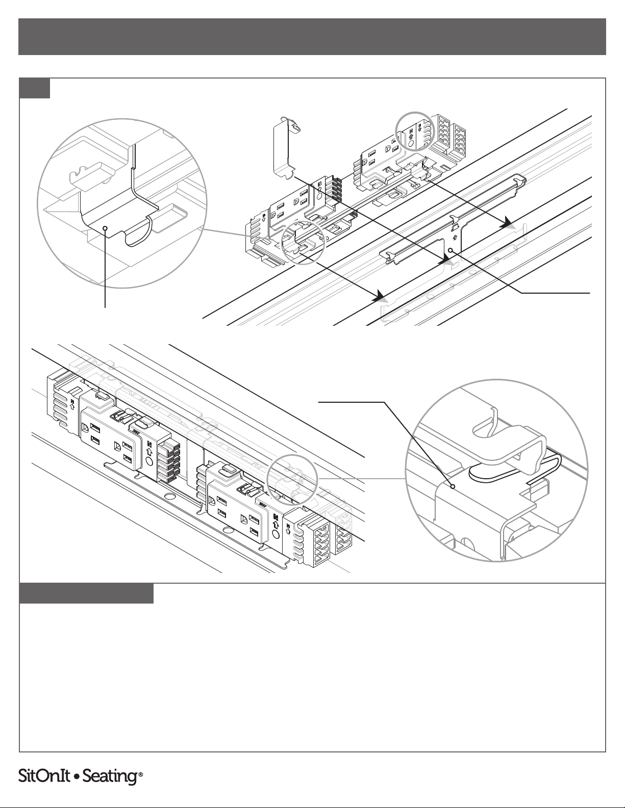
3
Bottom Harness Clip
Mounting Bracket
Top Harness Clip
To attach a distribution harness:
3. Align distribution harness with the pre-installed mounting bracket, ensuring that the arrows on both the distribution harness
and the duplexes point up. Hook the bottom harness clips rst, then rotate slightly and apply pressure to snap the top
harness clips into the mounting bracket. The mounting bracket is pre-installed on the inside center of the beam.
Place the middle clip over the distribution harness and attach it to the mounting bracket, hooking the bottom rst, before
snapping the top of the clip into mounting bracket.
4

To report any issues with this product, please contact our customer service department at (888) 274-8664.
For more information, visit www.sitonit.net
EBEAM ASSEMBLY INSTRUCTIONS
STEPS
Bottom Slot
Infeed would run up this side
Beam is shown upside-down. Beam is shown upside-down. Beam is shown upside-down.
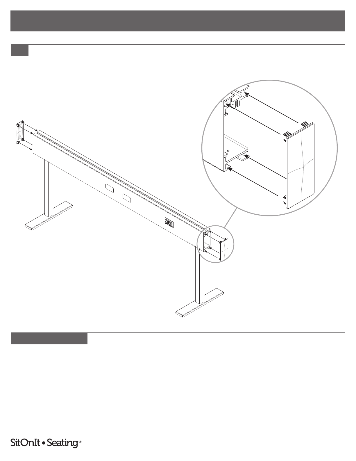
For leg installation without wire trays, complete steps 4–6 below.
For leg installation with wire trays, see steps 7–11 (pages 6–7).
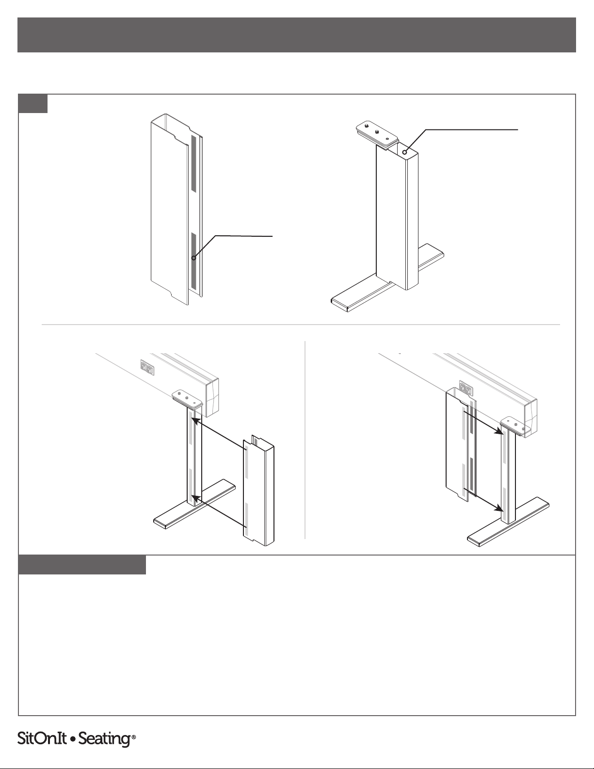
4. Flip the beam upside-down and slide in one mounting plate per leg, aligning them to the desired locations, leaving at least a
3" gap in one of the bottom slots for the power infeed and ¾" spacing from the open ends of the beam for the end caps.
5. If attaching multiple beams: From within the ganging bracket, inside of the beam (shown inverted above), fasten the
ganging bracket using the ⅛" hex L-key to install two #10–24 × ⅜" screws up into the inside bottom of the beam and four
#10–24 × ⅜" screws down into the inside top of the beam.
6. Place the legs in position and use the 3⁄16" hex L-key to secure them in place with two 5⁄16"–18 × ¾" screws per mounting
bracket. Turn beam upright. Note: Legs can be mounted in two dierent directions.
4
RECOMMENDED LEG PLACEMENT
5
6
Top of Beam
Infeed would run up this side
LEG FACES IN LEG FACES OUT
Beam is shown upside-down.
5
To report any issues with this product, please contact our customer service department at (888) 274-8664.
For more information, visit www.sitonit.net
EBEAM ASSEMBLY INSTRUCTIONS
STEPS
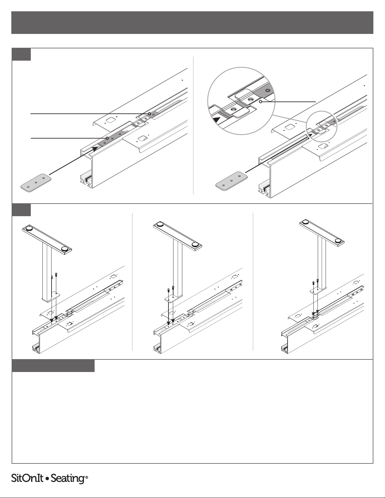
For leg installation with wire trays complete steps 7–11:
7. Flip the beam upside-down and slide in one mounting plate per wire tray, aligning them with the central holes of the beam.
8. Place the wire tray(s) in position and then secure the trays to the mounting plates by using the 3⁄16" hex L-key to fasten two
5⁄16"–18 × ¾" per mounting plate.
9. If attaching multiple beams: From within the ganging bracket, inside of the beam (shown inverted above), fasten the
ganging bracket using the ⅛" hex L-key to install two #10–24 × ⅜" screws up into the inside bottom of the beam and four
#10–24 × ⅜" screws down into the inside top of the beam.
9
7
8
Top of Beam
Beam is shown upside-down.
Beam is shown upside-down.
Beam is shown upside-down.
SINGLE-SIDED BACK-TO-BACK
6
To report any issues with this product, please contact our customer service department at (888) 274-8664.
For more information, visit www.sitonit.net
EBEAM ASSEMBLY INSTRUCTIONS
STEPS
Beam is shown upside-down.
Beam is shown upside-down.
Beam is shown upside-down.Beam is shown upside-down.
Beam is shown upside-down.
Beam is shown upside-down.
Beam is shown upside-down.
10
11
10. If legs share mounting plates with the wire tray(s): Slide in one mounting plate per leg and align them to the outer wire
tray tabs. (Use this installation option with the mounting plate closest to the infeed when using a 48" beam.)
If legs do not share mounting plates with the wire tray: Slide in one mounting plate for each leg and set of wire tray tabs.
The mounting plates for the legs can be placed inside or outside the wire trays' outer mounting plates.
Note: Leave at least a 3" gap in the bottom slot for the infeed and ¾" spacing from the open ends of the beam for the end
caps. Some mounting plates or screws may be left over after installation.
11. Place the legs in position and use the 3⁄16" L-hex key to secure the legs and outer wire tray mounting plates in place with two
5⁄16"–18 × ¾" per mounting bracket. Turn beam upright. Note: Legs can be mounted in two dierent directions.
SEPARATE MOUNTING PLATE SHARED MOUNTING PLATES
Mounting Plate for Leg
Mounting Plate for Wire Tray(s)
MOUNTING PLATE FACES IN MOUNTING PLATE FACES OUT SHARED MOUNTING PLATE
Wire Tray Tabs
7
To report any issues with this product, please contact our customer service department at (888) 274-8664.
For more information, visit www.sitonit.net
EBEAM ASSEMBLY INSTRUCTIONS
STEPS
12
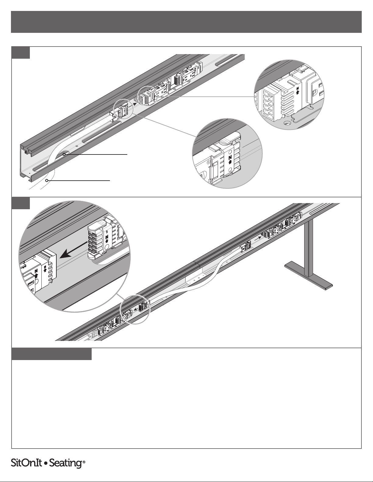
12. Route power infeed through one of the bottom slots of the beams and plug the end of the power infeed into the nearest
distribution harness, ensuring that the arrows on both the distribution harness and the power infeed point upwards.
13. If attaching multiple beams together: Plug one end of the jumper into each beam's distribution harness, ensuring that
the arrows on both the distribution harnesses and the jumper point up.
Note: The jumper and infeed can be plugged in next to each other if the infeed is not on the outer distribution harness.
Bottom Slot
Power Infeed
13
8
To report any issues with this product, please contact our customer service department at (888) 274-8664.
For more information, visit www.sitonit.net
EBEAM ASSEMBLY INSTRUCTIONS
STEPS
Dept. Technical reference
14
16
15
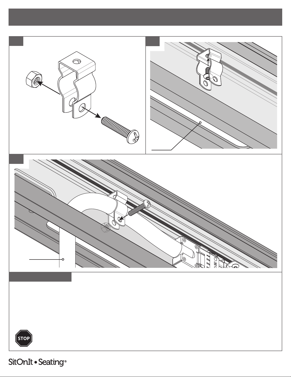
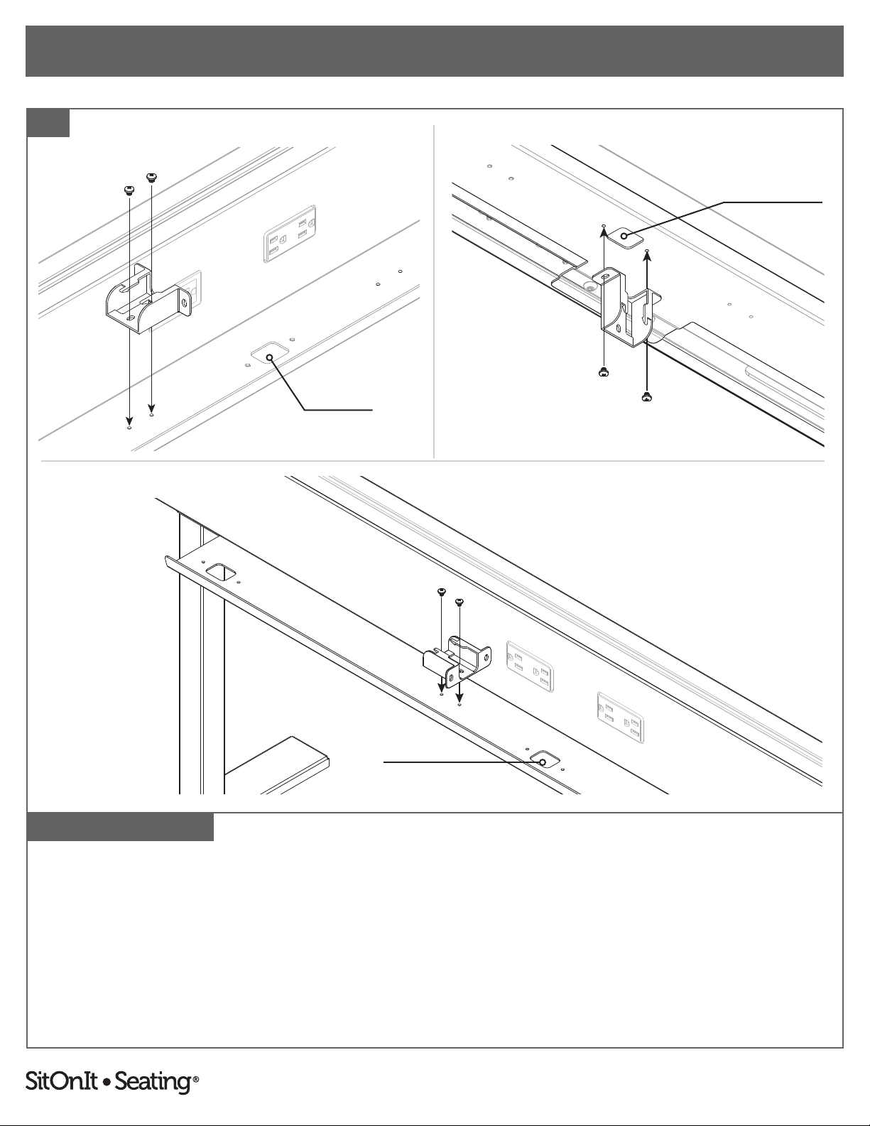
14. Remove the ¼"–20 × 1¼" screw and ¼"–20 × ¼" hex nut from the pre-attached hose clamp assembly.
15. Position the hose clamp above one of the bottom slots and fasten it to the thread feature on the upper inside of beam
with a #10–24 × ⅜” screw using the ⅛" hex L-key.
16. Hold the power infeed within the hose clamp opening and slide the ¼"–20 × 1¼" screw through the hose clamp holes.
Then tighten the ¼"–20 × ¼" hex nut onto the screw using a #2 Phillips screwdriver.
Connection to building wiring must be done by a qualied electrician.
See page 23 for 4-2-2 wiring schematic.
Power Infeed
Bottom Slot
9
To report any issues with this product, please contact our customer service department at (888) 274-8664.
For more information, visit www.sitonit.net
EBEAM ASSEMBLY INSTRUCTIONS
STEPS
17. Break o applicable data adapters from tree and snap into data faceplates, then snap in respective data modules, etc. (not
supplied).
18. Snap blank faceplates and/or data faceplates into window cutouts on the beam and beam cover.
19. Route data cables through bottom slot of the beam and connect into data modules. Then align and snap the beam cover
back onto the beam.
19
17 18
Data Modules Are Not Included
DATA FACEPLATE BLANK FACEPLATE
10
To report any issues with this product, please contact our customer service department at (888) 274-8664.
For more information, visit www.sitonit.net
EBEAM ASSEMBLY INSTRUCTIONS
STEPS
20
BLANK FACEPLATE
If no screens were purchased, complete step 20 below to nish the beam.
For optional screen assembly, complete steps 21–26 and continue from there.
20. Align end caps with square shapes and bottom opening at each end of the beam and pound ush into place with a non-
marring mallet/hammer, then peel o protective lm.
If no additional accessories were purchased, the beam is now complete.
For other optional accessories, reference:
Power infeed cover installation (page 16).
Vertical wire manager (pages 17–20).
11
To report any issues with this product, please contact our customer service department at (888) 274-8664.
For more information, visit www.sitonit.net
EBEAM ACCESSORY ASSEMBLY INSTRUCTIONS
REQUIRED TOOLS
COMPONENT LIST
1:1 SCALE
Wire Tray
Wire Manager
Horizontal Wire Tray
(Per Side)
• Wire Tray (1)
• Mounting Plate (3)
• 5⁄16"–18 × ¾" Screw (4)
#2 Phillips Screwdriver
5 mm Hex L-Key
3⁄16 Hex L-Key
HORIZONTAL WIRE TRAY (EACH): PAGE 6–7
VERTICAL WIRE MANAGER (EACH): PAGE 17–20 POWER INFEED
COVER: PAGE 16
SCREEN: PAGES 13–15
Mounting Plates
OPTIONAL ACCESSORY COMPONENTS
#8 × ⅝" Screws
5⁄16"–18 × ¾" Screws
#8 × ⅝" 5⁄16"–18 × ¾"#10–24 × 3⁄16"
#10–24 × 3⁄16" Screws
Screen
• Screen
Per Mount:
• U-Bracket (2 Halves)
• Mounting Bar (1)
• M4 × 12 mm Screw (2)
• M6 × 20 mm Screw (1)
• M6 × 35 mm Screw (1)
• Gasket (2)
M6 × 35 mm M6 × 20 mm M4 × 12 mm
PER MOUNT
U-Bracket (Side A) U-Bracket (Side B)
M6 × 20 mm M6 × 35 mm
Mounting Bar
M4 × 12 mm
Screen
Wire Manager Clips
Component quantities are per accessory.
Quantities will vary with user
specications. For more information,
see the table on page 22.
Installation may not use all of the provided screws or mounting plates.
Vertical Wire Manager
(Each)
• Wire Manager (1)
• Wire Manager Clip (2)
• #10–24 × 3⁄16" Screw (2)
• #8 × ⅝" Screw (2)
Power Infeed Cover
• Power Infeed Cover (1)
Power Infeed Cover
Gaskets
Non-Marring Mallet/Hammer
12
To report any issues with this product, please contact our customer service department at (888) 274-8664.
For more information, visit www.sitonit.net
EBEAM ACCESSORY ASSEMBLY INSTRUCTIONS
STEPS
21
DOODLE AND SECTOR SCREENSMOTIF SCREENS
22
Steps 21-25: Parts and instructions are per mount. There are two mounts included with 48" screens or three mounts included with 60"–72" screens.
Highest Point Highest Point
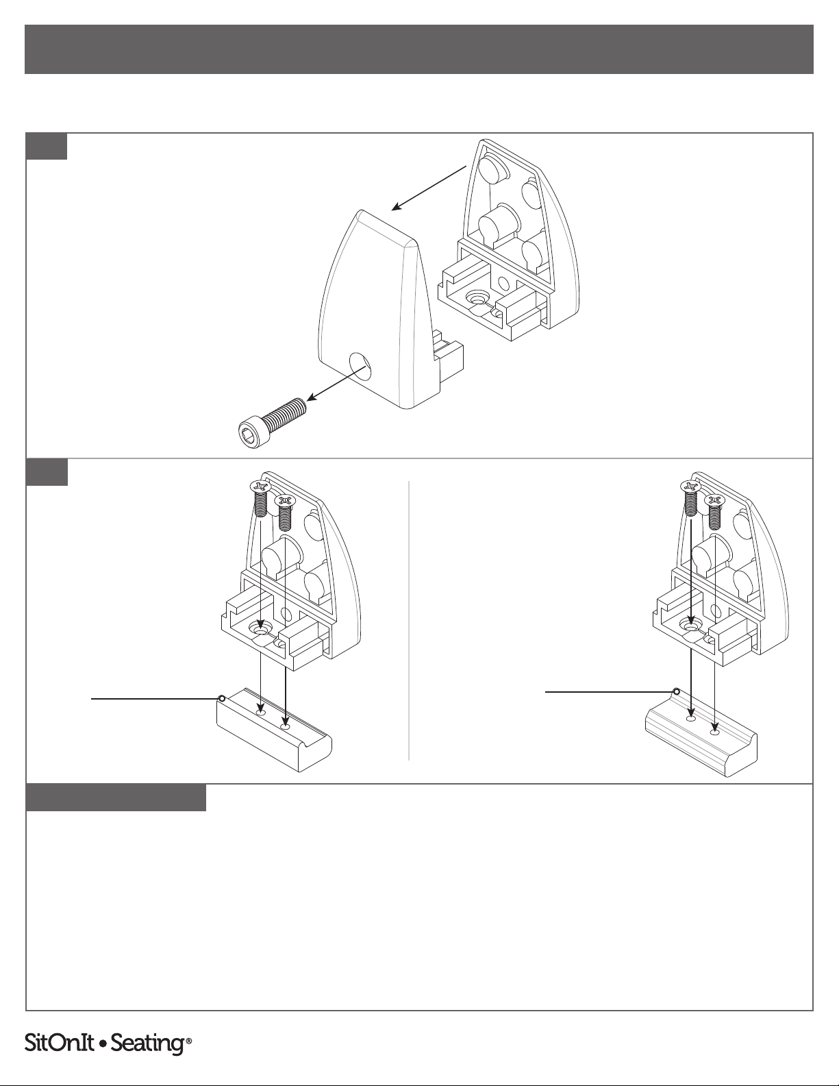
21. Separate U-bracket halves.
22. One side of the U-bracket (side A) has screw holes. Loosely attach the A side of the U-bracket to the mounting bar
using two M4 × 12 mm screws and a #2 Phillips screwdriver.
Note: Mounting bar direction varies with screen material. Rotate appropriately. See above.
13

To report any issues with this product, please contact our customer service department at (888) 274-8664.
For more information, visit www.sitonit.net
EBEAM ACCESSORY ASSEMBLY INSTRUCTIONS
STEPS
23
DOODLE AND SECTOR SCREENSMOTIF SCREENS
Steps 21-25: Parts and instructions are per mount. There are two mounts included with 48" screens or three mounts included with 60"–72" screens.
25
M6 × 35 mm Screw M6 × 20 mm Screw
24
23. Slide the U-bracket/mounting bar assemblies from the end of the beam into position. Tighten the M4 × 12 mm screws
with a #2 Phillips screwdriver.
24. Slide the B side of the U-bracket onto the A side. Attach the two sides together using the M6 screw that is appropriate for
the screen material and a 5 mm hex L-key. Do not close. Make sure to leave a gap for the screen.
25. First, insert the gaskets, pressing them against the inside of both halves of the U-bracket. Then insert the screen into the
assembled mount. Close the U-bracket by tightening the appropriate M6 screw with the 5 mm L-hex key. Continue until
the screen is secure.
14

To report any issues with this product, please contact our customer service department at (888) 274-8664.
For more information, visit www.sitonit.net
EBEAM ACCESSORY ASSEMBLY INSTRUCTIONS
STEPS
26
26. Align end caps with square shapes and bottom opening at each end of the beam and pound ush into place with a non-
marring mallet/hammer, then peel o protective lm.
If no additional accessories were purchased, the beam is now complete.
For other optional accessories, reference:
Power infeed cover installation (page 16).
Vertical wire manager (pages 17–20).
15
To report any issues with this product, please contact our customer service department at (888) 274-8664.
For more information, visit www.sitonit.net
EBEAM ACCESSORY ASSEMBLY INSTRUCTIONS
STEPS
MOUNTING PLATE FACES INWARD MOUNTING PLATE FACES OUTWARD
Hook and Loop
Space for Infeed and Data Cables
27. For optional power infeed cover assembly: To install the infeed cover, remove backing from all pieces of the hook and
loop. Slide over, position around legs and cables. Provide pressure onto both sides of the exterior of the infeed cover for at
least 30 seconds to set the hook and loop adhesive.
Note: The open end of the infeed cover will face the mounting plate direction.
27
16

To report any issues with this product, please contact our customer service department at (888) 274-8664.
For more information, visit www.sitonit.net
EBEAM ACCESSORY ASSEMBLY INSTRUCTIONS
STEPS
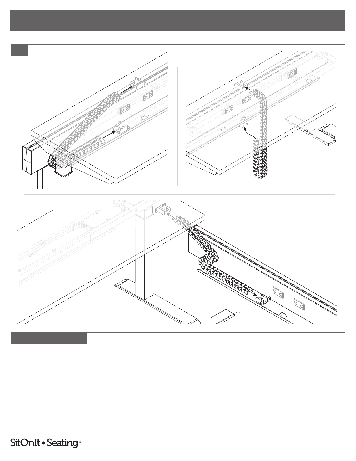
For optional vertical wire manager assembly: choose one of the installation styles above. Then, complete steps 28–30.
FINISHED
LATERAL INSTALLATION
FINISHED
PERPENDICULAR INSTALLATION
FINISHED
VERTICAL INSTALLATION
17
To report any issues with this product, please contact our customer service department at (888) 274-8664.
For more information, visit www.sitonit.net
EBEAM ACCESSORY ASSEMBLY INSTRUCTIONS
STEPS
28. Vertical installation: Attach the rst wire manager clip to the underside of the wire tray using two #10–24 × 3⁄16" screws
and a #2 Phillips screwdriver. Align to one of the three wire tray cut outs.
Lateral or perpendicular installation: Attach the rst wire manager clip to the top side of the wire tray using two
#10–24 × 3⁄16 screws and a #2 Phillips screwdriver. Align to a set of predrilled holes, found left or right of center.
28
Wire Tray Cutout
LATERAL INSTALLATION VERTICAL INSTALLATION
Wire Tray Cutout
Wire Tray Cutout
Underside of wire tray is shown.
PERPENDICULAR INSTALLATION
18

To report any issues with this product, please contact our customer service department at (888) 274-8664.
For more information, visit www.sitonit.net
EBEAM ACCESSORY ASSEMBLY INSTRUCTIONS
STEPS
LATERAL INSTALLATION VERTICAL INSTALLATION
Back Table Edge
29
29. Attach the second wire manager clip to the underside of the adjacent table top and use a Phillips #2 driver to fasten with
two #8 × ⅝" wood screws.
Snap the ends of the carrier into the installed wire management clips.
PERPENDICULAR INSTALLATION
Back Table Edge
Back Table Edge
19
To report any issues with this product, please contact our customer service department at (888) 274-8664.
For more information, visit www.sitonit.net
EBEAM ACCESSORY ASSEMBLY INSTRUCTIONS
STEPS
30
Note: To change the direction of the the wire management curvature, links can be detached and rotated 180º.
LATERAL INSTALLATION
PERPENDICULAR INSTALLATION
VERTICAL INSTALLATION
20
Table of contents


