Siyang 380J-3 User manual

SIYANG
四洋
R
380J-3
MARINE DIESELENGINE SET
OPERATION MANUAL
EASTCHINASHIPBUILDINGINSTITUTE FACTORY
December2003

EAST CHINA SHIPBUILDING INSTITUTE FACTORY
1
SIYANG
四洋
R
CONTENTS
1.General precautions·························································································· 1
2.Introduction······································································································· 2
Fig 380J-3 marine diesel engine set overall dimension ······························· 3
2.1 Description of the engine set···································································· 4
3.0 General engine data······················································································· 5
4.0 Main structure of engine··············································································· 6
4.1 Fuel system································································································ 6
4.2 Lubrication system ··················································································· 6
4.3 Cooling system ························································································· 7
4.4 Electric system ·························································································· 8
4.5 Gearbox ····································································································· 8
4.6 Electrical diagram····················································································· 9
4.6.1 Electric system parts description························································ 12
4.6.2 Instruments panel················································································· 12
4.7 Starting precautions ················································································ 12
4.8 Check before starting·············································································· 12
5. Operation of engine······················································································· 12
5.1Starting······································································································ 12
5.2Starting by Spring starter (if installed) ··················································· 13
5.3 Operation ································································································· 15
5.4 Stopping··································································································· 15
6.Routine maintenance ····················································································· 15
6.1 Initial attention························································································· 15
6.2 Routine maintenance periods ································································ 16
6.3 Lubrication oil specification ·································································· 16
6.4 Gearbox oil specification ······································································· 17
6.5 Main spanner torque setting··································································· 17
6.6 Tighten sequence for cylinder heads bolts············································ 18
6.7 Check of lubrication oil level································································· 18
6.8 Lubrication oil change············································································ 18
6.9 Alternator belt tension············································································· 18

EAST CHINA SHIPBUILDING INSTITUTE FACTORY
2
SIYANG
四洋
R
6.10 Gearbox oil check and change ···························································· 18
6.11 Priming the fuel system········································································ 18
6.12 Drain the coolant··················································································· 19
6.13 Changing fuel filter element ································································ 19
6.14 Idling speed adjustment ······································································· 19
6.15 Valve clearance adjustment ································································· 19
6.16 Starting and running the engine while the lifeboat
is hooked in davits or free fall rig ························································ 19
6.17General precaution about electrical system········································· 19
6.18Stroage ···································································································· 20
7. Trouble shooting···························································································· 21
7.1 Difficult in starting the engine ······························································· 21
7.2 Insufficient output ··················································································· 21
7.3 Black smoking from exhaust································································· 22
7.4 Low lube oil pressure ············································································· 22
7.5 Engine knocking····················································································· 22
7.6 Engine overheating················································································· 23
7.7 Engine over speed or override······························································· 23
Appendix 1:380J-3 diesel engine set delivery list·········································24
Appendix 2:Tools supplied with 380J-3 marine diesel engine set ···········24
Appendix 3:Spare parts supplied with 380J-3 marine diesel engine set ····25

EAST CHINA SHIPBUILDING INSTITUTE FACTORY
1
SIYANG
四洋
R
1.GENERALPRECAUTIONS
⑴. Ensure that the engine is securely mounted.
⑵.Ensure that the ventilation and combustion air dusts are not obstructed.
⑶.Keep the engine and surrounding areas clean.
⑷.Never allow any part of the body to come into contact with high
pressure fuel oil when testing injection equipment.
⑸.Avoid contact with exhaust pipe when the engine is, or has recently
been running .These parts can be very hot and can cause severe burns.
⑹.Rectify all fuel water and oil leaks as soon as possible.
⑺.Isolate the battery when working on the engine.
⑻.All drive belts must receive regular attention.
⑼.Keep electrical contacts free from corrosion etc by smearing them with
petroleum jelly.
⑽.Batteries under charge release explosive gases, therefore the battery
compartment must be well ventilated at all times. Never allow any
smoking, sparks or flames near the batteries.
⑾.Wear protective goggles when handing liquids which is harmful to
eyes, for example, battery acid. If any of these substances are splashed in
the eyes, wash out thoroughly with clean water.
⑿Many liquids used in engines are harmful if taken internally .In the
event of accidentally swallowing oil, fuel, antifreeze or battery acid obtain
medical assistance immediately.

EAST CHINA SHIPBUILDING INSTITUTE FACTORY
2
SIYANG
四洋
R
2.INTRODUCTION
The SIYANG make marine diesel engine set, type 380J-3 is based on
380C diesel engine and adapted for lifeboat Propulsion conforming to the
latest requirements include SOLAS 1974,1996 Amendments.
It is essential that the operators read carefully the main points in this
manual before the engine is put into service.
Reference is made to:
“CHECKS BEFORE STARTING” “STARTING” “OPERATION” and
“STOP” .
The engine must be able to start and operate under the most severe
conditions. Therefore the engine set must be carefully maintained in
accordance with this manual.
The information , specification, illustrations, instructions and statements
contained within this publication are given with our best intentions and are
believed to be correct at the time going to press. As our continued technical
development, We reserve the right to amend any technical information with
or without prior notice.
While every effort is made to ensure the accuracy of the particulars
contained within this publication neither the manufacturer or dealer shall in
any circumstances be held liable for any inaccuracy or the consequences
thereof.
User of this manual are advised that the specification details apply to
380J-3 engine set and not to any one particular engine. In case of difficulty,
consult East China Shipbuilding Institute Factory, China or a local
distributor for further advice and technical assistance.
The information given is subject to the company’s current condition and
is for the assistance of users and is based upon results obtained from tests
carried out at the place of manufacture. Our company doesn’t guarantee that
the same results will be obtained elsewhere under different conditions.
When purchasing parts, or giving instruction for the clients repairs,
please refer to engine part catalogue and specify ESCI Factory. Our
company can not be responsible for any damage arising from the parts that
have not been supplied by our company.
EAST CHINA SHIPBUILDING INSTITUTE FACTORY
3
SIYANG
四洋
R
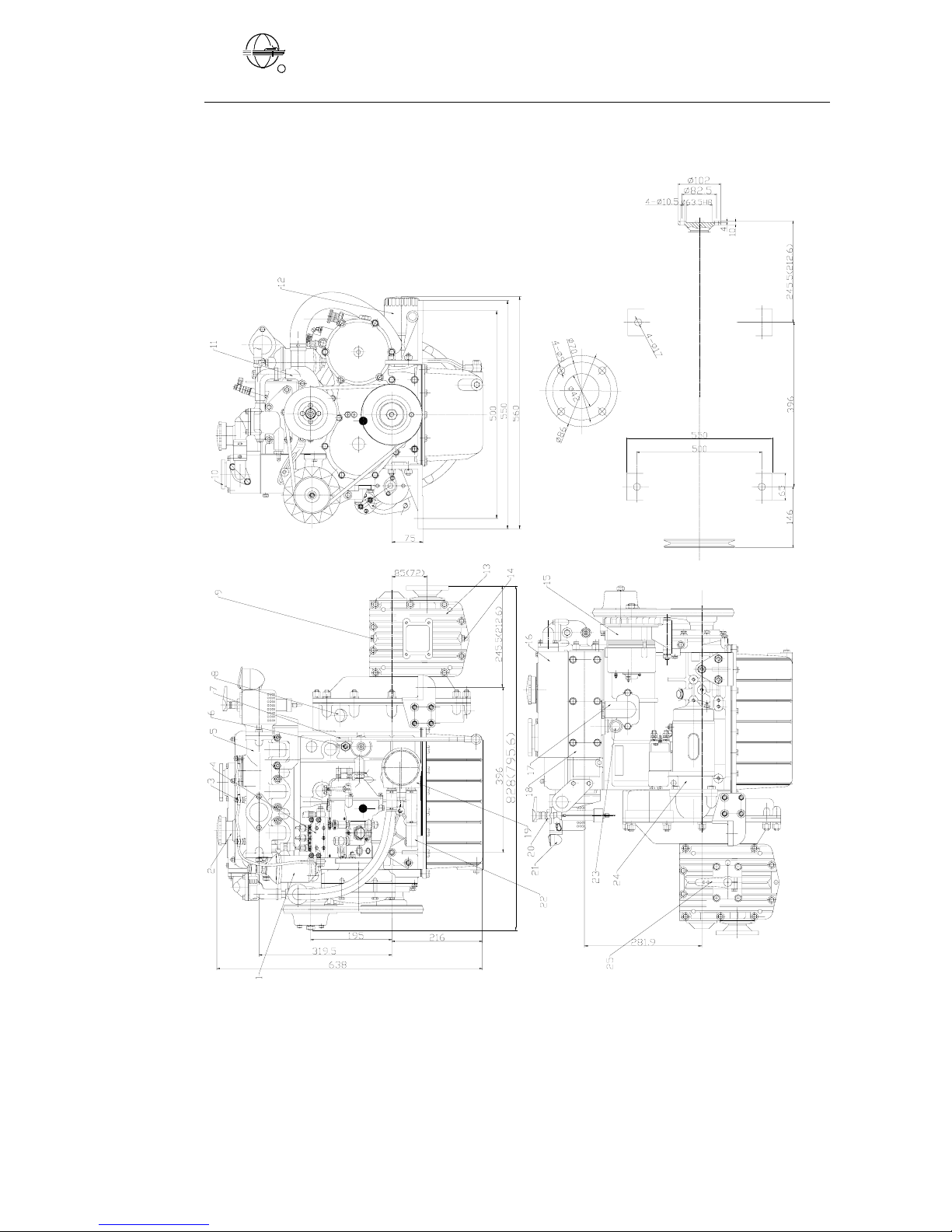
Exhaust flange
Note:Thedimensioninbracketisonlyformatching ZF12Mgearbox.
Fig.380J-3 marine diesel engine set overall dimension

EAST CHINA SHIPBUILDING INSTITUTE FACTORY
4
SIYANG
四洋
R
2.1 DESCRIPTION OFTHE ENGINE SET
1. Fuel filter
2. Breather
3. Fuel injector
4. Injection pump
5. Inlet manifold
6. Outlet cock
7. Lube oil dipstick
8. Tachometersensor
9. Gearbox dipstick
10.Expansion tanker cap
11.Fresh waterpump
12.Lube oil filter
13.Gearbox
14.Gearbox oil screw
15.Alternator
16.Expansion tanker
17.Lube filling cap
18.Exhaust body
19.Lube cooler
20.Either pump
21.Starting liquid reservoir
22.Water inlet pipe
23.Water outlet pipe
24.Starting motor
25.Gearbox handle

EAST CHINA SHIPBUILDING INSTITUTE FACTORY
5
SIYANG
四洋
R
3. GENEARALENGINE DATA
Type 380J-3
Model In line, vertical, water cooled
four stroke
Combustion chamber Direct injection
Number of cylinders 3
Bore×stroke (mm) 80×90
Total displacement (liters) 1.357
Firing order 1→3→2
Compression ratio 18:1
Rated output (kw/rpm) 20.6/2800
Fuel oil consumption at rated output (g/kw·h) ≤255
Lube oil consumption at rated output (g/kw·h) ≤2.72
Air consumption in 10 minutes (m3) 16.148
Lubrication method Splashed and forced
Method of cooling Water coolant
Direction of rotation Counter clockwise
(Looking on flywheel end)
Method of starting Electric option spring starter
Method of operation Mechanical direct translating
or flexible shaft remote operation
Exhaust temperature at rated output (℃) ≤550
Overall dimension (L×W×H) (mm) 828 (796)×560×638
Weight (kg)200
Note: the dimension in bracket is only formatching ZF12M gearbox

EAST CHINA SHIPBUILDING INSTITUTE FACTORY
6
SIYANG
四洋
R
4.MAIN STRUCTURE OFENGINE
4.1 FUELSYSTEM
The fuel system are important controlling components of the diesel
engine. They are composed of injectors, fuel filter, injection pump and
high and low pressure pipes and various connections. The feed pump
draws fuel from the fuel tanker and deliveries it to the filter. The fuel, after
passing through the filter, passes into the injection pump. The fuel passes
into the high pressure pipe then to the injector which atomizes the fuel to
fine droplets for combustion. Small amount of fuel passes through the oil
return pipe into the fuel tanker
Fuel pump timing ……………………. 24~27゜TDC
Injection pressure ……………………. New: 20.5Mpa/used: 20Mpa
Diesel oil conforming GB252-87 light diesel fuel grades No.0 or No.-35
or to USA specification ASTM D-975-77 Grades NO.1-D and 2-D.If the
engine has to work in areas with extremely low ambient temperatures, use
fuel with good clog characteristic. Clog point(CFPP) -25℃.
4.2 LUBRICATION SYSTEM
The lubrication system is made up of an oil sump, an suction strainer, an
oil pump, lube cooler ,filter and various pipes. The oil pump draws the lube
oil contained in the oil sump through oil suction strainer then the lube oil
flow into lube cooler and lube filter. The lube oil in main oil passage is
separated into three flows. One passes through main bearing and flow into
connecting rod bearing; The second passes through the camshaft bearing
and flow the sloping oil passage to lubricate the valve rocker arm shaft liner;
the third one flow into timing idle gear bearing. Cylinder liner, piston, piston
pin, connecting rod l shells etc are splash or atomized lubricated.
The lubrication oil should be added properly. If it is added to much, it
would be burning; if added to less, the bearing shells would be burnt. It is
ideal to add the oil until its level reaches between the upper and low marks
on the dipstick. When the oil level goes down to the low mark, lube oil
should be added. Before starting the diesel engine, the oil level should be
checked.

EAST CHINA SHIPBUILDING INSTITUTE FACTORY
7
SIYANG
四洋
R
Lube oil pressure ……………..…………….98kpa ~120kpa at idle.
250~390kpa at rated output.
Oil sump capacity……………………………5.2liters.
SCG-025/ZF12M Gearbox sump capacity….. 0.75liters/0.56 liters.
4.3 COOLINGSYSTEM
The cooling system of the engine set is of forced circulative water
cooling close type, which consists of lube oil radiator, water tanker, water
pump, rubber pipe etc.
The cooling system of the engine is closed water cooling system.
The cooling liquid comes from the keel cooler through the lube oil
cooler and water pump to the engine block, cylinder head, water cooling
exhaust pipe and outlet then feed back to keel cooler to make circulation
cooling.
Too high cooling temperature will cause the lamp in the control
panel to light up and acoustic alarm to function.
Water temperature …………..75~95゜C.
Antifreeze concentration of 40% should be used as an all year round
coolant. This concentration will give low temperature protection down to
-25゜C.
Additionally, 40% concentration will protect the cooling system from
corrosion.
Warning:Antifreeze contains Glycol and otherconstituents which
are toxic if taken internally, and can be absorbed in toxic amounts
underprolonged skin contact.
If antifreeze is swallowed accidentally, medical advice should be
sought immediately.

EAST CHINA SHIPBUILDING INSTITUTE FACTORY
8
SIYANG
四洋
R
Fuel
tank
Fig Piping layout
1.Cooling water pump 2.Lube cooler 3. Keel cooler 4.Lube oil pump 5.Lube oil filter 6.Pressure
control valve 7.Main bearing 8.Camshaft bearing 9.Rocker arm 10 Overflow pipe11. Fuel oil filter
12.Fuel feed pump 13. Fuel injection pump 14. Fuel high pressure pipe 15. Fuel injection nozzle 16.
Water exhaust pipe 17. Fuel oil inlet
4.4 ELECTRIC SYSTEM.
The electric system is composed of battery charging alternator,
starting motor, relay regulator, switch, alarm buzzer, alarm lamps and
instruments.
If without FQ spring starter, two separated charging battery should be
need. The customers choose and use either one of two electric diagrams.
Voltage: 12V.
Startermotor: 2.5kw
Alternator: 750W
4.5 GEARBOX
Gearbox reduction ratio for SCG 025-3: …....2.74/2.67 (Forward/reverse)
Gearbox reduction ratio for ZF12M: …...........2.63/1.95 (Forward/reverse)
Rotation direction of propeller …………….. Clockwise (forward)

EAST CHINA SHIPBUILDING INSTITUTE FACTORY
9
SIYANG
四洋
R
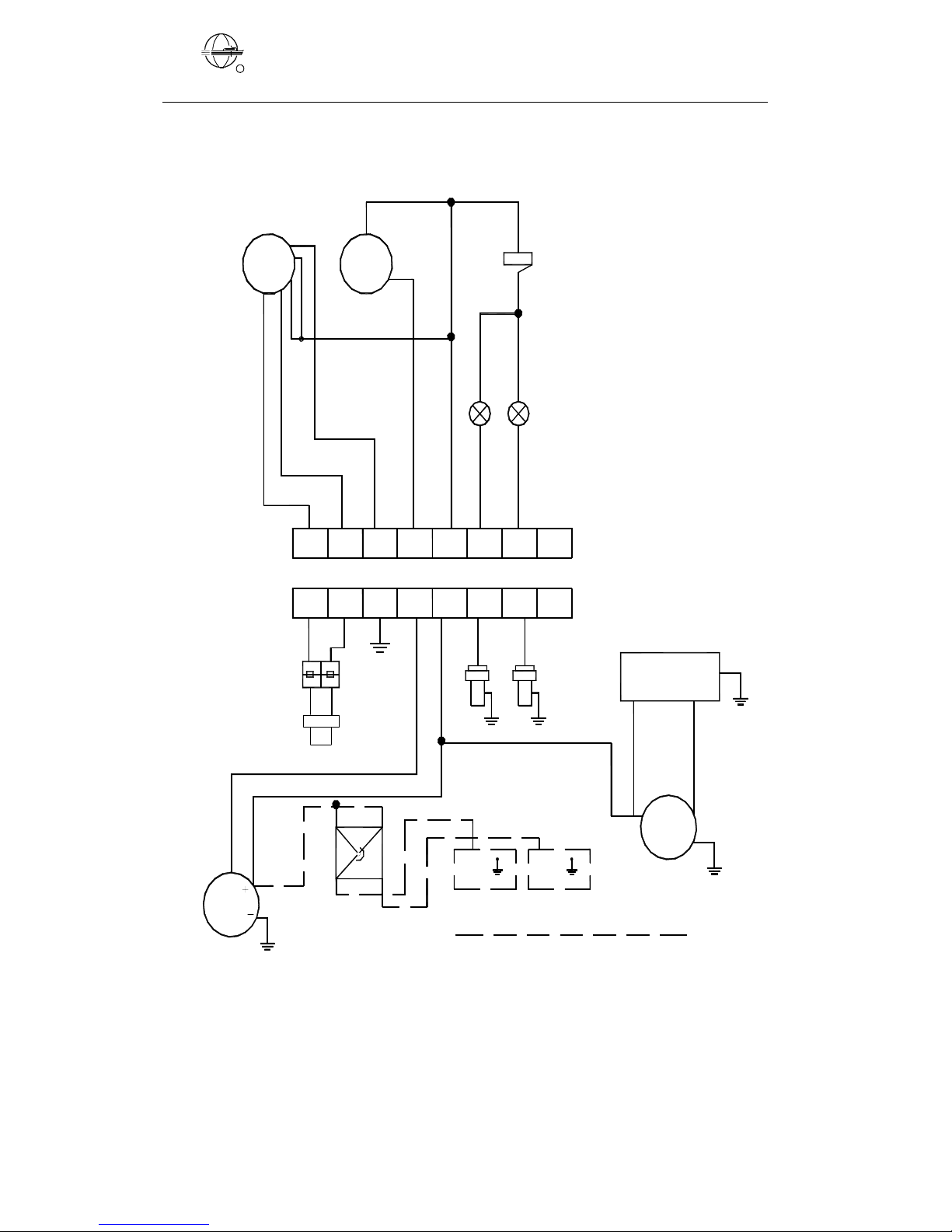
4.6 ELECTRICALDIAGRAM
Pressure sensor
Temp. sensor
Change over
Battery switch
Tachometer sensor
G
Starter
Generator
Items with dotted line not
included in normal delivery.
Battery 1
12 Volt
Battery 2
12 Volt
Double
charge diode
-+
50mm2
G+G
-
50mm2
B+
Armature
F
Magnetic
1
1
31
4
5
6
Tachometer
Low oil pressure alarm
High water temp. alarm
Voltage
regulator
65
342
234 65
1098711
97 81011
Discharge alarm
CAP
12
G
12
3
21
Switch
+Buzzer
Diode
Fig Electric diagram 1
EAST CHINA SHIPBUILDING INSTITUTE FACTORY
10
SIYANG
四洋
R
Pressure sensor
Temp. sensor
Change over
Battery switch
Tachometer sensor
G
Starter
Generator
Items with dotted line not
included in normal delivery.
Battery 1
12 Volt
Battery 2
12 Volt
-+
50mm2
G+G
-
50mm2
B+
Armature
F
Magnetic
1
1
31
4
5
6
Tachometer
Low oil pressure alarm
High water temp. alarm
Voltage
regulator
65
342
234 65
87
7 8
G
3
21
Switch
+Buzzer
Fig Electric diagram 2

EAST CHINA SHIPBUILDING INSTITUTE FACTORY
11
SIYANG
四洋
R
4.6.1 ELECTRIC SYSTEM PARTS DESCRIPTION
Following parts is installed either engine side or panel side
Item Electric diagram 1 Electric diagram 2
Tachometer ZS12109.Y0 ZS12109.Y0
Starting switch JK290 JK290
Buzzer FMQ-2715 FMQ-2715
Alarm lamp (watertemp.) AD11-16 AD11-16
Alarm lamp (lube pressure) AD11-16 AD11-16
Charge indicating lamp AD11-16 AD11-16
Tachometer sensor ZG912346 ZG912346
Temperature sensor WB9311 WB9311
Lube pressure sensor YB1011 YB1011
Starting motor QD138C QD138C
Battery voltage 12V 12V
Voltage regulator FT111 FT111
Generator JFW17H1 JFW17H1
Diode IN5408 (No fitted)
Capacity CB822 IUOJ400V (No fitted)
Charging diode 702R 702R
4.6.2 INSTRUMENTS PANEL
According the choice of the buyer, the engine set is normally fitted one
of the two instruments panel.
1. Tachometer 2. Alarm buzzer and lamp 3.Starting switch 4. Charging
lamp (no fitted in Electric diagram 2.)

EAST CHINA SHIPBUILDING INSTITUTE FACTORY
12
SIYANG
四洋
R
4.7 STARTINGPRECAUTIONS
Starting any engine can be dangerous in the hands of inexperienced
people. Before attempting to start any engine ,the operator should be fully
conversant with starting procedure and controls.
①.Ensure that the batteries are in serviceable condition and correctly
connected.
②.Check that the oil levels in the engine and the gearbox are correct.
③.Check that the fuel tank is full and that the system is primed.
④.Check that the all water drain plugs and cocks are closed. Check that
water inlet valves, if fitted, are opened.
⑤.Check that water level in the expansion tank is filled up with mixture
of water/antifreeze (40%).
4.8 CHECKS BEFORE STARTING
①.Oil level in oil sump and gearbox.
②.Coolant level in the expansion tanker.
③.Battery main switch is on .Oil pressure light and changing light will
now be on and the buzzer will sound.
5 OPERATION OFENGINE
5.1 STARTING
①Before attempting to start the engine ,the operator should be familiar
with the safety precautions as described earlier.
②Move the speed/gearbox lever into the neutral position by means of the
control lever.
③Turn the switch to energize the starting motor.
Release immediately, if the engine start ,and it will return to position
“0”.The alarm light as well as the buzzer should now be off.
④If the engine should fail to start ,due to poor battery condition ,turn the
battery switch to the second start battery and repeat the starting procedure.
⑤If the engine fail to start within 15 seconds ,despite good battery
condition ,release the switch and investigate the cause .The starting motor
should be allowed to cool for at least 15 seconds before attempting to
EAST CHINA SHIPBUILDING INSTITUTE FACTORY
13
SIYANG
四洋
R
restart.
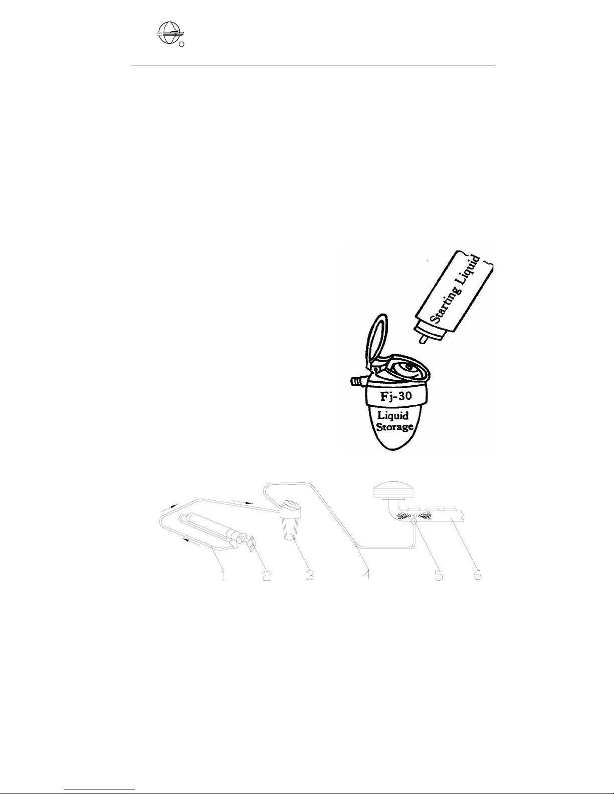
⑥At low temperature it may be necessary to ease the starting by means
of the start gas.
The operation method is shown as follows:
(1).Open the dust cover of the liquid storage. Insert the pouring liquid
pressure can into the hole of the liquid storage. Squeeze the can to pour
the liquid into liquid storage.
(2).Set the gearbox at idle
position and put the handle of
fuel rack at mid-position.
(3).Start the engine. At the
same time, operate the
hand-pump until the engine
runs stably.
(4).If knocking appears while
the engine is starting; the
operation of hand-pump must
be slowed or stopped, so as to
regulate the injecting liquid
quantity for starting the engine
stably.
CAUTION: Keep away from all heat sources (even sun
light).The liquid is highly flammable.
5.2 STARTING BY SPRING STARTER (IF INSTALLED)
1.Air pipe 2.Hand pump 3.Liquid 4.Liquid pipe 5.Injector 6.Air inlet pipe
low temp. starting liquid pouring system

EAST CHINA SHIPBUILDING INSTITUTE FACTORY
14
SIYANG
四洋
R
According to the buyer requests, we can install and supply the FQ
engine starter (hand starting) for the engine starting.
This starter makes use of man-power to press its spring to store the
energy. The engine is rotated, as the energy relives at a moments and causes
the engine running over the speed of starting revolution of the engine quickly,
and then the engine is starting.
Operation order and method:
1. Press the reset button.
2. Insert the handle, anticlockwise rotation, press the butterfly spring to
fully pressing state.(The red mark is appearing).
3. The energy will relieve at a moment when the lever is pressed. At
that time the engine speed rises over the starting revolution of the
engine, then the engine is starting.
Note: The step-lever must be situated in unabated pressure state
when the engine makes use of the FQ type starter.
4. If it is necessary to rotate the engine with the hands, press the reset
button and draw-up the reliever lever and then the engine can be
rotated with the handle.
Fig. Spring starting motor
287.6
release handle
116
DIR
130
DIR
reset button
cranking bar
125.75
37.75
75
78
APPROX
Note: 1. When use the FQ starter, never open the decompression.

EAST CHINA SHIPBUILDING INSTITUTE FACTORY
15
SIYANG
四洋
R
5.3 OPERATION
If one or more alarm do not go out, or light up when the engine runs,
the engine should be stopped at once to trace the reason.
When all function are normal, engage the gearbox by pushing the
control lever forward or backward.
Increase the speed gradually if possible, allowing the engine to warm
up, before going full speed.
In case of emergency, the lever can be moved into full speed position
immediately.
5.4 STOPPING
Move control lever into neutral position.
Allow the engine to idle for appr.2 minutes to cool.
Stop the engine.
Switch off the battery main Switch.
If fresh water is only used, all of cooling water must be drained out from
the cooling system when the ambient temperature is below 5℃(except anti-
freeze coolant is used)
6 .ROUTINE MAINTENANCE
The engine has passed the lifeboat engine test programmer before
delivery. Still however the engine is not completely run in.
It is recommended to operate the engine moderately during the first
hours after it has been put into service. Full speed only for short periods
during the first 15-20 hours.
6.1 INITIALATTENTION
1.Check and tighten all hose clamps and unions, paying particular
attention to the fuel system.
2.Check and tighten all external nuts and bolts, particularly mounting
bolts, shaft coupling bolts and exhaust manifold bolts and nuts.
3. Check belt tension, see ALTERNATOR BELT TENSION section.
4.Check lubrication oil and water coolant level .

EAST CHINA SHIPBUILDING INSTITUTE FACTORY
16
SIYANG
四洋
R
6.2 ROUTINE MAINTENANCE PERIODES
Period Attention
After the first 15 hours or after the
first 3months See INITIAL ATTENTION
Before start or weekly
Check engine oil level.
Check coolant level.
Check fuel level in tank.
Grease stern gland
Every 3 months or 25 hours Check gearbox oil level
Check battery condition
Every year or 200hours
Change gearbox oil and lube oil
Change lube oil filter
Check alternator belt tension
Check electric connect
6.3 LUBRICATION OILSPECIFICATION
Temperature in starting ℃Mono-grade Multi-grade
Below -15 5w 5w /30
Between and -15
4 10w 10w/30
Between and 4
30 20/20 w 15w/30
10w/30
Above 30 30
15w/40
20w/40
The temperatures mentioned in the table are the ambient temperatures
at the time when the engine is started.
However, if the running temperatures are much higher than the starting
temperatures a compromise must be struck and a higher viscosity oil used ,
providing starting is satisfactory. Multi grade oils overcome the problem,
provided they have a suitable specification .
The engines must be run on heavy duty lubricating oils, meeting the
requirements of API CC.DEF2101D, MIL-L-2104B or MILL-L-46152A/B

EAST CHINA SHIPBUILDING INSTITUTE FACTORY
17
SIYANG
四洋
R
Straight mineral oils are not suitable, neither are oils of less detergency than
specified.
API CD, Series 3, or MIL-L-2104C/D oils can inhibit the running in
process in new or reconditioned engine but can be recommended for
engines running at high load factor, particularly in conjunction with high
ambient temperatures.
Following or equivalent types of oil can be used:
Mobile Delvac 1300 series
Shell Rimula ×oil
Esso lube XD3+
Chevon Delco Super 3
Fina Solna 3
Norol Marine TMA 300
BP energol DS3
Gulfpride Seies 3
Elf Disal HD3
Texaco URSA S3
Castrol Deusol RX super
Amocol New Supper ACE3
6.4 GEARBOX OILSPECIFICATION
Automatic Transmission Fluid -ATF
FORD Specification M 2 C-33 G
GM Specification ATF DEXRON ⅡD
EXXON ATFD or ATF
(or refer to gearbox manual )
6.5 MAIN SPANNER TORQUE SETTINGS
DESCRIPTION N•M
Flywheel bolt 60
Cylinder head nut 140
Connecting rod bolts 70
Prop. shaft coupling bolts (acid proof) 70
Crankshaft main bearing 125
Table of contents
Other Siyang Engine manuals

Popular Engine manuals by other brands


Leadshine
Leadshine iSV2-RS Series user manual

MTU
MTU 12V4000M93 series operating instructions

MTU
MTU C13 operating instructions

Northern Lights
Northern Lights M80A13S Operator's manual

Detroit Diesel
Detroit Diesel MBE 4000 Service information

Briggs & Stratton
Briggs & Stratton 130200 Series Operating and maintenance instructions