Wahlberg Roll Down User manual

WWW.WAHLBERG.DK JENS JUULS VEJ 1
TELEPHONE: +45 86 18 14 20 8260 VIBY
Roll Down
Item No 249
User Manual

249.805.013 2 Date: 2021-12-09
Safety Information
WARNING! Read this manual before installing, powering or servicing the product; follow the
safety precautions listed below and observe all warnings in this manual and printed on the
product. If you have questions about how to operate the product, please contact you Wahlberg
Motion Design supplier or Wahlberg Motion Design.
The following symbols identify important safety information on the product and in this manual.
DANGER!
Safety hazard
WARNING!
Moving parts
can crush and
cut
DANGER!
Risk of
electric shock
WARNING!
Risk of fire
WARNING!
Hot surface
WARNING!
See manual
GENERAL PRECAUTIONS
−This product is for professional use and presents risks for sever injury or death.
−Always warm-up electronic equipment to room temperature before applying power.
−Isolate the product from power immediately if defective or showing signs of overload. Do
not reapply power until repairs have been completed.
−Do not modify the product in any way not described in this manual.
−Refer any service operation not described in this manual to a qualified technician.
−Install only genuine Wahlberg Motion Design parts.
PROTECTION FROM INJURY
−Fasten the product securely to a fixed surface, rig, or structure as described in this manual.
−Ensure that any supporting hardware can hold at least 10 times the weight of all the
devices they support.
−Block access below the work area whenever installing or servicing the product.
−Do not use the product to lift people or animals and do not exceed the load limits.
−Do not use the product over the head of people.
−When the product is installed and may not be used for some time, inspections and
maintenance according to this manual shall always be followed.
PROTECTION FROM ELECTRIC SHOCK
−Do not expose the product to rain or moisture.
−Use an AC power source with overload and ground(earth)-fault protection.
−Disconnect from AC power before servicing.
PROTECTION FROM BURNS AND FIRE
−Do not operate the product if the ambient temperature (Ta) exceeds 40° C (104° F).
−The exterior of the product becomes warm during use. Avoid contact by persons and
materials. Allow the product to cool for at least 10 minutes before handling.
DISPOSING OF THIS PRODUCT
Wahlberg Motion Design products are supplied in compliance with Directive 2012/19/EU of the
European Parliament and of the Council of the European Union on WEEE (Waste Electrical and
Electronic Equipment), including amendments where applicable. Help preserve the environment!
Ensure that this product is recycled at the end of its life. Your supplier can give details of local
arrangements for the disposal.

249.805.013 3 Date: 2021-12-09
Index
SAFETY INFORMATION 2
INDEX 3
TECHNICAL SPECIFICATIONS 4
DRAWING 5
INTRODUCTION 6
PACKAGE CONTENT ...................................................................................................................................... 6
DESCRIPTION............................................................................................................................................... 6
SAFETY FUNCTIONS ...................................................................................................................................... 7
AREA OF USE............................................................................................................................................... 7
USING FOR THE FIRST TIME ............................................................................................................................ 7
TRANSPORT ................................................................................................................................................ 8
PHYSICAL INSTALLATION 9
FASTENING THE PRODUCT TO A FLAT SURFACE................................................................................................... 9
MOUNTING THE PRODUCT ON A TRUSS............................................................................................................ 9
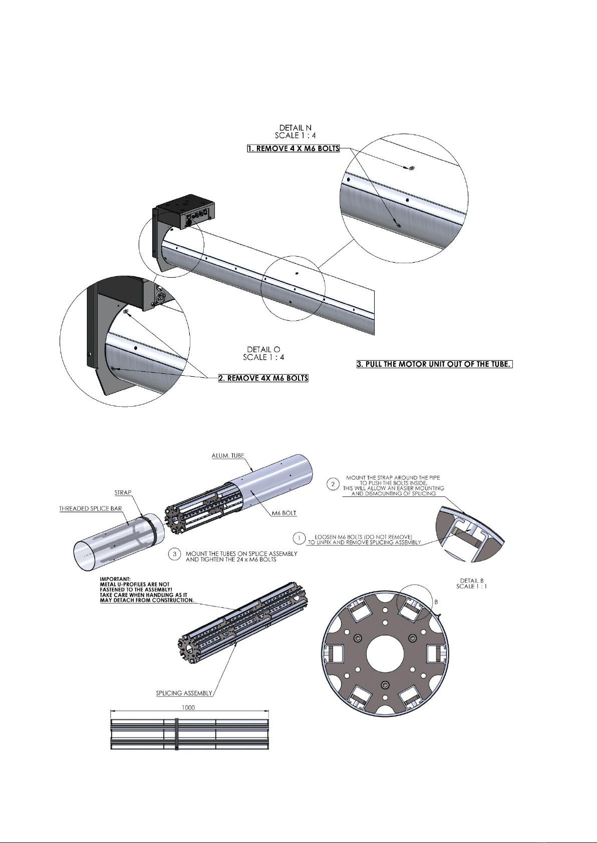
MOUNTING THE TUBE................................................................................................................................. 10
AC POWER 14
POWER CABLES AND POWER PLUG ................................................................................................................ 14
INSTALLING A POWER INPUT OR OUTPUT CONNECTOR ON A POWER CABLE........................................................... 14
DATA LINK 16
TIPS FOR RELIABLE DATA TRANSMISSION ........................................................................................................ 16
CONNECTING THE DATA LINK........................................................................................................................ 16
EMERGENCY STOP SWITCH (OPTIONAL) 17
ENABLE EMERGENCY STOP .......................................................................................................................... 18
READY TO USE ........................................................................................................................................... 18
SETUP 19
MENU SETTING.......................................................................................................................................... 19
MENU STRUCTURE ..................................................................................................................................... 20
ADJUSTABLE PARAMETERS........................................................................................................................... 22
DETAILED EXPLANATION OF PARAMETERS....................................................................................................... 23
DMX ADDRESS SETTING ........................................................................................................................... 25
ADJUSTING HARD LIMIT SWITCHES ................................................................................................................ 26
NORMAL OPERATION ................................................................................................................................. 28
SYNCHRONIZED MOVEMENTS OF MULTIPLE ROLL DOWNS................................................................................. 29
LED FUNCTIONS........................................................................................................................................ 30
ERROR AND ERROR CODES:.......................................................................................................................... 30
SERVICE AND MAINTENANCE 33
PARTS...................................................................................................................................................... 33
ON-SITE SERVICE........................................................................................................................................ 33
MAINTENANCE PLAN .................................................................................................................................. 34
CHECKLIST ................................................................................................................................................ 34
POWERCON TRUE1......................................................................................ERROR!BOOKMARK NOT DEFINED.
APPENDIX 1 - DIMENSIONS 35
APPENDIX 2 - POWERCON 37
APPENDIX 3 –BLOCK SCHEMATIC 39
ROLL DOWN - CHEAT SHEET 40

249.805.013 4 Date: 2021-12-09
Technical specifications
Model: Roll Down
Item no.: 249
Dimensions (L×W×H):
Motor clamp 190 × 320 × 368 mm (7.5 × 12.6 × 14.5 in)
Tube Ø200 × 1500-12000 mm (Ø7.9 × 59.1-472.4 in)
Power supply: 208-240V/AC 50-60 Hz
Power consumption: 550 W (2,7-2,3A)
Power inlet: Neutrik powerCON TRUE1 NAC3PX-TOP (F/M)
DMX control signal: DMX 512 1990 + DMX512A / 6 channels used
DMX connection: 5 pole XLR (F/M)
Lifting height: 18 m (59.1 ft)
Lifting capacity: 35 kg (77.2 lb)
Lifting speed: Variable, 5-183cm/s (2-72 in/s)
Minimum load: None
Noise emission: ~70 dB
Ambient temperature: 5-40°C (32-104°F)
Own weight:
Motor clamp 40 kg (88.2 lb)
Tube 5,1 kg/m (3.43 lb/ft)
Mounting clamp: 4× Slim eye coupler 42-52 mm (2 in)
Motor: 230V AC, 0.55 kW
Duty cycle: Maximum 30% when running more than 10min.

249.805.013 6 Date: 2021-12-09
Introduction
Thank you for selecting the Roll Down, a DMX controlled Roll Down from Wahlberg Motion Design.
Before using the product for the first time, please read this manual carefully. Failure in handling
can cause injury of persons and/or damage the product.
Package content
1× Roll Down
1× PowerCON NAC3FX-W-TOP female plug for power cable
1× User manual
1× Cheat sheet
Description
Roll Down is a Roll Down for stage use, mainly for use in theatres, shows and concerts.
It lifts fabrics in and out of the stage sphere at a maximum load of 35 kg up and down. The lifting
height is 18 m and the lifting speed is between 5 cm/s and 183 cm/s.
The Roll Down is controlled by the standard DMX signal, so a usual lighting desk can be used to
control the movement, programmed as any light.
For a limited number of Roll Downs, a standard lighting desk can be used, but when many Roll
Downs are used, more advanced desks should be used to maintain easy control of the units.
The Roll Down uses 6 channels of the DMX-line, and they control the position, speed, limits, and
reset functions.
The Roll Down has an advanced internal positioning system with 16 Bit, used for finding the
position desired by the operator. With a 16 bit positioning channel (channel 1 MSB and channel 2
LSB) the operator can set the desired position, and the Roll Down will run to this position, at the
maximum speed (channel 3).
Channel 4 is used as a safety channel. The motor will not run using DMX if channel 4 is not enabled.
With channel 5 and 6 it is possible to set the soft TOP and BOTTOM limits of the movement.
Channel 5 is also used for resetting the Roll Down, when powering up if the position was not saved
when shut down.
On the Roll Down it is also possible to adjust the hard TOP and BOTTOM limits and, in that way,
set the absolute span of motion regardless of any DMX control.
Multiple Roll Downs are easily daisy chained with power in-out and DMX in-out, allowing to create
advanced and dynamic movements with several Roll Downs working together in the same
installation.

249.805.013 7 Date: 2021-12-09
Safety functions
The control system ensures that the motor only is powered when:
•The DMX signal is reliable.
•The mode, position and speed control are set correctly.
•The tube position is within the span of the soft and hard limits.
•No overload.
The Roll Down should only be operated by an experienced DMX-controlled-lighting-desk-operator.
The lighting desk must be programmed according to the manual, so the Roll Down will stop when
the speed is put to 0 %. It is also possible for the user to stop the Roll Down by disconnecting it
from the mains power. After power failure the start position of the Roll Down may need to be
adjusted before the Roll Down can function properly again.
Manual operation of the Roll Down is only intended for installation, service, and tests.
Area of use
WARNING! To reduce the risk of electric shock or injury use indoors only.
WARNING! To reduce the risk of electric shock, do not expose to rain.
The Roll Down is intended for indoor use only. It is designed for lifting and lowering material at
the weight and speed stated in "Technical specifications" on page 4. Any other use of the product
may result in a risk of injury of persons or equipment damage.
Exceeding the load rating may cause failure of the equipment.
Use only the Wahlberg Motion Design approved mounting connectors to secure the load to the
tube. Failure to mount the load securely can result in a risk of injury of persons or equipment
damage.
Do not modify the product. For any modification contact Wahlberg Motion Design.
It is the customer's sole responsibility to comply with any relevant local laws, regulatory
requirements, and restrictions, concerning the use of the product.
Using for the first time
IMPORTANT! The Roll Down must be protected from environmental factors such as physical
shocks and vibration during transportation and storage.
WARNING! Read “Safety Information” on page 2 before installing, powering, operating, or
servicing the Roll Down. Before applying power to the product.
−Check the Wahlberg Motion Design website at www.wahlberg.dk for the most recent
documentation and technical information about the product. Wahlberg Motion Design user
manual revisions are identified by the revision number in the bottom of each page.
−Carefully review the “Safety Instructions” on page 2.
−Check that the local AC mains power source is within the power voltage and frequency ranges.
−See “Power cables and power plug” on page 14. Install the provided Neutrik powerCON TRUE1
NAC3FX-W-TOP power connector on a suitable power cable. If using the power from a mains
power outlet, install a suitable power plug on the power cable.

249.805.013 8 Date: 2021-12-09
Transport
IMPORTANT! The Roll Down must be protected from environmental factors such as physical
shocks and vibration during transportation.
Before transport, it is important to roll the fabric of the Roll Down up until the hard TOP limit, and
then wrap the remaining fabric around the tube. Fix the fabric with a cable tie or an elastic cord.
Use only the original packaging or flight case for protecting the product during transport. Contact
Wahlberg Motion Design for enquiries regarding flight cases or pallet frames.

249.805.013 9 Date: 2021-12-09
Physical installation
WARNING! The Roll Down must be either fastened to a flat surface such as a roof or clamped to
a truss or similar structure in such a way that the mounting clamp points upwards. Do not apply
power to the product if it is not securely fastened.
WARNING! The supporting surface must be hard and flat. Fasten the product securely.
WARNING! Use only the supplied rigging clamps.
Fastening the product to a flat surface
The Roll Down can be fastened to flat surface such as a roof. Check that the surface can support
at least 10 times the weight of all products and equipment to be installed on it.
Mounting the product on a truss
The Roll Down can be clamped to a truss or similar rigging structure.
To clamp a product to a truss:
1. Check that the rigging clamps are undamaged and that the rigging structure can support at
least 10 times the combined weight of all products and equipment to be installed on it.
2. Block access under the work area. Working from a stable platform, hang the product on the
truss with the mounting clamp upwards. Tighten the rigging clamp.
3. Use the supplied 2 slim couplers sitting on the top plate. It is important to use both slim
couplers for mounting because the load is not evenly distributed across the product.
4. Install a suitable safety cables when the product is hanging over-head and verify that it
complies with either EN 60598-2-17:2018 section 17.7.4 or BGV C1/DGUV 17.
Safety Cable

249.805.013 10 Date: 2021-12-09
Mounting the tube
The Roll Down comes with either a single tube, or two tubes with a splice that allows a total length
of the tube up to 12 meters.
Single tube:
Using a splice:

249.805.013 11 Date: 2021-12-09
Mounting the fabric
WARNING! The fabric must be mounted on the tube in a way to ensure that the fabric never can
damage the Roll Down.
WARNING! There should be minimum 1½ round left on the tube when the fabric is rolled all the
way out if it is mounted with the rail.
WARNING! There should be minimum 2 round left on the tube when the fabric is rolled all the
way out if it is mounted with tape.
Mount the fabric in the right position
When mounting the fabric, it is important to move the tube to the desired bottom position before
you start.
Example: If you are mounting a fabric with a length of 4 meters, follow these steps.
1. Set all channels to 0% and enable the motor by setting channel 4 (50-55%).
2. Move the tube to the hard TOP limit with channel 5 (until it stops).
3. Calculate the number of rotations needed for the specific fabric using the formula below.
4. Move the tube down with channel 6 while counting the number of rotations calculated
above.
(2)
(4)
5. Mount the fabric on the tube either with the rail or with tape, see instructions on the next
page for details.
6. Now return to the desired soft TOP position using channel 5.
(5)
(7)
Soft TOP Limit
OR
Until STOP
# of rotations calculated
Add fabric

249.805.013 12 Date: 2021-12-09
7. Then set the range/soft BOTTOM limit for the desired movement with channel 6.
CAUTION! For this specific situation, the range shall be less than 4 meters to ensure 1½
or 2 rounds of fabric is remaining on the tube.
8. Now the 100% position will be with the fabric rolled all the way up and the 0% position
will be with the fabric rolled all the way out.
(8)
(10)
ATTENTION! Set channel 4 to 0% to power-up again without the needing to readjust the
soft TOP limit.
ATTENTION! If you do not move the tube down before mounting the fabric the hard TOP
limit will prevent you from rolling the curtain all the way up.
If required, the hard TOP and BOTTOM limit can be offset in steps of quarter turns of the
tube, and this simply done by removing the four screws near the control unit and carefully
turn the black tube ending as shown below.
Soft BOTTOM Limit
Positioning
100%
0%
Remove 4x M6 bolts and
reapply immediately
whenever adjusted.
Seen from the back
side of the control unit
Moving the black end part this
way will move the hard limit
offset up.
Example: In situations when the
fabric is not entirely rolled up
before it is stopped by the hard
TOP limit.
Moving the black end part
this way will move the hard
limit offset down.
Example: In situation when
the fabric is not entirely
rolled out before it is stopped
by the hard BOTTOM limit

249.805.013 13 Date: 2021-12-09
Using the mounting rail
The Roll Down has a rail that can be used for mounting the fabric along the entire length of the
tube.
The fabric is mounted by loosening the Hex screws holding the rail in place. When they are all
loose, place the fabric under the rail and tighten the screws again to hold it in place.
Make sure the fabric is mounted on the correct side of the rail. If it is mounted on the wrong side,
it will fold over itself when moving to the TOP limit.
Refer to Appendix on page 35 for additional illustrations.
Using tape
The fabric can also be taped to the tube, using single- or double-faced tape. This allows the fabric
to be mounted at any angle. If tape is used for securing the fabric 2 rounds must remain on the
tube when it is fully rolled out.

249.805.013 14 Date: 2021-12-09
AC power
WARNING! Read “Safety Information” on page 2 before connecting the product to AC mains
power.
WARNING! For protection from electric shock, the product must be grounded (earthed). The
power distribution circuit must be equipped with a fuse or circuit breaker and ground-fault
(earth-fault) protection.
WARNING! Socket outlets or external power switches used to supply the product with power
must be located near the equipment and easily accessible so that the product can easily be
disconnected from power.
WARNING! Check that the voltage range specified on the serial number label matches the local
AC mains power voltage before applying power to the product. Do not apply AC mains power
to the product at any other voltage than that specified.
Power cables and power plug
The Roll Down requires a power input cable with a Neutrik powerCON TRUE1 NAC3FX-W(-TOP)
cable connector for AC mains power input. The cable must rated 20A minimum, have three
conductors 1,5mm2 (AWG 16) minimum conductor size and an outer cable diameter of 6-16mm
(0.24-0.47 inch). Cables must be heat resistant to 90°C (194°F) minimum. In the EU the cables must
be <HAR> approved or equivalent and in the USA minimum hard usage type SJT or equivalent.
If you install a power plug on the power cable, install a grounding-type (earthed) plug that is rated
20 A for USA and 16A for Europe. Follow the plug manufacturer’s instructions. Table 1 shows
standard wire color-coding schemes and some possible pin identification schemes; if pins are not
clearly identified, or if you have any doubts about proper installation, consult a qualified
electrician.
Table 1 - Colour guide
Wire Colour
Conductor
Symbol
Screw (US)
Brown
Live
L
Yellow or brass
Blue
Neutral
N
Silver
Yellow/green
Ground (earth)
or
Green
Installing a power input or output connector on a power cable
To install a Neutrik powerCON TRUE1 NAC3FX-W(-TOP)/NAC3MX-W(-TOP) input/output
connector on a power cable, follow the original Neutrik instructions in the Appendix on page 37.

249.805.013 15 Date: 2021-12-09
By supplying power to the Roll Down, the display will show a start-up screen sequence showing
the model number
Followed by a screen showing the software version, e.g. SW 503.003.012 as shown below
Then a description of how to enter the menu
When it changes to the following, the Roll Down is ready to be operated:

249.805.013 16 Date: 2021-12-09
Data link
A DMX 512 data link is required in order to control the Roll Down via DMX. The Roll Down has 5-
pin XLR connectors for DMX data input and output. The pin-out on all connectors is pin 1 = shield,
pin 2 = (-), and pin 3 = (+).
Pins 4 and 5 in the 5-pin XLR connectors are not used in normal operation and are available for
possible additional data signals as required by the DMX512-A standard. However, if desired this
additional port may also be used to feedback the actual position of the tube, but in such case, it is
not suitable for daisy chaining.
The Roll Down is subject to the common limit of 32 devices per daisy-chained link. Note that if
independent control of a Roll Down is required, it must have its own DMX channels assigned.
Products that are required to behave identically can share the same DMX channels. To add more
products or groups of products when the above limit is reached, add a DMX universe and another
daisy-chained link.
Tips for reliable data transmission
Use shielded twisted-pair cable designed for RS-485 devices: standard microphone cable cannot
transmit control data reliably over long runs. AWG24 cable is suitable for runs up to 100 meters
(328 ft.).
Never split a DMX line without using an opto-isolated RS-485 splitter/amplifier.
Terminate the link by installing a termination plug in the output socket of the last Roll Down. The
termination plug, which is a male XLR plug with a 120 Ohm, 0.25W resistor soldered between pins
2 and 3, “soaks up” the control signal so it does not reflect and cause interference. If a splitter is
used, terminate each branch of the link.
Connecting the data link
To connect the Roll Down to data:
1. Connect the DMX data output from the DMX controller to the male 5-pin XLR DMX input
connector (DMX 512 IN).
2. Connect the DMX output of the products to the DMX input of another product and
continue connecting products output to input (DMX 512 OUT).
3. Terminate the last product on the link with a 120 Ohm resistor.
The DMX lamp is the green LED, above the display.
−Glows constantly, when the DMX connection is correct.
−Flashes if the DMX signal is missing or wrongly connected.

249.805.013 17 Date: 2021-12-09
Emergency stop switch (Optional)
WARNING! By default, the emergency stop is NOT enabled!
The Roll Down can be configured with an emergency stop; by default, the emergency stop is not
enabled.
The DMX control from a lighting desk should always have a set up so there is a button that sets
the speed of the Roll Down in operation to 0%. Normally lighting desks have a “blackout” button
that sets all intensity channels to 0% and this will also cause the Roll Down to stop when assigned
correctly.
If the emergency stop switch is activated the red Error LED will be lit and the screen display shows:
‘EMERGENCY STOP PRESSED’ and the current start channel of the unit:
The emergency stop switch is connected to the male 4 pole XLR connector on the winch. Pin 1 and
Pin 4 should be powered with 12-15 volt DC to enable operation of the winch.
Pin out:
Connection
Pin 1
GND
Pin 2
Not connected
Pin 3
Not connected
Pin 4
12-15 V DV
The emergency stop power supply and plug is available for purchase from Wahlberg Motion
Design.

249.805.013 18 Date: 2021-12-09
Enable Emergency stop
In ‘MENU NAVIGATE’ change ‘E STOP’ from OFF
to ON
Refer to section ‘
Menu setting’on page 19 for guidance on how to navigate the menu.
Ready to use
When the emergency stop has been enabled, and the Roll Down is connected to power, DMX, and
an emergency stop switch, it is ready for use, and can be controlled from the lighting desk.

249.805.013 19 Date: 2021-12-09
Setup
WARNING! Read “Safety Information” on page 2 before installing, powering, operating, or
servicing the product.
WARNING! Only experienced DMX users should operate the product. Contact Wahlberg Motion
Design for further information and education on DMX protocol.
Menu setting
Use the buttons on the display to enter and change menu settings
Use the arrows & to go up or down in the menu
Press to set values.
Press to go back one level in the menu
Press and hold both the up and down arrow for 1 second to enter and leave the menu navigation
mode, see page 21 or continue using the control mode as explained on the next page.

249.805.013 20 Date: 2021-12-09
Menu structure
The menu structure is divided into two different areas for safer motor control. Control mode and
menu navigation mode. To change between the two push both buttons & and
hold them for 3 seconds.
Control mode
The display shows:
Shift to next screen by press.
The screen shows the tachometer value for the current position, wanted position, distance and
speed in motor RPM’s.
E.g. the motor is moving with 1750 RPM’s of speed from current position with tachometer value
10.000 and the wanted position has the tachometer value of 24.250:
Shift to next screen by press.
The screen shows the DMX channel values, if e.g. DMX channel 1 is set to 100% and DMX channel
3 is set to 100%, the screen will show:
To shift back to the previous screen by pressing.
P:
Current position (values 0-99.999)
W:
Wanted position (values 0-99.999)
D:
Distance from current to wanted position
S:
Speed (values from 0-maximum motor
RPM setting in operation)
DMX
channel
1
DMX
channel
2
DMX
channel
3
DMX
channel
4
DMX
channel
5
DMX
channel
6
DMX
channel
7 (not
used)
DMX
channel
8 (not
used)
This manual suits for next models
1
Table of contents
Other Wahlberg Engine manuals
Popular Engine manuals by other brands

Continental Refrigerator
Continental Refrigerator IO-240-A Installation and operation manual

Volvo
Volvo MD2010 Workshop manual

Komatsu Utility
Komatsu Utility 3D82AE Series Shop Manual

Ingersoll-Rand
Ingersoll-Rand MVA017B/VSM-5842 Operation and Maintenance Information

Mitsubishi
Mitsubishi 4G1 series General information

ESI
ESI M50Q 230VAC Series Quick setup