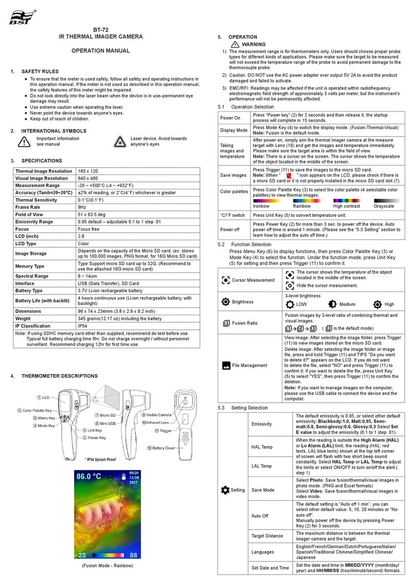
SKF TKTI 10 User manual

Instructions for use
SKF TKTI 10


2 SKF TKTI 10
EC Declaration of conformity ....................................................................................3
Safety recommendations ..........................................................................................4
1. Description .......................................................................................................5
2. Getting started .................................................................................................5
2.1 Contents.......................................................................................................................... 5
2.2 Charginginternalbattery............................................................................................. 6
3. Basic features of the SKF Thermal Camera TKTI 10 ..........................................7
3.1 Hardware........................................................................................................................ 7
3.2 SwitchingontheTKTI10............................................................................................. 8
3.3 Focusing.......................................................................................................................... 8
3.4 Usingthelaserpointer................................................................................................. 9
3.5 Fieldofview..................................................................................................................10
4. Using the direct access buttons .......................................................................10
4.1 Directaccessbutton1................................................................................................11
4.2 Directaccessbutton2................................................................................................13
4.3 Directaccessbutton3................................................................................................14
4.4 Directaccessbutton4...............................................................................................14
4.4.1MenuInfraredSettings...................................................................................15
4.4.2MenuMeasurementOptions...........................................................................17
4.4.3MenuCameraSettings.....................................................................................20
4.4.4MenuAudioSettings........................................................................................21
4.4.5MenuImageBrower.........................................................................................22
4.4.6MenuDate&TimeSettings............................................................................22
4.4.7MenuLanguageSelection...............................................................................23
5. Saving and annotating pictures.......................................................................24
5.1 Savingapicture...........................................................................................................24
5.2 Addingavoicemessage.............................................................................................24
5.3 AddingaCaption.........................................................................................................25
6. Technical specications ...................................................................................27
Table of contents

3SKF TKTI 10
EC Declaration of conformity
We,SKFMaintenanceProducts,Kelvinbaan16,
3439MTNieuwegein,declarethat
SKF Thermal Camera
TKTI 10
Conformstothefollowingstandards;
• EMCDirective89/336/EECasamended
“CouncilDirectiveontheapproximationofthelawsoftheMemberStates
relatingtoelectromagneticcompatibility”asoutlinedinharmonizednorms:
EN61000-6-2:2005Immunityforindustrialenvironments
EN61000-6-3:2007Emissionstandardforresidential,commercialand
light-industrialenvironments
• FederalCommunicationsCommissionregulationCFR47:2007subpart15b
Thelaserisclassiedinaccordancetothe
21CFR1040.10and1040.11exceptfordeviationspursuanttolasernotice
No.50datedJuly26th2001
andcomplieswithIEC/EN60825-1(2001).
TheNetherlands,January2009
SébastienDavid
ManagerProductDevelopmentandQuality

4 SKF TKTI 10
Safety recommendations
Warning
• TheequipmentdescribedinthisdocumentusesaClass2laser.
Donotlookdirectlyintothelaserbeamorthelaserbeamexitaperture,
irreversibledamagetotheeyemayoccur.Thelasershouldnotbe
operatedwhentherearepersonnelinthecamera’seldofview.
Caution
• Useofcontrolsoradjustmentsorperformanceofproceduresotherthan
thosespeciedinthisdocumentmayresultinhazardouslaserradiation
exposure.
• Tohelpminimizeburnhazards,beawarethatthermalimagesofhighly
reectiveobjectswillshowlowerthanactualtemperaturemeasurements.
• Donotuseinamannernotspeciedinthisinstructionforuse.
• Donotuseinexplosiveatmospheres.
• Alwaysusethelanyardprovidedtohelpminimisedamagetothethermal
imagerandpersonalinjuryaccidents.
• OnlyusegenuineSKFsparesandaccessories.Othersparesand
accessoriesmaydamagethethermalcamera.
• Thethermalcameracontainsnouserserviceableparts.Openingthe
imagercasingvoidswarranty.Allserviceworkmustbecarriedoutbyan
authorisedSKFworkshop.

5SKF TKTI 10
1. Description
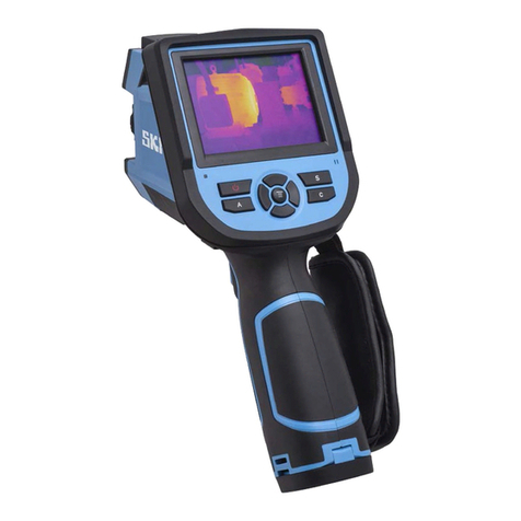
TheSKFTKTI10isadigitalcamerawithadvancedthermalimagingcapabilities.
ItisidealforuseasaPredictiveMaintenance(PdM)tool.Thermographyisanon-invasive
techniqueandiswellsuitedformechanicalandelectricalinspections,energyconservation
andplantsafetyactivities.TheTKTI10hasalargebacklit31/2”colourscreen,which
givesaclear,sharpresolutionusinganyoftheeightcolourpalettes.Designedforeasy
operation,multipletemperaturescanbemeasuredandthedifferencesbetweenthem
displayed.Otheradvancedmeasurementoptionsarealsoavailable.Imagescanbestored
asradiometricdataanddigitalimagesonthemicroSDcard(supplied).PowerfulPC
softwaresuppliedwiththeTKTI10,allowstheimagestobefurtheranalysedandtobe
optimisedforeaseofinterpretation.
2. Getting started
2.1 Contents
4
2
1
3
2
5
Figure 1. Contents of the case
1. SKFThermalCameraTKTI10
2. Powersupplyunit(12V)andInternationaladaptors
3. CD-Softwareandinstructions(MP5358)
4. USBcable(cameratoPC)
5. Detachablehandle
andQuickStartguideSKFThermalCameraTKTI10(MP5361)
Inspectalltheitems.Ifanyitemisdamagedormissing,pleasenotifyyourdealerorlocal
SKFofceimmediately.

6 SKF TKTI 10
2.2 Charging internal battery
• TheTKTI10’sbatterycanbechargedinthecamerabyconnectingthesupplied12V
powersupplyunitintotheDCsocketinthehatchofthethermalcamera(seegure2;
connectionports).
• Thebatteryconditionindicatorappearsonthescreenwhentheimagerisswitchedon
(seegure3).
• Theredledindicatesthatthecameraischarging.Thegreenledmeansthatthe
cameraisfullycharged(seegure2).
• TherechargeablebatterywillpowertheTKTI10forapproximately6hours.
red/green charging indicator
Figure 2. Connection ports
Temperature
Span
Level
Spot Emissivity Reected Battery
temperature temperature condition
StatusofDirectaccessbuttons
Theyellowborderediconistheactivefunction.
Figure 3. Screen overview

7SKF TKTI 10
3. Basic features of the SKF Thermal Camera TKTI 10
3.1 Hardware
TheTKTI10isdesignedforuseasahandheldthermalcamera.Youcanusethe
detachablehandleifconvenient.ThermalimagesarestoredonamicroSDmemorycard
(suppliedsizeis1GB).TheseimagescanbetransferredtoaPCusingtheUSBcable
provided.PCsoftwareisincludedforviewingandanalysisofsavedthermalanddigital
images.
Hatch
On/offbutton
4navigation
buttons&
Centretoggle
button
Screen
Directaccessbuttons1to4
Figure 4. Main camera controls
Laserbutton
Focusring
Exposure
button
Light
Digital
cameralens
Thermal
cameralens
Connectionports:
-12Vcharger
-USB
-MicroSD
-Headset
Detachable
handle
Exposure
button
Screw
Figure 5. Front panel
Speaker
Microphone

8 SKF TKTI 10
3.2 Switching on the TKTI 10
• TheTKTI10isswitchedonandoff
bypressingandholdingdownthe
powerbutton.
• TheTKTI10takesapproximately
tensecondstobecome
operational.
Figure 6. Camera on/off button
3.3 Focusing
Sharpentheimagebyrotatingthe
focusring
Figure 7. Focusing
Ifthecameraisnotfocused,thethermalimagequalitywillbepoorandtemperature
measurementswillnotbeaccurate.Tofocusmakecertainthatthedisplayblendingisless
than100%visible(seechapter4.2).
Rotatingthefocusringinaclockwisedirection(fromuserpointofview)focusesthe
imagesatshorterdistancesdowntoaminimumof30cm.
Rotatingthelensintheoppositedirectionfocusestheimageratlongerdistancesupto
innity.
Rotatethelensuntiltheimagehasasharpdenition,withthesharpestcontrastatobject
edges.
Focused Not focused
Figure 8. Focusing

9SKF TKTI 10
Whenfocusing,afocusbarappearsonthescreenshowingthefocuseddistance.
Figure 9. Focus bar
3.4 Using the laser pointer
WhentheTKTI10isswitched‘ON’,thelasermaybeactivatedbypressingandholding
downthelaserbuttononthefrontoftheimager(seegure5)orthelaserpointerbutton
onthehandle.
Laserpointerbutton
Figure 10. Laser pointer button
Thelaserpointerisusedtoilluminateandidentifyfeaturesintheimage.
Note:Thelasercentreisalignedtoobjectsatadistanceof3m.

10 SKF TKTI 10
3.5 Field of view
Figure 11. Field of view
TheTKTI10hasa20˚x20˚eldofview,anda47x47pixeldetector.
Thedetectorresolutioncanbeinterpolatedto180x180(seesection4.4.1;Interpolation).
4. Using the direct access buttons
TheDirectaccessbuttonpositionsareshowninthebelowgure.Theiconwithayellow
bordershowtheselectedfunctionthatcanbeadjusted(seealsogure3):
5
4
3
2
1
6
6
6
6
1. Directaccessbutton1
2. Directaccessbutton2
3. Directaccessbutton3
4. Directaccessbutton4
5. Centretogglebutton
6. 4Navigationbuttons
Figure 12. Direct access buttons
47
47 20˚ 20˚

11SKF TKTI 10
4.1 Direct access button 1
WithDirectaccessbutton1youcanaccess:
a. Alignment
b. Severalmeasurementoptions,ifenabledintheMeasurementOptionmenu.
a. Alignment (ifvisibleon :seeDirectaccessbutton2).
Asthevisibleandthermalcameraarenotco-incidentthevisibleandthermalimageoften
needtobealigned.Thisisusuallyrequiredwheninspectingobjectsatdifferentdistances.
Itispossibletoalignthethermalandvisible(digital)imagesonlyon“Live”mode.
Furtheradjustmentscanbedoneonthesavedimageswiththesoftware.
1. PressDirectaccessbutton2tolocatethecameraon/off
optionandtogglethecentrebuttontoturnthecamera
optionon.
2. PressDirectaccesbutton1tolocatethealignment
option.
3. Alignmentpresetsareaccessiblewithcentretoggle
button.Youcanalsousethenavigationbuttonsfornal
adjustment.
Press left navigation arrow fully aligned Press right navigation arrow
Note: Only the digital image is moving.
Figure 13. Examples of alignment

12 SKF TKTI 10
b. Measurement options
TobedisplayedwhilenavigatingwithDirectaccessbutton1,theseoptionsneedtobe
enabledintheMeasurementOptionmenu.
ToaccesstheMeasurementOptionmenu
pressDirectaccessbutton4
andselectthecorrecticon:
Directaccessbutton1candisplaythefollowingicons:
Cursorone
Menu>Measurement
options>Cursors:1
Cursortwo
Menu>Measurement
Options>Cursors:2
Isothermlowtemp
Menu>Measurement
Options>Isotherms:(Low,
High&Low)
Isothermhightemp
Menu>Measurement
Options>Isotherms:(High,
High&Low)
Area
Menu>Measurement
Options>Area:On
Hot/coldtracking
Menu>Measurement
Options>Tracking:(High,
Low,High&Low)
Lowtemprange
Menu>Measurement
Options>Temp.Alarm:(Low,
High&Low)
Hightemprange
Menu>Measurement
Options>Temp.Alarm:
(High,High&Low)
Horizontalprole
Menu>Measurement
Options>Temp.Prole:
Horizontal
Verticalprole
Menu>Measurement
Options>Temp.Prole:
Vertical
Align
(IfCameraOn :
seeDirectAccessButton2)
Seefordetaileddescriptionofthefunctionalityoftheseoptionssection4.4.2:
MeasurementOptions.

13SKF TKTI 10
4.2 Direct access button 2
Whenapictureisdisplayedonthescreen,thisbuttongivesaccesto3differentoptions
with2settingsforeach(toggleusingcentretogglebutton):
1. Camera on/off
Enable/disablethedisplayofadigitalpictureblendedwiththermal
image.
Howtosetblending:
1. PressDirectaccessbutton2tolocatethecameraon/offoptionand
togglethecentrebuttontoturnthecameraoptionon.
2. Blendbetweenthedigitalandthermalimagebypressingthe
up/down,left/rightarrowbuttons.
3. Thiswillblendthetwoimagesonapercentagescale0%,25%,50%
75%and100%.
a) 100% Thermal only b) 100% Digital only c) 50% Thermal/50% Digital
2. Light on/off
Enable/disablehighpowerLEDinthefrontpanel,helpfultotake
picturesinadarkenvironment(seegure5).
3. Auto/manual temperature range scale
Auto
Automaticallyadjuststheimagetoallowforthehighestandlowest
temperatureinthescene.Usefulwhenstartinganimagerand
switchingtodifferentpartsofascene.
Manual
Theuserdenestherangeoftemperaturestobedisplayed.
Manualsettingisusefulwhentheuserwantstoexaminevarious
piecesofsimilarequipment.Inaxedtemperaturerange,anomalies
ordiscrepanciescanbehighlightedvisuallyveryeasily.
Setthespanusingtherightandleftnavigationbuttonandthelevel
usingtheupanddownnavigationbutton.
4. Play audio (only in picture viewing mode)
Playspreviouslyrecordedvoiceannotationsavedwiththeimage.

14 SKF TKTI 10
4.3 Direct access button 3
Thisbuttontogglesbetweenliveimageandafrozenimage
live frozen
4.4 Direct access button 4
Thisbuttonselectsthecameramenus.
Infrared
Settings
Measurement
Options
Camera
Settings
Audio
Settings
Image
Browser
Date & Time
Settings
language
Selection
Menu selection
1. PressDirectaccessbutton4toenterthemenuselection
screen
2. Navigatetothedesiredoptionusingthenavigationbuttons.
(Theiconwiththeyellowbordershowtheselectedoption)
3. PressDirectaccessbutton3orthecentretogglebuttonto
entertheselectedoption.
Menu items
1. Arrowupanddowntothedesireditem
2. Usetheleft/rightarrowstochangethevalueofthisitem
3. SelectDirectaccessbutton4toexitor
Directaccessbutton1togobacktothemainmenu.

15SKF TKTI 10
4.4.1 Menu Infrared Settings
Infrared
Settings
• Emissivity
Differentsurfacescanradiatedifferentamountsofinfraredenergyatthe
sametemperature.Thisdifferenceintemperaturemeasurementcanbe
correctedforbysettingtheemissivityvalue.
Theamountofinfraredradiationemittedbyasurfacedependsonboth
itstemperatureanditsemissivity.Surfacesthataregoodreectors(e.g.
polishedmetal)arepooremitters,andsurfacesthataregoodemitters
(e.g.humanskin)arepoorreectors.Ablackbodyisdenedasan
objectthatabsorbsallradiationfallingonit;anditisaperfectemitterof
radiation.
Theemissivityofasurface(usuallywrittenε)istheratioofenergy
radiatedbythatsurfacetoenergyradiatedbyablackbodyatthesame
temperature.Foraccuratetemperaturemeasurements,theemissivityof
thesurfacebeingmeasuredmustbeenteredintothecamera.Thisisdone
byenteringanumberintherange0.10(forpolishedchromium)to1.00
(forablackbody).Anemissivitylookuptableisprovided,whichliststhe
emissivitiesofarangeofcommonmaterials.
Itisnotrecommendedthattemperaturemeasurementsbeattempted
whenemissivityvalueslowerthan0.70arerequired,becauselargeerrors
arelikelyduetoreectedradiationfromsurroundingobjects.
Setemissivityvaluebetween0.10and1.00formeasuringtemperature.
PressingDirectaccessbutton3(εTable)givesatableofemissivityvalues
ofcommonmaterialsfromwhichaselectioncanbemade.

16 SKF TKTI 10
Infrared
Settings
• Palette (8 options)
Differentcolourpalettesareusefulinviewingobjectsandscenesfor
differentrequirements.Asasimpleruleofthumb,paletteswithalotof
differentcoloursaremorehelpfulwhenlookingforhotspotsorcoldspots,
whereaspaletteswithfewerandgraduallychangingcoloursaremore
usefulinviewingchangesoftemperaturesinasceneorobject.
12345678
1.WhiteHotMono
2.Ironbow
3.Rainbow
4.IsothermStyle
5.HotMetal
6.HighContrast
7.16stepRainbow
8.BlackHotMono
Infrared
Settings
• Reected Temperature
This is only applicable if an emissivity of less than 1 is selected.
Someoftheinfraredenergyseenbythecamerafromasurfacewithan
emissivityoflessthan1.00isreectedbackgroundenergy.Ifthereis
ahotobjectinthebackground,thiscanhaveasignicanteffectonthe
temperaturemeasured.Byenteringareectedtemperaturevalue,the
cameracancorrectfortheeffectofthisreectedbackgroundenergy.
Usuallysettotheambienttemperature.
Infrared
Settings
• Temperature units
Choosebetween˚Cand˚F.
Infrared
Settings
• Integration. (1 low to 9 high.)
Thecameranormallyoperatesataframerateof8Hz(i.e.theimageis
updated8timespersecond).Forviewingscenesinwhichthereisvery
littletemperaturevariation,however,theimagemaybeimprovedby
integratingoverseveralframestoreducethenoise.
Choseanintegrationperiodfrom1(fast)to9(slow).
Thisdeterminesthetradeoffbetweendisplayspeedandnoise.

17SKF TKTI 10
Infrared
Settings
• Interpolation. (On/Off.)
Interpolationisonbydefaultasitsmoothestheimagetoprovideabetter
visualimage.Turningitoffgivesamorepixelatedimage.Someusers
maywishtoobservethescenewiththeactualresolutionofthedetector.
Actualresolutionis47x47.
Byturninginterpolationontheresolutionisinterpolatedto180x180.
4.4.2 Menu Measurement Options
Thismenuenablestheselectionofoptionsfortemperaturemeasurements.Thesymbols
shownbelowindicatetheiconsshownforDirectaccessbutton1whenthevariousoptions
areselected.
Measurement
Options • Cursors
Oneortwomeasurementcursorscanbeselected.Whentwocursors
arechosen,thetemperaturesatbothcursorsandthetemperature
differencebetweenthemwillbedisplayed.Whenoneofthecursors
isselectedbyDirectaccessbutton1,itcanbemovedaroundonthe
displaybythenavigationbuttons.
cursor centre temperature cursor temperature difference
two cursors

18 SKF TKTI 10
Measurement
Options • Tracking
Select“High”,“Low”,or“High&Low”inordertotrackandmeasurethe
following:
• thehottestpartofthescene
• thecoldestpartofthescene
• orboththehottestandcoldestpartofthescene.
cursor centre temperature cursor temperature difference
Tracking
Measurement
Options
• Area
Areaanalysisisusefulwhenwantingtoknowthehighestandlowest
temperatureinapartofthescene.Italsoworksouttheaverage
temperature.Therearethreeareaboxessizestochoosefrom.
-Maximaltemperatureintheselectedarea
-Minimaltemperatureintheselectedarea
-Averagetemperature(surfaceaverage).
Maximal temperature Minimal temperature Average temperature
Area analysis

19SKF TKTI 10
Measurement
Options • Isotherms
Select“High”,“Low”,or“High&Low”inordertohighlightareasofthe
scenewithtemperatureswithinoneortwotemperaturebands.The
temperaturebandsareadjustablebymeansofDirectaccessbutton1
andthenavigationkeys.
Useright/leftnavigationbuttontosetthespanandupanddown
navigationbuttontosettheleveloftheisotherm.
Span max Span min Level
Isotherms high & low
Measurement
Options
• Temperature proles
Select“Horizontal”or“Vertical”toenableahistogramoftemperature
valuesalongahorizontalorverticalcrosssectiontobedisplayedon
therighthandsideofthedisplay.Thepositionofthecrosssectionis
indicatedbysmallarrowsattheleftandright(forhorizontalprole)or
topandbottom(forverticalprole)oftheimageandcanbeadjusted
bymeansofDirectaccessbutton1andthenavigationbuttons.
Horizontal Vertical
Table of contents
Other SKF Thermal Camera manuals