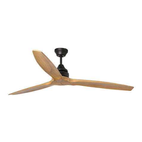
Skyfan SKY903WH User manual

INSTRUCTION MANUAL
Intelligent energy saving DC technology
With LED (-L) model
Images are for reference only and may vary slightly from actual product.
Ceiling Fan Installation Manual Rev 1.3
Thank you for purchasing this quality Ventair DC ceiling fan. To ensure correct function and safety,
please read all instructions before using the product and keep all instructions for future reference.
MODELS:
SKY903WH, SKY903WH-L, SKY903BL, SKY903BL-L
SKY1203WH, SKY1203WH-L, SKY1203BL, SKY1203BL-L
SKY1303WH, SKY1303WH-L, SKY1303BL, SKY1303BL-L, SKY1303TK, SKY1303TK-L
SKY1503WH, SKY1503WH-L, SKY1503BL, SKY1503BL-L, SKY1503TK, SKY1503TK-L
CAUTION
Read Instructions Carefully
For Safe Installation and Fan
Operation
MUST BE
INSTALLED BY
A LICENSED
ELECTRICIAN
DIY

2
WARNING:
FOR SAFE USE OF THIS FAN, AN ALL-POLE DISCONNECTION MUST BE
INCORPORATED INTO THE FIXED WIRING INACCORDANCE WITH THE WIRING RULES.
As outlined in clause 7.12.2 of AS/NZS 60335-1 for meeting the minimum electrical safety of
this standard.
Please note warranty will be void if installation is without an all-pole disconnection incorporated
in the fixed wiring in accordance with the wiring rules.
Example: If a fan is connected to a circuit that can be isolated via an all-pole safety switch at the
switchboard, then this is considered to be an all-pole disconnection to the ceiling fan electrical
circuit, meeting the requirements of clause 7.12.2 of AS/NZS 60335.1.
A single-pole switch on the active of the receiver input of remote control must also
beincluded in the wiring, and located in the same room as the ceiling fan.(see wiring
diagram)
1. The appliance is not intended for use by persons (including children) with reduced physical, sensory
or mental capabilities, or lack of experience and knowledge, unless they have been given supervision
or instruction concerning the use of the appliance by a person responsible for their safety.
2. Children should be supervised to ensure that they do not play with the appliance.
3. The structure to which the fan is to be mounted must be capable of supporting a weight of 20kg.
4. The fixing point on the ceiling, requires a solid bracing structure such as Timber noggins or joists.
The bracing should be butted up firmly and securely to the back of any non structural roofing panel
such as plaster or Gyprock to ensure safety and optimum performance of the fan.
5. The fan should be mounted so that the blades are at least 2.1m above the floor.
6. Only a licensed electrician should handle the installation.
7. WARNING: If unusual wobbling or oscillating movement is observed, immediately stop using the
ceiling fan and contact the manufacturer, its service agent or suitably qualified persons.
• Do not dispose of electrical appliances as unsorted municipal waste, use separate
collection facilities. Contact your local government for information regarding the collection
systems available. If electrical appliances are disposed of in landfills or dumps,
hazardous substances can leak into the ground water and get into the food chain,
damaging your health and well-being.
SAFETY PRECAUTIONS
2
SAFETY PRECAUTIONS
6. Only a licensed electrician should complete the installation.
8. WARNING: Light and fan must be connected to the same phase. Before servicing, ensure both light
and fan circuits are disconnected.

3
Unpack the fan and carefully identify the parts. Please refer to Fig 1.
Fig. 1
FAN WITHOUT LIGHT FAN WITH LED LIGHT
1. Mounting bracket x 1 1. Mounting bracket x 1
2. Pre-assembled fan motor, downrod, canopy
and bottom cover x 1
2. Pre-assembled fan motor, down rod, canopy
and LED light x 1
3. Blades x 3 3. Blades x 3
4. Remote control x1 4. Remote control x 1
5. Receiver x 1 5. Receiver x 1
6. Balancing kit x 1 6. Balancing kit x 1
7. Blade screws x 6 7. Blade screws x 6
8. Wood screws for mounting bracket x 2
Wood screw for safety wire x 1
8. Wood screws for mounting bracket x 2
Wood screw for safety wire x 1
Please Note: Check for any damage to the fan before installation.
Damage, marks or scratches are not covered by in home warranty. In this case ,product
should be returned to place of purchase for replacement.
BEFORE INSTALLATION
1. Mounting bracket x 1
2. Pre-assembled fan motor, down rod, canopy
and bottom cover x 1
3. Blades x 3
4. Remote Control x 1
5. Receiver x 1
6. Balancing Kit x 1
7. Blade screws x 6
8. Wood screws for mounting bracket x 2
Wood screw for safety wire x 1
1. Mounting bracket x 1
2. Pre-assembled fan motor, down rod, canopy
and LED light x 1
3. Blades x 3
4. Remote Control x 1
5. Receiver x 1
6. Balancing Kit x 1
7. Blade screws x 6
8. Wood screws for mounting bracket x 2
Wood screw for safety wire x 1
3
BEFORE INSTALLATION
Skyfan WITHOUT LIGHT Skyfan WITH LIGHT
Unpack the fan carefully and identify all parts. Please refer to Fig 1.
Fig 1.
Please note: Check for any damage to the fan before installation.
Damage, marks or scratches are not covered by the in home warranty. In this case,
product should be returned to place of purchase for a replacement.
(5 x 16mm)
(6 x 50mm)
(6 x 50mm)
(6 x 50mm)
(6 x 50mm)
(2 pcs R03 1.5V AAA Batteries
included. Wood screws 4 x 25mm).
(2 pcs R03 1.5V AAA Batteries
included. Wood screws 4 x 25mm).
(5 x 16mm)

4
MOUNTING BRACKET
• The ceiling fan must be installed in a location so that the blades have a minimum 300mm spacing
from the tip of the blade to the nearest objects or walls.
• Secure the hanging bracket to the ceiling joist or structure that is capable of carrying a load of at least
20kg, with the two Fixing screws provided. Ensure at least 30mm of the screw is threaded into the
support structure.
NOTE: The bracket fixing screws provided are for use with wooden structures only. These
screws are designed specifically for this purpose, and use of other types of screws, ie, bugle
headed screw, may void the warranty.
For structures other than wood, the appropriate screw type MUST be used.
Securethesafetywiretotheceilingjoistorothersuitablefixingpoint.
Fig. 3
Angled Ceiling Installation
This fan hanging system supports a maximum 15-degree angled ceiling installation. (FIG 4)
Please note: the Tab (B) on the hang bracket that sits in the groove (A) on the hanging ball should be
positioned at the highest point to ensure correct operation. (FIG 6)
Fig 4 (show Fig 5 here also
INSTALLATION
Fg.
UP TO 20KG
This should come after
hanging the fan
4
MOUNTING BRACKET
The ceiling fan must be installed in a location so that the blades have a minimum 300mm spacing
from the tip of the blade to the nearest objects or walls.
Secure the hanging bracket to the ceiling joist or structure that is capable of carrying a load of at least
20kg, with the two Fixing screws provided. Ensure at least 30mm of the screw is threaded into the
support structure.
NOTE: The bracket fixing screws provided are for use with wooden structures only. These
screws are designed specifically for this purpose, and use of other types of screws, ie, bugle
headed screw, may void the warranty.
For structures other than wood, the appropriate screw type MUST be used.
Securethesafetywiretotheceilingjoistorothersuitablefixingpoint.
Fig. 3
Angled Ceiling Installation
This fan hanging system supports a maximum 15-degree angled ceiling installation. (FIG 4)
Please note: the Tab (B) on the hang bracket that sits in the groove (A) on the hanging ball should be
positioned at the highest point to ensure correct operation. (FIG 6)
Fig 4 (show Fig 5 here also
INSTALLATION
Fg.
UP TO 20KG
This should come after
hanging the fan
5
BLADE ATTACHMENT
1. Insert the blades (x3) into the blade holding slots on the motor housing, slide downward and click into
position‘.
2. Insert the 2 safety screws ,being careful not to over-tighten
3. Move motor housing canopy downward until covering the motor housing.
Lift the fan assembly onto the mounting bracket. Ensure that slot (A) of the hanger ball is fully
aligned/engaged with the Tab (B) of the mounting bracket (C) to prevent the fan from rotating when in
operation. (Fig.6)
Fig. 3
HANGING THE FAN
QUICK ‘CLICK’ BLADE INSTALLATION
Motor housing canopy
Safety screws
Slot
BEFORE INSTALLATION
PLEASE NOTE:
The bracket xing screws provided are for use with the wooden structures only. These screws are
designed specically for this purpose, and use of other types of screws, ie: Bugle headed screws may
void the warranty.
For structures other than wood, the appropriate screw type MUST be used.
QUICK ‘CLICK’ BLADE INSTALLATION
4

5
BLADE ATTACHMENT
1. Insert the blades (x3) into the blade holding slots on the motor housing, slide downward and click into
position‘.
2. Insert the 2 safety screws ,being careful not to over-tighten
3. Move motor housing canopy downward until covering the motor housing.
Lift the fan assembly onto the mounting bracket. Ensure that slot (A) of the hanger ball is fully
aligned/engaged with the Tab (B) of the mounting bracket (C) to prevent the fan from rotating when in
operation. (Fig.6)
Fig. 3
HANGING THE FAN
QUICK ‘CLICK’ BLADE INSTALLATION
Motor housing canopy
Safety screws
Slot
4
MOUNTING BRACKET
The ceiling fan must be installed in a location so that the blades have a minimum 300mm spacing
from the tip of the blade to the nearest objects or walls.
Secure the hanging bracket to the ceiling joist or structure that is capable of carrying a load of at least
20kg, with the two Fixing screws provided. Ensure at least 30mm of the screw is threaded into the
support structure.
NOTE: The bracket fixing screws provided are for use with wooden structures only. These
screws are designed specifically for this purpose, and use of other types of screws, ie, bugle
headed screw, may void the warranty.
For structures other than wood, the appropriate screw type MUST be used.
Securethesafetywiretotheceilingjoistorothersuitablefixingpoint.
Fig. 3
Angled Ceiling Installation
This fan hanging system supports a maximum 15-degree angled ceiling installation. (FIG 4)
Please note: the Tab (B) on the hang bracket that sits in the groove (A) on the hanging ball should be
positioned at the highest point to ensure correct operation. (FIG 6)
Fig 4 (show Fig 5 here also
INSTALLATION
Fg.
UP TO 20KG
This should come after
hanging the fan
5
HANGING THE FAN
ANGLED CEILING INSTALLATION
Lift the fan assembly onto the mounting bracket. Ensure that slot (A) of the hanger ball is fully
aligned/engaged with the Tab (B) of the mounting bracket (C) to prevent the fan from rotating
when in operation. Fig. 3)
This fan hanging system supports a maximum 15-degree angled installation. (Fig 4)
Please note: the Tab (B) on the hanging bracket that sits in the groove (A) on the hanging ball
should be positioned at the highest point to ensure correct operation.
Secure the safety wire to
the ceiling joist or other suit-
able xing point.
Highest Point
FINISHING THE INSTALLATION
• Complete the electrical connection at the mounting bracket terminal block.
NOTE: Skyfan DC is a class 2 electrical product.
(Refer to Fig 6.).
• Connect fan to the receiver (can be done before or after sliding receiver into place).
A. For fan models without light, plug cable marked ‘motor’ into remote control box.
See Fig 7.2
B. For fan models with light, plug cable marked ‘motor’ and ‘LED’ into remote control box.
See Fig 7.1
• Slide receiver into position in the hanging bracket making sure the AC input connecter on
the receiver is aligned with the AC port on the receiver. Refer Fig 7.1. on page 7.

6
Fig. 6.
Below is an example / guide for the electrical installer for maintaining CLASS 2 wiring to
the Skyfan DC’s terminal block.
STEP 1. Prepare the supply wires as
shown.
Note: 5mm bare copper (L & N), and
20-30mm single sheath (L & N) from the
double insulated supply cable.
20-30mm
5mm
Double Insulated supply cable
STEP 2. Prepare the supplied plastic tubing
(or similar) to the same length and place over
the 20-30mm single sheath insulation as
shown below, so that only 5mm bare copper
is protruding.
Note: Total outer diameter of each wire
should not exceed 3.00mm. Large diameter
will not t into the terminal block.
STEP 3. Lift the terminal latch clips and
FULLY insert the prepared active wires into
the terminal block on the mounting bracket,
and latch down the clip to lock the wires.
Note: About 7-8mm of the plastic tube (or
similar) insulation will be inserted as well. The
total diameter of each wire should not exceed
3mm as mentioned in Step 2.
Note: Ensure correct polarities, and ensure
the active wires are secured rmly into the
terminal block.
Fully Insert the
wires (including the
double insulated
heat tube section)
Approx 15mm
total.
Insert plastic sleeves over the
prepared active wires.
STEP 4. Apply 3-4 layers of electrical tape
overlapping the heat shrink insulation and
the double insulation of the supply cable
as shown.
Apply 3-4 layers
of electrical tape
making sure to
overlap the area
where the wires
branch from the
double insulation of
the supply cable.

7
After completing the electrical connection at the mounting bracket terminal block, connect the ceiling
fan wiring by the quick connector plug.
a. For fan models “without light”, plug ‘AC INPUT‘ and ‘MOTOR” into remote control box. (Fig. 7.1)
b. For fan models “with light”, plug ‘AC INPUT‘, ‘MOTOR’ and ‘LED' into remote control box. (Fig.
7.2)
Slide the canopy upwards into position over the mounting bracket then turn counterclockwise to twist
lock into position. Ensure all 4 Tabs on the mount bracket are located correctly into the slots on the
canopy. Canopy should be sitting approx. -3mm off the ceiling.
Ensure all wires are tucked neatly into canopy taking care not to cause damage.
.
Fig. 8
FINISHING THE INSTALLATION
Twistlock Canopy
Tab Slot
7
ELECTRICAL WIRING DIAGRAM
WARNING: FOR YOUR SAFETY ALL ELECTRICAL CONNECTIONS MUST BE UNDERTAKEN BY
A LICENSED ELECTRICIAN IN ACCORDANCE WITH AS/NZS 3000 WIRING RULES.
• Connect “LIVE” supply to the “L” of the terminal block on the mounting bracket. See Fig 6.
• Connect “NEUTRAL” supply wire to the “N” terminal block on the mounting bracket.
See Fig 6.
• Slide the canopy upwards into position over the
mounting bracket then turn counter clockwise to
twist lock into position. Ensure all 4 tabs on the
mount bracket are located correctly into the slots
on the canopy. Canopy should be sitting approx.
-3mm off the ceiling.
• Ensure all wires are tucked neatly
into canopy taking care not
to cause damage.
Please note:
This is only
applicable to
models with
LED light.
Fig. 7.1. Fig. 7.2.
7
After completing the electrical connection at the mounting bracket terminal block, connect the ceiling
fan wiring by the quick connector plug.
a. For fan models “without light”, plug ‘AC INPUT‘ and ‘MOTOR” into remote control box. (Fig. 7.1)
b. For fan models “with light”, plug ‘AC INPUT‘, ‘MOTOR’ and ‘LED' into remote control box. (Fig.
7.2)
Slide the canopy upwards into position over the mounting bracket then turn counterclockwise to twist
lock into position. Ensure all 4 Tabs on the mount bracket are located correctly into the slots on the
canopy. Canopy should be sitting approx. -3mm off the ceiling.
Ensure all wires are tucked neatly into canopy taking care not to cause damage.
.
Fig. 8
FINISHING THE INSTALLATION
Twistlock Canopy
Tab
Slot
7
After completing the electrical connection at the mounting bracket terminal block, connect the ceiling
fan wiring by the quick connector plug.
a. For fan models “without light”, plug ‘AC INPUT‘ and ‘MOTOR” into remote control box. (Fig. 7.1)
b. For fan models “with light”, plug ‘AC INPUT‘, ‘MOTOR’ and ‘LED' into remote control box. (Fig.
7.2)
Slide the canopy upwards into position over the mounting bracket then turn counterclockwise to twist
lock into position. Ensure all 4 Tabs on the mount bracket are located correctly into the slots on the
canopy. Canopy should be sitting approx. -3mm off the ceiling.
Ensure all wires are tucked neatly into canopy taking care not to cause damage.
.
Fig. 8
FINISHING THE INSTALLATION
Twistlock Canopy
Tab Slot
Fig. 8
Twist Counter
Clockwise to lock Twist
Clockwise
to unlock
Twistlock Canopy

8
REMOTE CONTROL OPERATION
1. Turn wall switch to ‘ON’ Fan
is now in standby mode.
A ‘beep’ will be heard.
If your fan has a light, the light
will illuminate in default setting
of 100% brightness in (NW)
Natural
white light.
FAN Fan ‘ON’ and ‘OFF’
F/R Forward - downdraft for cooling (summer mode)
Reverse - updraft for heat circulation (winter mode)
Increases fan speed until Max (speed 5)
Decreases fan speed until Min (speed 1)
TIMER Run on Timer with 12 setting options (1hr to 12hrs)
MODE ECO, SLEEP and NORMAL
ECO MODE 1st press - Fan will operate at peak energy efciency
level, usually somewhere between speeds 1 and 2
SLEEP MODE 2nd press - Fan will reduce by 1 speed every 30mins
until speed 1. (select preferred starting speed level rst)
NORMAL
3rd Press - cancels mode and returns to normal function
Please note:
‘SLEEP’ or ‘ECO’ modes.
FAN Fan ‘ON’ and ‘OFF’
Increases fan speed until Max (speed 5)
Decreases fan speed until Min (speed 1)
LIGHT Switches light ‘ON’ and ‘OFF’
Scrolls through colours: WW - NW - CW
Increases light brightness
Decreases light brightness
TIMER Run on Timer with 12 setting options (1hr to 12hrs)
MODE
F/R ECO, SLEEP, NORMAL and Forward/Reverse
ECO MODE 1st press - Fan will operate at peak energy efciency
level, usually somewhere between speeds 1 and 2
SLEEP MODE 2nd press - Fan will reduce by 1 speed every 30mins
until speed 1. (select preferred starting speed level rst)
NORMAL
3rd Press - cancels mode and returns to normal function
Please note:
‘SLEEP’ or ‘ECO’ modes.
F/R
Press and Hold for minimum 3 secs to change between Forward and
reverse. ‘F’ and ‘R’ will be visible on display screen
Forward - downdraft for cooling (summer mode)
Reverse - updraft for heat circulation (winter mode)
Fan Models Without Light
Fan Models With Light
+
+
+
+ and
+and
will not operate during
will not operate during
-
-
-
-
-
Note: Light will reactivate
at previous brightness and
colour (CCT) settings when
using handset only. Once wall
(isolation) switch has been
turned ‘OFF’ Light will default
back to 100% brightness
(NW) Natural white light.

9
REMOTE CONTROL OPERATION
The SkyfanDC Remote control comes pre-paired at the factory and is ready to use.
Pairing will only be required in situations mentioned below.
A remote control consists of two parts .
1. Handset (transmitter) controller.
For fan models “with light”
Fan ‘ON’ and ‘OFF’ (starts on speed 3)
LIGHT
Switches light ‘ON’ then scrolls through colours: WW
- NW - CW - OFF (starts on WW)
Scrolls through colours: WW-NW-CW (starts on WW)
+ Increases fan speed until Max (speed 5)
- Reduces fan speed until Min (speed 1)
+
Increases light brightness
-
Reduces light brightness
TIMER
Run on Timer with 12 setting options (1hr to 12hrs)
MODE F/R Presses to switch ECO, SLEEP and NORMAL
MODE ECO, SLEEP and NORMAL
ECO MODE 1st press - Fan will operate at peak energy efficiency
level, usually somewhere between speeds 1 and 2
SLEEP MODE
2nd press - Fan will reduce by 1 speed every 30 min
until speed 1. (select preferred starting speed level first)
NORMAL
3rdpress – Cancels Mode and returns to normal
function Please note; + and - will not
operate during ‘SLEEP’ or ‘ECO’ modes.
MODE F/R Long presses by 3 seconds to switch to Summer and
Winter modes
Forward-Downdraft for cooling (summer mode)
Reverse-Updraft for heat circulation(winter mode)
• A remote control consists of two parts.
1. Handset (transmitter) controller.
2. Receiver. Receives messages from the handset and is located in upper canopy
of the fan.
• The Skyfan DC remote control comes pre-paired at the factory and is ready
to use.
Pairing will only be required in situations mentioned below.
1. Using 1 remote handset to control 2 or more Skyfan DC Ceiling fans
• Choose the fan you wish to pair with your handset.
• Turn isolation switch ‘ON’ and within 20 seconds press and hold on the
remote for 3 seconds. The fan will emit a ‘beep beep’ sound to indicate
the pairing process is activated.
• Press and change the speed of the ceiling fan via the remote to check the
operation and successful pairing.
2. Loss of function or control between hand piece and receiver
• Try the re-pairing process as outlined above (point 1). If the problem persists,
call Ventair technical support on 1300 665 926.
3. Replacing an old or damaged handset
• If you are replacing a handset only (not the receiver), the repairing process
(point 1) will need to be performed before operation of the fan is possible.
9
REMOTE CONTROL OPERATION
Handset
Reciever

10
MAINTENANCE
CARE AND CLEANING:
NOTE: Always turn OFF the power at the mains switch before performing any maintenance
or attempting to clean your fan.
• Every 6 months, periodic cleaning of your ceiling fan is the only maintenance
required. Use a soft brush or lint free damp cloth to avoid scratching or marking the
surface. Please turn off electricity power when you do so.
• Do not soak or immerse your ceiling fan in the water or other liquids. It could
damage the motor or the blades and create the possibility of an electrical shock.
• Ensure that the fan does not come in contact with any organic solvents or cleaners.
• To clean the fan blade, wipe with only a damp clean cloth with NO organic solvents
or cleaners.
• The motor has a permanently lubricated ball bearing so there is no need to oil.
IMPORTANT FACTS
Fan Operation:
Skyfan DC has been designed to optimize airow with minimal amount of energy usage.
A ceiling fan rotates much more slowly than traditional style wall, pedestal or desk fans;
ceiling fans cool people effectively by introducing slow movement ,with high airow, into
the otherwise still, hot air of a room, creating a natural evaporative cooling effect. Fans never
actually cool air, like air-conditioning equipment, but use signicantly less power.
Normal Wear and Tear
Over time, moving parts may become slightly loose or worn creating small increases in
noise or movement. Fan operation may also be affected by accidental contact by persons
or foreign objects. These conditions are not covered under warranty, but a little care and
maintenance can reduce or prevent these problems from arising
Night Noise
All electric motors, including fan motors make some noise however, the Skyfan DC fan motor
is not susceptible to the noise problems that are commonly experienced with typical Higher
wattage, heavier AC type ceiling fan motors. The Skyfan DC Range are one of the quietest
fans available and are ideal for all areas of the home especially bedrooms where noise is a
crucial consideration.

11
TECHNICAL INFORMATION
Ceiling Fan
Model Rated Voltage
Rated
Power
(Motor)
Rated Power (Lamp) Fan Weight
(Kg)
SKY903WH 220-240 VAC 32W N/A 3.82
SKY903WH-L 220-240 VAC 32W 20W, LED, 3000K, 4000K, 5000K 4.16
SKY903BL 220-240 VAC 32W N/A 3.82
SKY903BL-L 220-240 VAC 32W 20W, LED, 3000K, 4000K, 5000K 4.16
SKY1203WH 220-240 VAC 31W N/A 4.00
SKY1202WH-L 220-240 VAC 31W 20W, LED, 3000K, 4000K, 5000K 4.43
SKY1203BL 220-240 VAC 31W N/A 4.00
SKY1203BL-L 220-240 VAC 31W 20W, LED, 3000K, 4000K, 5000K 4.43
SKY1303WH 220-240 VAC 31W N/A 4.05
SKY1303WH-L 220-240 VAC 31W 20W, LED, 3000K, 4000K, 5000K 4.39
SKY1303BL 220-240 VAC 31W N/A 4.05
SKY1303BL-L 220-240 VAC 31W 20W, LED, 3000K, 4000K, 5000K 4.39
SKY1303TK 220-240 VAC 31W N/A 4.05
SKY1303TK-L 220-240 VAC 31W 20W, LED, 3000K, 4000K, 5000K 4.39
SKY1503WH 220-240 VAC 43W N/A 4.50
SKY1503WH-L 220-240 VAC 43W 20W, LED, 3000K, 4000K, 5000K 4.70
SKY1503BL 220-240 VAC 43W N/A 4.50
SKY1503BL-L 220-240 VAC 43W 20W, LED, 3000K, 4000K, 5000K 4.70
SKY1503TK 220-240 VAC 43W N/A 4.50
SKY1503TK-L 220-240 VAC 43W 20W, LED, 3000K, 4000K, 5000K 4.70

12
WARRANTY INFORMATION
• If you consider there are faults relating to the installation, contact your installer to
rectify.
• If you consider there is a manufacturer defect to the fan motor, contact the
warranty service line on 1300 665 926, or submit a warranty claim at
www.ventair. com.au/warranty
You will need to provide the following information:
• The name and contact details of the licensed electrician installer
• The brand, model number and serial number (on motor housing)
• The date and place of purchase of the unit.
• The owners name, address and telephone contact numbers.
• The nature of the fault.
The cost of a service person will only be paid for manufacturer defect.
Once a service person has been out, if any fault is found to be an installation or user
fault, the charges will be applied to the fan owner.
Other manuals for SKY903WH
1
This manual suits for next models
19
Table of contents
Other Skyfan Fan manuals
Popular Fan manuals by other brands
AFK
AFK DVT-40 instruction manual
ergovent
ergovent RONDO-160 installation guide

Premium
Premium PFB2000 Use & care manual

Kichler Lighting
Kichler Lighting Canfield Patio 310192 instruction manual

AirScape
AirScape 3400 VENTURA Installation and operation manual
SmartRef
SmartRef RV-200B Comfort Plus installation instructions


