Skysun Hobbies Pitts 150cc User manual
1

Caution!
1 You should not regard this plane as a toy!
2 To ensure safety, please read this instruction manual thoroughly
before assembly.
3 Building and operating a model plane requires diligent practice and
correct guidance. An inexperienced flyer can cause serious injury
and property damage.
4 Seek the assistance of an experienced RC pilot or model airplane
club for help with assembly, operation and maintenance to ensure
your flying experience is both enjoyable and safe.
5 Fly only in AMA (Academy of Model Aeronautics) approved areas.
Approved areas or areas approved by the Model Association of
your country.
2

Main Landing Gear and Tail Wheel Unit
Tail Wheel Unit
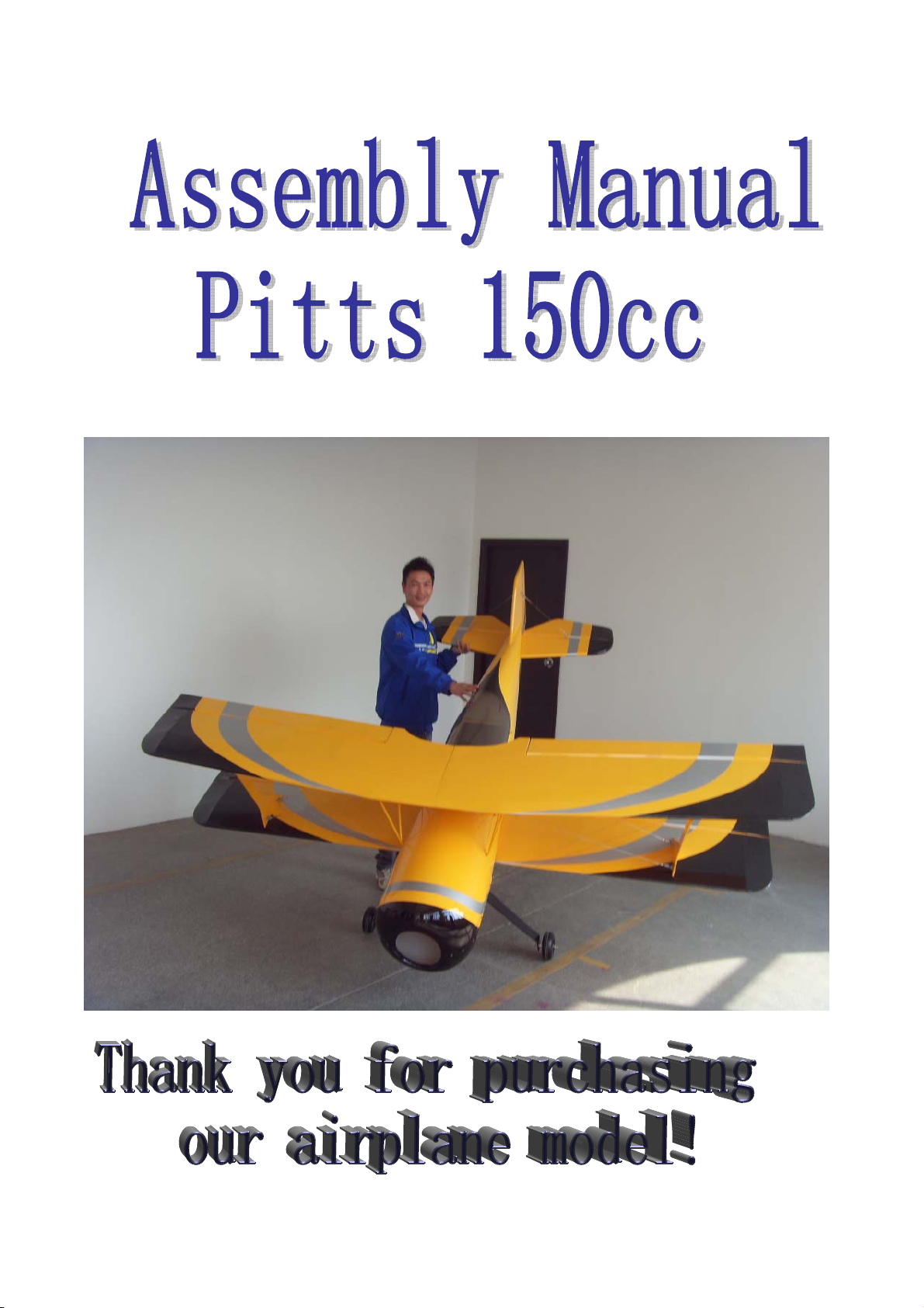
1
2
3
Drill a hole and make it fit
the steering tube.
Do not glue it into position untill the tail
wheel installation step is completed.
Assembly photo for the tail
wheel parts.
Use the tail wheel bracket as
a template and drill holes for
the mounting bolts.
3

4
5
6
7
Insert the steering arm into
the rudder steering tube and
position the tube ready for
gluing. Tighten the set nuts.
Epoxy the steering tube in
place as shown.
Install the blind nuts through
the openning in the rear of
the fuselage.
Attach the tail wheel bracket
and secure the bolts with
Blue Loctite.
Install the hatch with 4 self-
tapping screws
4

Main Landing Gear Istallation
1
2
All parts for the main landing
gear
Install the landing gear in the
pre-drilled holes with the
supplied bolts and locking
nuts.
Secure the bolts with Blue
Loctite
Install the landing gear axles
with lock nuts but do not
tighten yet.
5

3
4
5
6Mount the wheel pants and
secure the bolts with a drop
of Blue Loctite.
Install the wheel and tighten
the collar set screw using a
drop of Blue Loctite. Make
sure the wheel rotates freely.
Slipping the wheel pant over
the axles and mark the
position for the two attached
bolts.
Drill the holes for the
attached bolts and install the
blind nuts as shown.
6
Rudder Installation
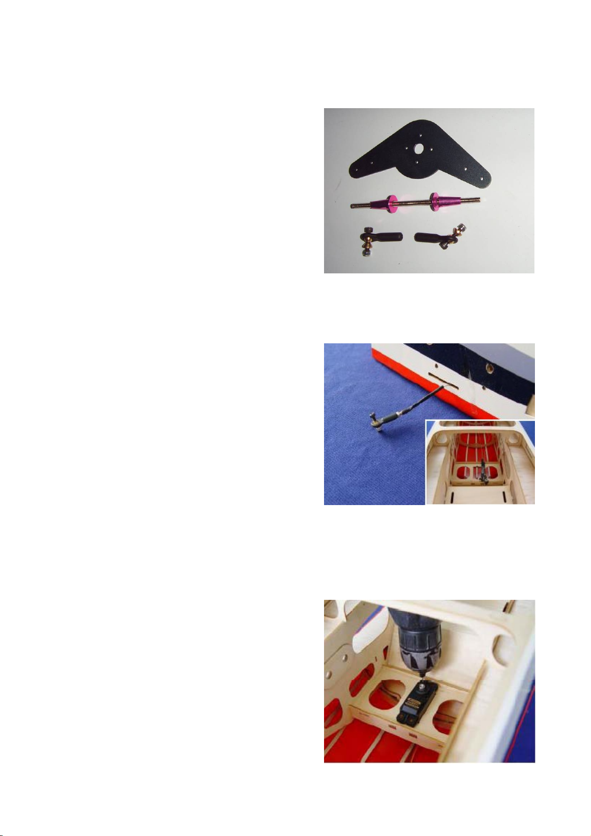
1Drill holes for the mounting
screws. Fit the servos as
shown with the servo label
facing the rudder. Harden the
area around the holes with a
drop of thin CA.
Parts for Rudder installation
The rudder cables and
couplers have been pre
installed as shown
7

2
3
4
Use brass crimps on each
cable and thread, the cable
through the end of the pull-
pull connector.
Crimp the brass tube with a
crimping tool or pliers
A drop of thin CA may be
applied to the brass tube to
help secure the cable
8

5
6
Install the rudder ball links
with bolts and locking nuts.
Check the pull-pull cables.
Rudder and the rudder servo
should both be in the neutral
position.
9
Stabilizer Installation
1
2
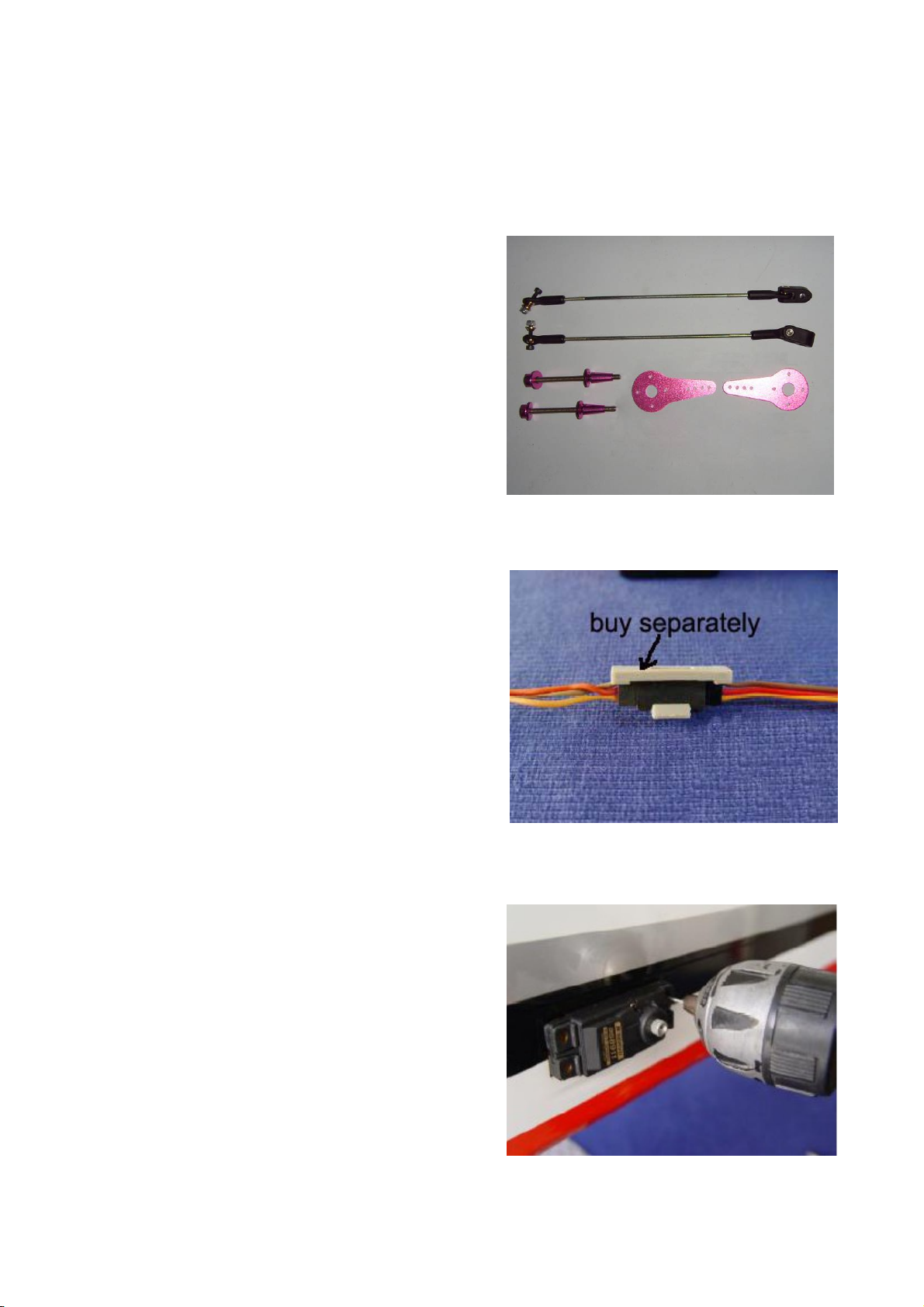
Use the safety clips (buy
separately) to secure the
servo and servo extension.
Parts for stabilizer
Install servos as shown with
the servo label facing the
rear of the fuselage.
10

3
4
Attn:
Repeat the previous steps
for the other wing.
Install the stabilizer tube and
bolts.
Install the stab with
mounting bolts and washers.
Assembly the servo arm in
the vertical position as
shown. Adjust the pushrod
length so that the servo and
elevator are both in the
neutral position.
11
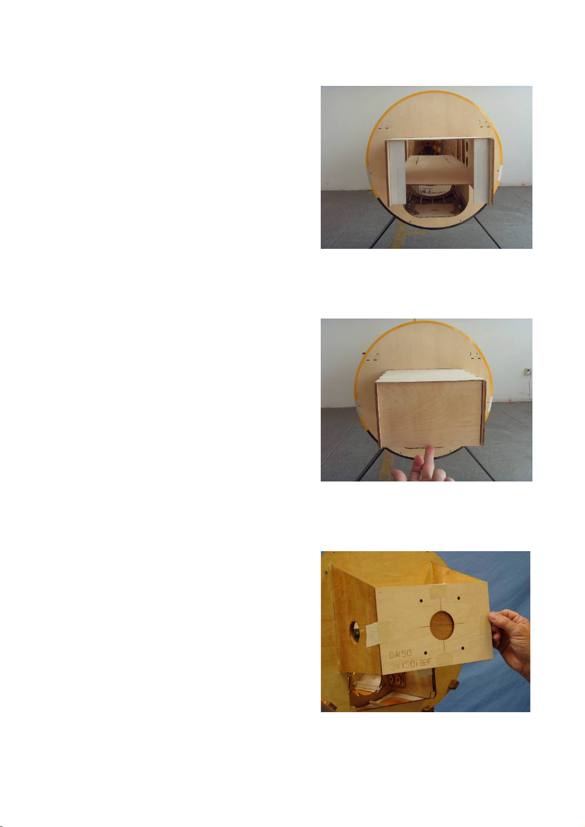
Engine Installation
1
2
3
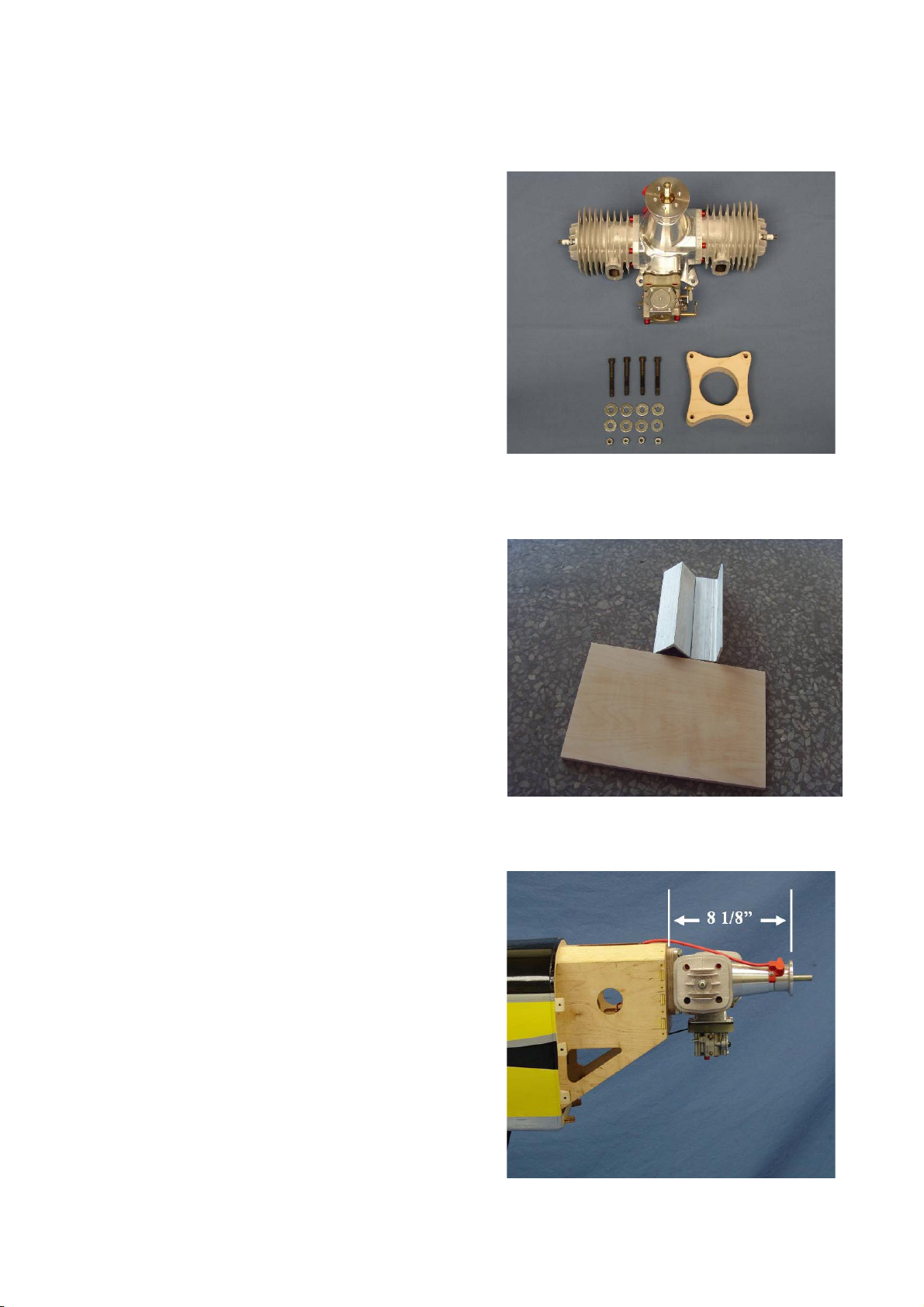
Illustrations for a DA-150
installation are provided
below. Gather the
engine,mounting hardware
and supplied DA 150
hardwood mounting spacer
block.
Find out the parts of the
firewall.
The required distance from
the front of the firewall to the
front of the prop mount on
the engine is 8 1/8” as
shown.
12
4
5
6
Install the aluminum angel
with right distance. And use
screw to fix it up.
fix the aircraft plywood as
firewall onto the aluminum
with screw.
Draw the mounting template
hole for the engine.
13

7
8
1
Install the canister headers to the
engine cylinder heads.Attach the
throttle pushrod to the engine
throttle arm as shown. Layout the
location of the throttle servo and
throttle pushrod.Ensure the servo
and pushrod donot interfere with
the canister muffler headers.
Install the throttle pushrod to the
engine throttle arm as shown.
You can also add a carbon fiber
tube to enhance the pushrod.
Muffler Installation
Gather the standard muffler
parts as shown:
Shown: DA150-C (Compact
muffler set)
Also fits: DA150 (Standard
muffler set)
14

2
3
1
Ignition Installation
Gather the ignition module,
ignition battery,
Use a drop of blue Loctite on
muffler bolts before
installation.
Install muffler cans using the
supplied gasket or high temp
silicon gasket material and
securely bolt to cylinder
heads as shown.
15

2
3
4
Roll the supplied foam rubber
to make a 4 layer pad as
shown. Make the pad slightly
larger than the ignition
module.
Install the ignition module
and the foam pad with a
nylon tie
Position the ignition module
inside the engine box to
allow both of the spark plug
leads to exit and properly
connect to the engine without
excess tension or chafing.
Mark the location for the
nylon tie mounting holes.
16

5
6
7
8
Connect the ignition cutoff,
regulator, and battery
Final ignition setup shown.
Use a 1/4” drill bit to drill the
ignition timing lead hole in
the firewall
Thread ignition connector
through firewall and connect
ignition timing connectors
with Safety Clip. Ensure the
connectors will not come
apart from vibration or light
tension.
17
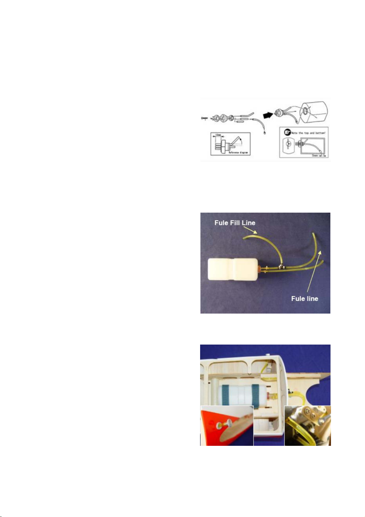
Fuel Tank
1
2
3
Install the inside parts of fuel
tank as shown.
Tighten the velcro ties
secure the fuel tank.
Assembly the outside fuel
pipe as shown.
18

Radio Installation
1
2
3
Gather the (2) radio
batteries, Power
Expander,switches and
power expander mounting
hardware
Attach power expander to
mounting rails
Mark the location of the
mounting rails
19

4
5
6
7
Install switches refer to
switch manufacturers
recommendations for specific
mounting methods.
Install un-supplied Velcro
straps.
Use 30 Minute epoxy to glue
mounting rails in place as
shown.
Install power expander using
four wood screws(not
supplied)
20
Table of contents
Popular Toy manuals by other brands

LEGO
LEGO 10695 Assembly instruction

Faller
Faller LENGMOOS STATION Assembly instructions

IMC Toys
IMC Toys BABYWOW Charlie user manual

Hobbico
Hobbico hammer Assembly and operation manual

The Cool Tool
The Cool Tool PLAYMAT instruction manual

MTHTrains
MTHTrains 263E STEAM ENGINE CONTEMPORARY VERSION operating instructions


Modellbau Laffont
Modellbau Laffont Z1821 manual

Hasbro
Hasbro Potty Chair instructions

Zohd
Zohd Nano Talon Quick start manual

Hasbro
Hasbro MARVEL STUDIOS THE INFINITY SAGA AVENGERS ENDGAME LEGENDS... quick start guide

Fisher-Price
Fisher-Price Jump 'n Dunk Basketball manual

E-FLITE
E-FLITE Beechcraft Bonanza 15e ARF Assembly manual