Skytron TVII User manual

Page 15
TVII
HANDLE CAMERA
SYSTEM
OWNERS MANUAL
12/03

Page 16

Page 1
SKYTRON, a Division of the KMW Group, Inc. (SKYTRON) warrants all new products sold by it directly or through a dealer or other
authorized representative, with exception to replacement parts, spares, bulbs (surgical lights), pads, and accessory items (surgical tables)
to be free from defects in material or workmanship, under normal use and service, for a period of two (2) years.This warranty shall include
the cost of repair or replacement of defective parts including the cost of service labor and travel time to the site of equipment use. Delays
caused by the user in accessing the equipment for repair will be chargeable at the normal hourly rate for service by SKYTRON’s authorized
service representative.The warranty period shall begin with the initial operation or one (1) year after receipt of the product, whichever shall
occur first.
Replacement parts, spares, bulbs (surgical lights), pads and accessory items (surgical tables) are warranted to be free from defects in
material or workmanship, under normal use and service, for a period of ninety (90) days from receipt by the ultimate user, with exception
to replacement parts supplied by SKYTRON, for products under warranty, which shall be covered for any remaining period of the original
product warranty, or for 90 days, whichever is of greater benefit to the ultimate user.
SKYTRON’s responsibility and liability shall be limited to the repair or replacement of any part which we, SKYTRON, determine to be
defective within the applicable warranty period. Minor adjustments required as a result of normal wear during the use of the product within
the warranty period are not covered under warranty.The labor portion of this warranty is covered by SKYTRON’s Authorized Service Agent.
Repairs made by others are not authorized nor covered by SKYTRON with respect to labor costs.
SKYTRON shall not be liable for any other expense, loss or damage, whether direct, incidental, consequential or exemplary arising in
connection with the sale or use of or the inability to use SKYTRON products.
NO EXPRESS WARRANTY IS GIVEN BY SKYTRON WITH RESPECT TO ITS PRODUCTS EXCEPT AS SPECIFICALLY SET FORTH
HEREIN. ANY WARRANTY IMPLIED BY LAW, INCLUDING ANY WARRANTY OF MERCHANTABILITY OR FITNESS FOR A PARTICU-
LAR PURPOSE, IS EXPRESSLY LIMITED TO THE TWO-YEAR AND 90-DAY TERMS SET FORTH ABOVE. THE FOREGOING STATE-
MENTS OF WARRANTY ARE EXCLUSIVE AND IN LIEU OF ALL OTHER REMEDIES.
No dealer, agent, employee or other representative of SKYTRON is authorized to extend or enlarge this warranty.
SKYTRON STANDARD LIMITED WARRANTY
Although current at the time of publication, SKYTRON'S policy of continuous development makes this
manual subject to change without notice.
12/03
TITLE PAGE
Model ID................................................................................................................................................... 2
Special User Attention.............................................................................................................................. 3
Introduction .............................................................................................................................................. 4
Installation ................................................................................................................................................ 5
CameraInstallation............................................................................................................................. 5
Camera Removal ............................................................................................................................... 5
Counterweight .................................................................................................................................... 5
Sterilizable Cover ............................................................................................................................... 6
Operation ................................................................................................................................................. 7
Camera Control Unit ................................................................................................................................ 8
Camera Specifications ............................................................................................................................. 9
System Components ............................................................................................................................. 10
Wiring Diagram....................................................................................................................................... 11
Damaged Shipment Claim Procedure.................................................................................................... 12
TABLE OF CONTENTS
Page 2 MODEL ID
STELLAR SERIES
ST23TV
ST29TV
ST2323TV ST2923TV
ST29TV23 ST232323TV
ST292323TV ST29TV2323

Page 3
SPECIAL USER ATTENTION
Tohelpassurethehighestdegreeofoperatingsafety
for user and patient, SKYTRON has provided pre-
cautionary instructions throughout this manual.
Aswith theoperation ofany surgicallight, allhospi-
talpersonnel shouldbeawarethata certainamount
ofcare mustbeexercised tomaintainpatientsafety
andto keepyour SKYTRONSurgical Lightperform-
ing at peak efficiency.
The following is a summary of the important pre-
cautionary instructions:
•Connectorfaceplatemaybe wallmounted,installed
in a cabinet or installed on a Skyboom carrier.
•Make sure Main Power Switch on the light fixture
Wall Control is in the OFF position before installing
or removing the camera.
•Make sure Camera Assembly is securely locked
in lighthead before moving lighthead into use posi-
tion.
•Sterilizablecover must beremoved prior to remov-
ing camera.
•Do not attempt to focus or position the lighthead
using the camera body.Damage to the camera ro-
tation motor may result.
•Do not push in the Camera Release Button on the
LightheadAttachmentRingabove thesterilehandle,
asthis will cause the camera to disengage from the
lighthead.
•Refer to Skytron Stellar Series or Millennium Gold
Series operators Manual for light fixture operation.
ML24TV
ML2424TV
ML242424TV
MODEL ID
MILLENIUM SERIES

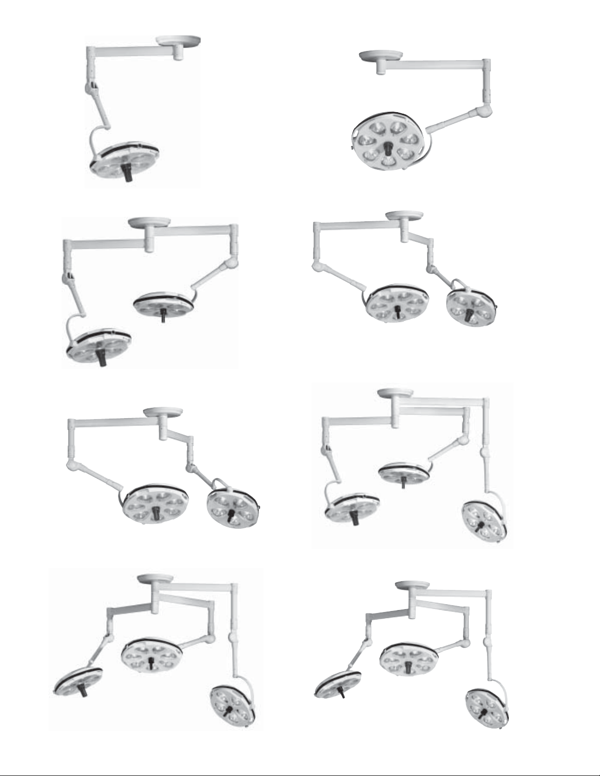
Page 4 INTRODUCTION
SKYTRON’S TVII Handle Camera System provides high quality video to camera ready (TV Series)
lightheads. The Sony single chip camera provides quality levels that are comparable to many 3 chip
systems. The system design permits transport from room to room, wherever other TV Series lightheads
are available. The camera control unit can be connected to any existing monitor. A convenient wall jack is
providedforcameracontrol connection. TheTVIIsystem canbe usedon SKYTRONStellarseries(ST23TV
and ST29TV) or Millennium Gold series (ML24TV) camera ready lightheads (ST23TV lighthead shown in
thispublication). TheTVlightheads maybesingle radialarmmounted, partof a multiplelightheadfixture or
combined with a SKYTRON Skyboom on a Central mount fixture,
The TV series lighthead option includes the Cam-
eraReady Lighthead,a counterweightfor usewhen
thelight isto be operatedwith thecamera removed,
a sterilizable camera cover that is used for a posi-
tioning/focushandleand aconnector faceplate with
a 50 foot coaxial cable that connects to the cam-
era/lightfixture.
The connector faceplate allows a quick connect or
disconnect point for the camera control unit. The
faceplate is mounted near where the camera con-
trol unit is to be located. It can be wall mounted,
installedwithin acabinetsuch asa nurse documen-
tation center or installed on a SKYTRON Skyboom
Equipment Carrier. Refer to page 10 forTV system
components.
The TVII Handle Camera system consists of the
camera, a camera control unit and a control cable.
The camera mounts in the center of the lighthead
and the sterilizable cover allows sterile positioning
and focus control for the lighthead.
Figure 1.TVII Handle Camera in ST23TV Lighthead

Page 5
Camera Installation
CAUTION
Make sure Main Power Switch on the
light fixture Wall Control is in the OFF
positionbeforeinstalling orremoving the
camera.
Use the following procedure to install the camera
system.
CAUTION
Make sure Camera Assembly is se-
curely locked in lighthead before mov-
ing lighthead into use position.
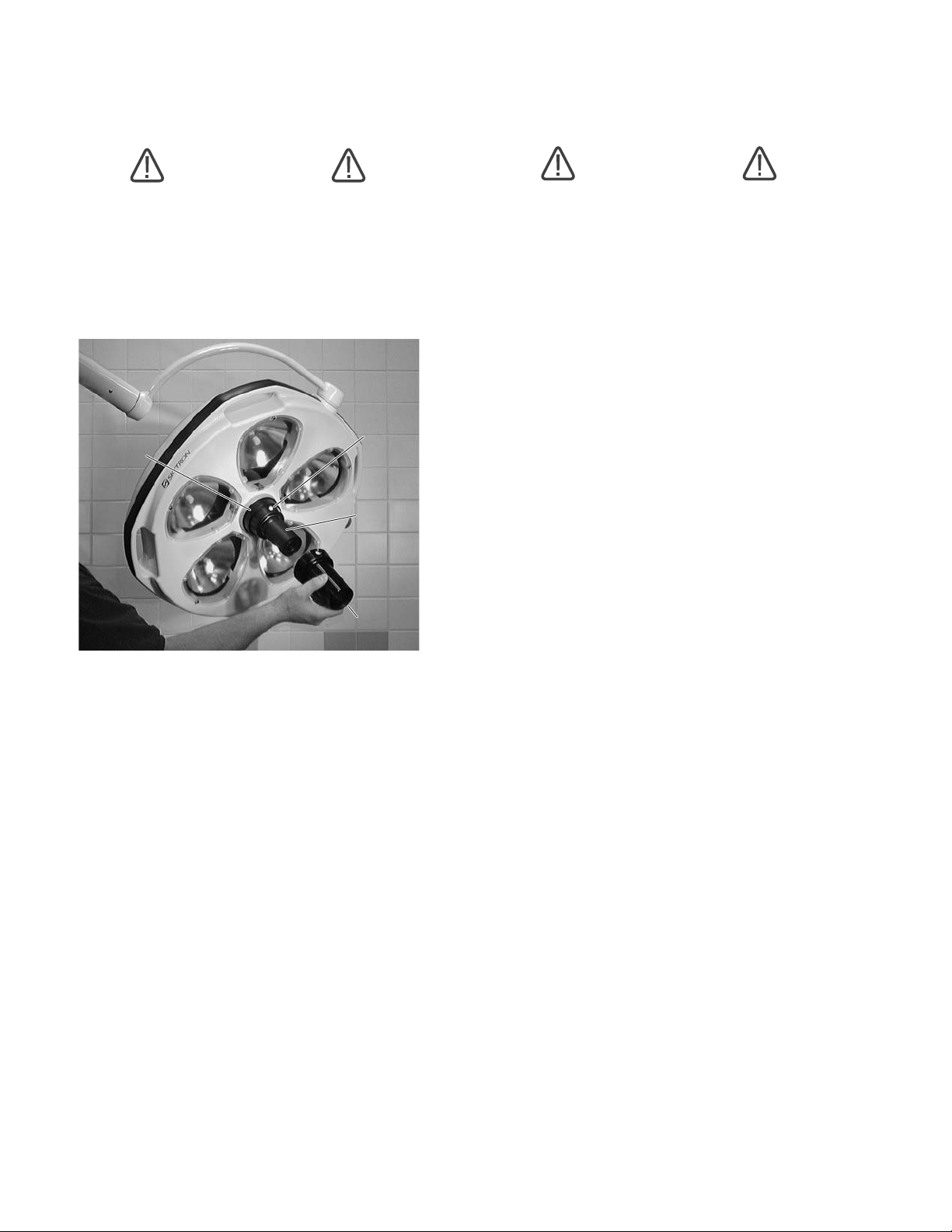
Camera Removal
Toremovethe cameraassemblyfromthelighthead,
hold the camera firmly, and press the camera re-
lease button on the lighthead attachment ring (fig-
ure 3). Carefully pull the camera assembly straight
out of the attachment ring.
NOTE
Sterilizablecover mustbe removedprior
to removing camera.
Counterweight
Thecounterweight mustbeinstalled tomaintainthe
proper weight required to balance the lighthead
when the camera is not installed.
Install the counterweight in the lighthead and en-
sure that it is fully engaged by pulling and slightly
turning it. Refer to figure 4.
To remove the counterweight from the lighthead,
hold the counterweight firmly, and press the cam-
era release button on the lighthead attachment ring
(figure 3).
Figure 2.
Figure 3.
LIGHTHEAD
ATTACHMENT RING CAMERA RELEASE
BUTTON
Move lighthead to the full down position, and turn
the lighthead so it faces up as shown in figure 2.
Insert the Camera Assembly into the lighthead at-
tachment ring. Push and twist the camera to lock it
into position. Pull out on the camera to verify that it
is fully locked into position.
Figure 4. Counterweight
INSTALLATON
COUNTERWEIGHT
Page 6
Figure 5.
LIGHTHEAD
ATTACHMENT
RING
COVER
LOCKING
PINS
CAMERA
ASSEMBLY
STERILIZABLE
COVER
Sterilizable Cover
CAUTION
Do not attempt to focus or position the
lighthead using the camera body. Dam-
age to the camera rotation motor may
result.
The camera has a sterilizable cover that, when in-
stalled, allows sterile positioning and focus control
for the lighthead. There is also a non-sterile focus
knobon the lighthead.
Toinstallthesterile cover, aligntheholes inthecover
with the cover locking pins on the camera attach-
ment ring and slide the cover on until it locks on the
two pins. See figure 5. To remove the sterile cover,
push the two white pins in and remove the sterile
cover.
CAUTION
Do not push in the Camera Release
ButtonontheLightheadAttachmentRing
above the sterile handle, as this will
causethe camerato disengagefrom the
lighthead.
Recommended sterilization parameters for the
sterilizable cover:
a. Prevac, 270° F, 4 minutes
b. Gravity Wrapped, 250° F, 30 minutes
c. Gravity Flash, 270° F, 3 minutes
Always consult current AORN journal recommen-
dations for proper sterilization procedures.

Page 7
SIDE
FOCUS KNOB
Figure 6.
NOTE
Refer to Skytron Stellar Series or Mil-
lennium Gold Series operators Manual
for light fixture operation.
OPERATION
Turn main power switch on at theWall Control. Ad-
just the intensity control. The intensity control must
be set to at least 20% for the camera to produce a
video signal.
The focus of the bulbs within the lighthead can be
adjustedby rotatingthe sterilizablecover orthe side
focus knob. See figure 6.

Page 8
Camera Control Unit
TheCamera ControlUnit providescontrols for cam-
era rotation, manual or automatic adjustment of Iris
(Aperture), Zoom and Focus. Refer to figure 9 for
control locations.
Description of Controls
MAIN POWER Switch -supplies powertothe cam-
era and control unit. Switch illuminates (green)
when power is ON.
CAMERA ROTATION - allows clockwise and
counterclockwise rotation of the camera. Press the
button for clockwise rotation. Press the for
counterclockwise rotation.
FOCUS - controls the focus of the camera lens.
When Main Power switch is turned ON the Focus
control is set to automatic. To operate the Focus
control manually, press the AUTO button. The Fo-
cus symbol will display on the monitor when in the
manual mode. Press the or button as re-
quired to obtain proper focus. Pressing the but-
ton sets the focus in the telephoto range. Pressing
the buttonsetsthe focusin thewideangle range.
Press the AUTO button again to activate the auto-
matic function.
Figure 9. Camera Control Unit, front view
Camera Control Unit Configuration
1. Attach the Coaxial Cable from the connector on
thefaceplate tothe camera controlunit (CCU). See
figure 7.
BNC
CONNECTOR
2. Connect the video out cable (SVHS or BNC)
from the camera control unit to the monitor.
3. Connect the power cord to the CCU and plug
into 120 VAC outlet. See figure 8.
Figure 8. Camera Control Unit, back view
120VAC INPUT
POWER CORD
CONNECTOR
BNC
VIDEO OUTPUT
CONNECTOR
BNC
CAMERA CABLE
CONNECTOR
SVHS
VIDEO OUTPUT
CONNECTOR
Figure 7. Camera Control Connector
Faceplate
MAIN
POWER
FOCUS
BRIGHT UP
D ZOOM
DISPLAY
CAMERA
ROTATION
ZOOM
AE
AUTO
IRIS DOWN FREEZE

Page 9
ZOOM - controls the image size. To make the sub-
ject larger, press the button. To make the sub-
ject smaller, press the button.
AE AUTO - allows automatic control of both IRIS
and BRIGHT functions.
BRIGHT - adjusts both the gain and iris using an
internal algorithm according to a brightness level
freelyset bythe user.Exposure iscontrolled bygain
when dark, and by iris when bright.
IRIS (Aperture) - controls the video signal bright-
ness by opening or closing the iris of the camera to
allow more or less light to enter the camera. When
Main Power switch is turned ON the Iris control is
set to automatic. To operate the Iris control manu-
ally, press the AE AUTO button. The “F” stop set-
ting will display on the monitor when in the manual
mode. Press the UP button to increase the bright-
ness. Press the DOWN button to decrease the
brightness. Press the AE AUTO button again to ac-
tivate the automatic function.
UP / DOWN - used with IRIS and BRIGHT options.
D ZOOM - controls digital zoom function. When
activated, extends zoom ratio from 10X to 40X.
DISPLAY - displays the current iris, zoom and fo-
cus settings on the monitor.
FREEZE - press to capture present view “snap-
shot”. Press again to resume normal operation.
TheHandle Camerasystem consistsof aLighthead
handle mounted, super compact color CCD cam-
era with a 10X zoom, high speed auto focus lens.
Controls are provided for camera rotation, focus,
zoom, Bright - Iris adjustment, digital zoom and
freeze. Composite and SVHS outputs are avail-
able.
SPECIFICATIONS:
Image Sensor 1/4" IT, Super HAD CCD
with Digital Signal Proces-
sor (DSP)
Video Signal Out Composite or SVHS
Picture Elements 768 (H) x 494 (V)
Resolution 470TV lines
Lens 10x Zoom f=4.2 to 42 mm
(F1.8 to F2.9)
Zoom Ratio 40x (10x optical, 4x digital)
Angle of View (H) Approx. 46 degrees (wide
end) to 5.0 degrees (tele
end)
Min. Object Distance 10mm (wide end) :
1000mm (tele end)
Iris Automatic/Manual
Min. Sensitivity 2.0 Lux
S/N Ratio 50dB +
White Balance Auto
Electronic Shutter 1/1 to 1/10,000 sec., 22
steps
Gain Auto/Manual (-3 to 28dB,
2dB steps)
AE Control Auto, Manual, Priority
mode, Bright, EV comp.
Back light comp.
Page 10
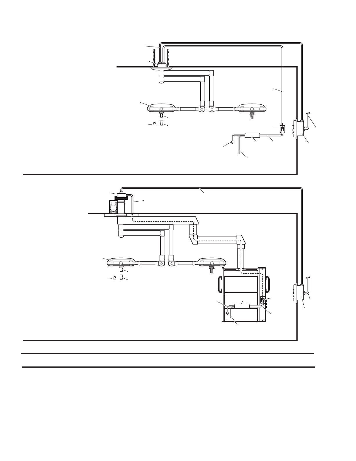
1 B1-420-08 CAMERA..............................................................................................1
2 B1-410-76 SLEEVE, sterilizable, camera cover ....................................................1
3 B1-420-02 COUNTERWEIGHT ............................................................................1
4 H7-010-47 CABLE ASSEMBLY, coaxial, RG59, 50 ft. ...........................................1
5 B1-420-30 CONNECTOR & FACEPLATE, camera control...................................1
6 B1-420-07 CAMERA CONTROL UNIT .................................................................1
7 B9-211-04 POWER CORD, camera control unit ...................................................1
8 H7-010-29 CABLE, coaxial, RG59 (specify length) ............................................. SP
H7-010-23 CONNECTOR, BNC, male ..................................................................2
Item Part No. Description Qty.
Lighthead J-Box
4
Wall Control
120V In
5
8
Video "out"
(customer supplied BNC or SVHS)
7
12 AWG Wiring
As Required
(customer supplied)
6
Camera Ready
Lighthead
Wall Control
120V In
Camera Control J-Box
412 AWG Wiring
As Required
(customer supplied)
Camera Ready
Lighthead
1
Video "out"
(customer supplied BNC or SVHS)
6
8
5
TV-II HANDLE CAMERA
SYSTEM COMPONENTS
(SKYBOOM CENTRAL MOUNT)
TV-II HANDLE CAMERA
SYSTEM COMPONENTS
32
7
1
32
NOTE
Connector Faceplate
may be
•Wall mounted
•Installed in a cabinet
•Installed on Skyboom
carrier
SYSTEM COMPONENTS

Page 11
TVII CAMERA SYSTEM
WALL
CONTROL
BOX
GWR
TIME
MENU
FOCUSIRIS ZOOM
CAMERA
ROTATION
MAIN
POWER
EXECUTE
DOWN
UP
DISPLAY
AUTO AUTO
DATE
1
2
3
4
5
6
1
RED - DC POWER +
BLACK - DC POWER
-
YELLOW - MOTOR POWER
BROWN - MOTOR POWER
GREEN - VIDEO OUT
ORANGE - VIDEO OUT
2
3
4
5
6
PCB #2
VPS (VIDEO POWER SUPPLY)
M
TS
POWER
CORD
CAMERA CONTROL UNIT
B1-420-07
AC INPUT 120V
HANDLE CAMERA
B1-420-08
CABLE #1
FACEPLATE
BNC
CONNECTOR
SIGNAL IN
DISPLAY VIDEO OUT
COMPOSITE,
S-VIDEO
BNC OR SVHS
PCB #1
VFB (VIDEO FILTER BOARD)
CAMERA
ROTATION
MOTOR CABLE #2
COAXIAL CABLE ASSEMBLY
RG59U - 50' H7-010-47

Page 12
DAMAGED SHIPMENT CLAIM PROCEDURE
Whenever a shipment suffers damage while in the
custodyof the transportation company, the respon-
sibilitylies withthetransportation company, and the
value of the damages can be collected from the
transportation company if the proper procedures
arefollowed.
When a shipment is received in a damaged condi-
tion and due to the appearance of the containers
such as a broken crate, torn wrapping, or smashed
carton,the contentsmayhavebeendamaged. That
factshould be noted on theBill of Lading offered by
the transportation company. An example of an ap-
plicable statement would be; "Received in good or-
der except as noted" or "Crate damaged, possibil-
ity of concealed damage." The addition of these
typesof statements on the shippingdocuments will
automatically give grounds for starting a claim.
Ifdamage cannot beidentified on theexterior of the
container,butisfoundwhenthe containerisopened,
further unpacking should be stopped immediately
and the container with all wrapping or packing ma-
terials should beheld. The transportationcompany
should be notified so an inspector can be sent.
Failureto followeither of thesetwoprocedures may
result in an inability to file a claim and collect for
damagedone. Returningthecontainertothesender
without such an inspection may prevent filing a
claim, because it will divide the responsibility for
damage and in many cases the
transportation company will return the shipment to
the sender without charge after the inspection.
The claim itself may be filed by either the shipper
or consignee, but the consignee must notify the
transportation company and the shipper that the
damage has occurred. Remember that refusal of
theshipmentorfailuretonote thepossibilityofdam-
ageonthe shippingdocuments mayjeopardize the
claim. Also, acceptance of a damaged shipment
which has been processed properly to allow for
filing a claim, will not jeopardize the position of the
consignee. In any case, SKYTRON will see that
damage which is not the fault of the consignee or
his agents is corrected, if the transportation com-
pany does not honor the claim, as long as
SKYTRON receives the full cooperation of the
consignee in filing the claim.
Some of the papers needed for filing a claim are in
thehandsof theconsingnee afterthe shipmenthas
been received. If SKYTRON must file a claim, we
will request these papers by name from the con-
signee at such time as the claim is under discus-
sion. We will require the originals of these papers
and not copies.
Knowledge of the procedures outlined above and
yourcooperation in submitting damagedshipment
claims will help both you, our customer, and
SKYTRON by assuring the integrity of our prod-
ucts from manufacturing to installation.

Page 13

Page 14
s:\commdept\1skytron\lights\Stellar\tvII\TVIIowner
500036th StreetS.E.,Grand Rapids,MI 49512
1-800-SKYTRONor1-616-957-0500 • FAX 1-616-957-5053
Table of contents


