SLE 350 User manual

Issue
2
SLE 350/500
Compressor
Service Manual

Page 2 of 42
Contact Information:
All rights reserved. No part of this publication may be reproduced, stored in any retrieval system, or transmitted in
any form or by any means, electronic, mechanical, photocopy, recording or otherwise, without prior permission of
SLE. © Copyright SLE 30/04/2007.
Manual : SM0020 Issue 2
SLE Part Nº: L0350/01 - L0500/01
SLE Limited
Twin Bridges Business Park
232 Selsdon Road
South Croydon
Surrey CR2 6PL
Telephone: +44 (0)20 8681 1414
Fax: +44 (0)20 8649 8570
Web site: www.sle.co.uk

Page 3 of 42
Contents
1. Warnings ..................................................................................................................... 5
1.1. General warnings ............................................................................................... 5
1.2. General safety warnings..................................................................................... 5
1.3. Safety warnings regarding the protection against electric current...................... 6
1.4. Description of symbols ....................................................................................... 7
2. Description .................................................................................................................. 9
2.1. Usage ................................................................................................................. 9
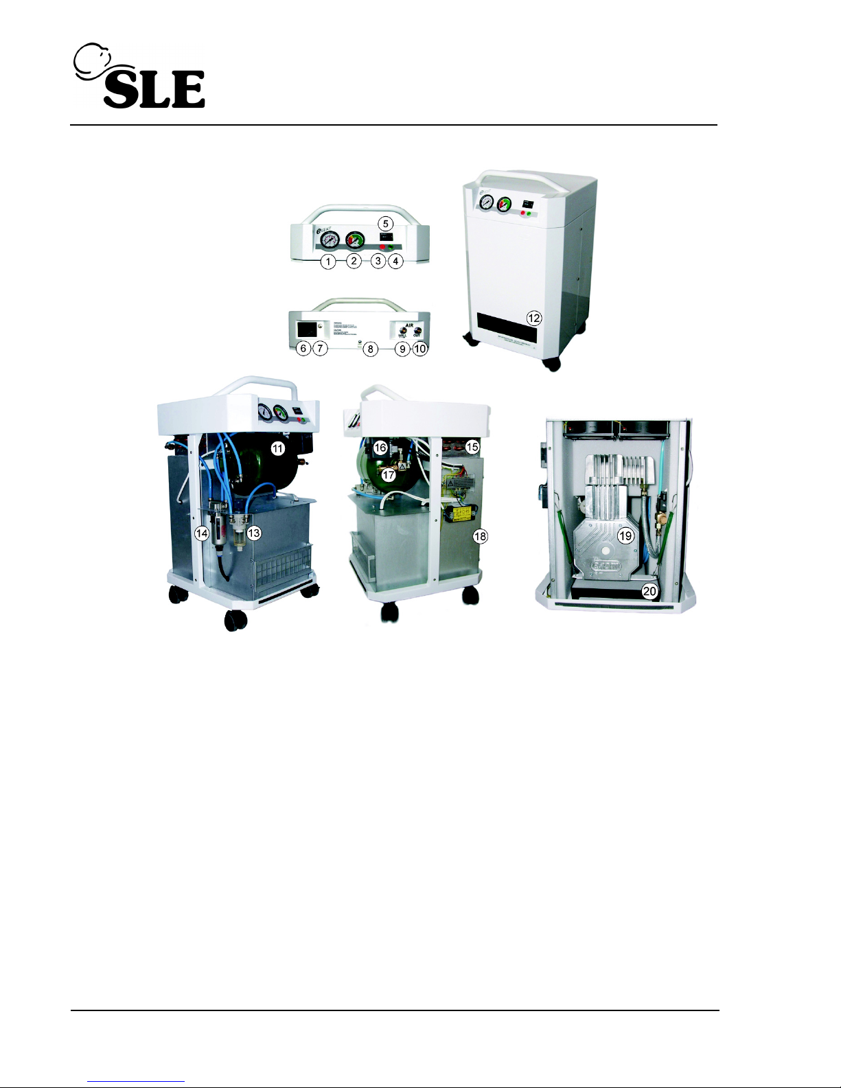
3. Description of compressor ........................................................................................ 10
4. Installation ................................................................................................................... 12
4.1. Environmental conditions ................................................................................... 12
4.2. Climatic conditions for operation ........................................................................ 12
4.3. Placing of the compressor.................................................................................. 13
4.4. Compressed air connection................................................................................ 14
4.5. Electric connection ............................................................................................. 15
4.6. First use.............................................................................................................. 15
5. Operating guidelines .................................................................................................. 16
5.1. Switching on the compressor ............................................................................. 16
6. Fault finding ................................................................................................................ 17
7. Maintenance ................................................................................................................ 19
7.1. Maintenance Intervals ........................................................................................ 19
8. Maintenance Programme ........................................................................................... 20
8.1. Intervals of service ............................................................................................. 20
8.2. Service kits ......................................................................................................... 21
8.3. Preparations for service. .................................................................................... 22
8.4. Cleaning and replacement of inlet filter .............................................................. 23
8.5. Check of safety valve ......................................................................................... 23
8.6. Replacement of filter inserts............................................................................... 24
8.7. Replacement of filter in blow filter....................................................................... 24
8.8. Replacement of filter in the pressure regulator................................................... 25
8.9. Regulation of output air pressure ....................................................................... 26
8.10. Replacement of pressure switch ...................................................................... 26
8.11. Adjustment of pressure switch ......................................................................... 26
8.12. Verification of tightness of joints and inspection of appliance .......................... 27
8.13. Checking of Capacity ....................................................................................... 27
8.14. Cooling failure alarm......................................................................................... 28
8.15. Cleaning the compressor.................................................................................. 28
8.16. Cleaning the filter ............................................................................................. 28
9. Replacement of piston with connecting rod and piston rings .............................. 29
9.1. Replacement of the bearing: .............................................................................. 30

Page 4 of 42
10. Storage and transport conditions ........................................................................... 30
10.1. Fixing of compressor before transportation. ..................................................... 31
10.2. Climatic conditions for storage and transport ................................................... 31
10.3. Storage ............................................................................................................. 31
11. Disposal of the appliance ......................................................................................... 31
12. Specification ..............................................................................................................32
13. Wiring Diagram ......................................................................................................... 33
14. Pneumatic Diagram .................................................................................................. 34
15. Equipment list ........................................................................................................... 35
15.1. Basic equipment ............................................................................................... 35
15.2. Additional accessories...................................................................................... 35
16. List of Spare Parts .................................................................................................... 36

Page 5 of 42
1. Warnings
1.1 General warnings
•The installation, operation and maintenance manual is an integral part of the appliance. It is
necessary to always keep this document close to the appliance. Strict observance of this
manual is a prerequisite for the correct operation of the appliance.
•The safety of operating personnel and failure-free operation of the appliance are ensured
only when using the original components. Only accessories specified in the technical
documentation or approved by the manufacturer must be used.
•When used with non authorized accessories or consumable material, the manufacturer
cannot assume responsibility for the safe operation and functionality of the device.
•The guarantee does not cover damage that originates from use of non authorized
accessories or consumables other than those recommended by the manufacturer.
•The manufacturer assumes responsibility regarding safety, reliability and function only if
- The installation, calibration, amendments, extensions and repairs are made by the
manufacturer or his representative or a service organization authorized by the
manufacturer,
- The appliance is used in accordance with the installation, operation and maintenance
manuals.
•The installation, operation and maintenance manual, at the time of printing, corresponds to
the design of the appliance and its state according to the relevant safety and technical
standards. The manufacturer reserves all copyrights for the given wiring schemes,
methods and names.
1.2 General safety warnings
The manufacturer developed and constructed the appliance so that damage would not occur
when the appliance is used for its intended purpose. The manufacturer considers it his
obligation to describe the following safety measures in order to avoid further damages.
•When operating the appliance, it is necessary to observe laws and regional regulations
valid in the place of usage. In order to ensure safe operation, the operator and user are
responsible for the observation of these regulations.
•The original packaging should be kept for the possible return of the unit. Only original
packaging guarantees an optimal protection of the appliance during transportation. If it
would be necessary to return the appliance during warranty period, the manufacturer is not
responsible for damages caused by incorrect packing.

Page 6 of 42
•It is necessary that the user ensures the appliance is safe to use prior to usage.
•The user must familiarize themselves with the correct operation of appliance.
•If a failure occurs in the operation of appliance, the user is obliged to immediately inform
the supplier of this event.
•This product is not intended for use in areas with the risk of explosion.
1.3 Safety warnings regarding the protection against electric current
•The appliance must only be connected to an appropriate power source that has correct
grounding.
•Prior to connecting the compressor, verify whether the mains voltage and frequency
specified on the apparatus are in accordance with the local supply.
•Prior to operation, check for possible damage to the appliance and the air connectors.
Damaged cables and sockets/plugs must be replaced immediately.
•In the case of a dangerous situation or a technical failure, immediately disconnect the
appliance from mains supply.
•During all repairs and maintenance:
- ensure that the mains plug is removed from the power socket
- pressure pipes must be air vented
- pressure must be released from pressure tank.
•This appliance can only be installed by qualified personnel.

Page 7 of 42
1.4 Description of symbols
For your information, the symbols below are used in the installation, operation and
maintenance manual, on packaging materials and on the product:
Symbol Description
Information or instructions to prevent any injury to health or material
damage to the compressor.
Alert against dangerous electric voltage.
Special information regarding the correct use of the appliance and other
warnings.
CE – marking
Attention! Hot surface.
Handling mark on packaging – Fragile, handle with care
Handling mark on packaging – This way up (Vertical position of freight)
Handling mark on packaging – Protect against humidity

Page 8 of 42
Handling mark on packaging – Temperature of storage and transport
Handling mark on packaging – Limited stacking
Mark on packaging – Recyclable material
Connection of protective ground wire
Alternating current
Symbol Description

Page 9 of 42
2. Description
2.1 Usage
•The SLE350 or SLE500 medical compressor, herein after referred to as the
compressor, is the source of clean, oil free pressurized air for use with
respiratory equipment. Due to the silent operation of the compressor, it is
possible to place the unit near the respiratory appliance beside the bed of the
patient.
The compressed air from the compressor is suitable for the operation of
respiratory appliances or similar apparatus.
•The compressor is to be operated in dry, aerated rooms where the ambient
temperature is between +15°C and +40°C, with the relative air humidity not
exceeding 70%.
•The compressor must not be exposed to rain. The appliance must not be used in
humid or wet environments. Furthermore, it is forbidden to use it in the presence
of flammable liquids or gasses.
•Before connecting the compressor to the respiratory device, it is necessary to
assess whether the compressor meets the requirements of the given device.
Please, refer to the technical data for this purpose.
•Usage, other than the compressors intended use is not considered to be safe.
The manufacturer is not responsible for the damages implied if the compressor
is used for other uses. Such a risk is assumed only by operator/user.

Page 10 of 42
3. Description of compressor
(1) PRESSURE - the output air (16) Pressure switch
pressure manometer (17) Safety valve
(2) HUMIDITY - the humidity (18) Internal back cover
indicator (performance) (19) Air pump
(3) Cooling failure indicator (20) Evaporative tray
(4) Power indicator
(5) Hour meter
(6) Main input, power switch, primary fuses
(7) Equipotential pin
(8) Socket for the supply lead
(9) WALL - input air coming from another
pressure air source (for example central distribution)
(10) OUT - output air from compressor
(11) Pressure tank
(12) Air intake filter
(13) Pressure regulator with microfilter
(14) Filter and water trap
(15) Cooler

Page 11 of 42
The appliance consists of an oil-free piston compressor and air chamber with the
relevant fittings, driven by a single-phase electric motor. It is placed in a box lined
with noise reducing material. In the rear area of box, there is a combined air filter
with a pressure regulator, by the means of which the trapping of humidity and its
automatic release to the evaporative vessel are ensured. The compressor thus
produces filtered compressed air without any traces of oil with reduced humidity.
The air pump sucks the atmospheric air through filters. Compressed air is cooled in
the cooler and continues through the filter and condensed liquid from the water trap
is automatically released to the evaporative tray. The air continue through the check
valve to the pressure tank and through the pressure regulator with microfilter to the
output. The fans operate while the air pump works, or also during the pause, when
the temperature in the cabinet is over 40°C. Any increase of temperature in the
cabinet over 80°C (cooling failure) is signalled by the red indicator and by acoustic
alarm. (The pressure switch control runs the air pump according to pressure in the
pressure tank). A safety valve prevents the maximum allowable pressure in the
pressure tank.
On the front of the compressor there is panel with an output air pressure gauge -
manometer, indicator for humidity, indicator of overheating of the compressor,
power indicator and a hour meter which indicates the length of use. On the rear
bottom of the cabinet there are: quick release coupling for output air from
compressor, quick release coupling for input air coming from another pressure air
source (for example central distribution), mains switch, safety fuses, socket, clip for
equipotential interconnection and socket for the supply lead.

Page 12 of 42
4. Installation
The compressor must be installed and put into operation for the first time by a
qualified person. Operating personnel should be trained about the usage and
common maintenance of the appliance.
Prior to first use, all transport fixings used during transport of the
compressor must be removed. If the compressor is switched on without the
prior removal of fixings, there will be a high risk of permanent damage to the
product!
It´s forbidden to use compressor after unpacking until it has been allowed to
acclimatize to the ambient temperature.
Do not obstruct the air intake filter and the ventilating outlets on the lower
part of appliance.
Do not lift the unit by the handle! Handle is for moving the unbraked product.
4.1 Environmental conditions
•The appliance can only be installed and operated only in dry, well-vented and
dust-free area.
•The compressor must stand on a flat, sufficiently stable base (note the weight of
compressor, see specification for details).
•The temperature in the room where the compressor is located must be between
+15°C to +40°C, otherwise failure-free operation of the compressor cannot be
guaranteed. Suitable ambient temperatures are +15°C to +25°C.
Caution – hot surface! During the operation of the compressor, parts of the
compressor reach high temperatures and are dangerous to the touch.
Danger of fire!
4.2 Climatic conditions for operation
Temperature +15°C to +40°C
Relative air humidity up to +70%

Page 13 of 42
4.3 Placing of the compressor
After unpacking, place the compressor upright with the castor wheels firmly on
the ground.
•Remove the front and back covers, unscrewing 6 screws on the side of
cabinet.
•Unscrew the four screws and remove the internal back cover.
•Remove all fixing elements (1) above and under the compressor.
•Insert the packaged evaporative tray (2) into the base.
•Insert the hose into the cut of the foam (3).
•Screw the internal back cover, connect the ground wire, screw the front and
back cover and insert the filter.
Please retain the fixing elements for future transportation of the compressor.
2
1
1
3

Page 14 of 42
4.4 Compressed air connection
The medical compressor is equipped with quick release couplings at the rear of the
cabinet.
To the ‘quick release’ coupling marked OUT connect the pressure hose leading to
the applicable appliance /respiratory device.
To the ‘fast-on’ coupling marked WALL connect pressurized air from a central
distribution system, if necessary. The air of this distribution system is automatically
connected through the compressor to the outlet OUT port. With such a connection,
the compressor serves as back up source of the compressed air. In the case of the
reduction of the pressure of air from central distribution system (under 5.0 bars),
compressor is automatically switched on and there is continuously pressurized air
with the required parameters at the output from compressor (OUT). Please ensure
that the compressor is connected to a mains plug to socket with nominal voltage
and frequency.
Please note that the air supply from the central distribution entering the
compressor must be medical grade air (dirt size, humidity). Do not use the
compressor to clean the air from central distribution! Breaching these
conditions could cause permanent damage to the compressor.
Air pressure in the central distribution must be in range 5 to 7 bar.
The compressor does not contain an alternate power supply (backup supply).
It is forbidden to cover the air vents on the back upper part of appliance.

Page 15 of 42
4.5 Electric connection
The compressor is delivered with a plug containing an appropriate protective
contact. It is essential to respect the local electrical regulations. The mains
voltage and frequency must comply with the information on the Data Label.
The power cord for the connection to the mains supply and the tubing of the
airhoses must not be broken. The power cord must not be stressed or have
any tension exerted upon it, and must always be free.
•If the appliance is connected to the mains supply by the means of a plug, the
socket must be accessible due to safety reasons, in order for the appliance to be
safely disconnected from the mains supply in the case of danger.
•The relevant current circuit (circuit breaker) must be safeguarded maximally to
10 A.
•Connection of the equipotential connection with other appliances must be
completed according to local valid electrical regulations.
4.6 First use
•Check whether all fixing screws used during transport were removed.
•Check that the connections of the compressed air supplies are correct.
•Check for proper connection to the mains supply.
•Switch on the compressor to position ‘I’.
After first putting the compressor into operation, the air chamber of compressor is
pressurized to a ‘switching-off’ pressure and the compressor will then be
automatically switched off. During the following time period the compressor works in
an automatic mode, i.e. according to the consumption of compressed air, the
compressor is switched on and off by the pressure switch.
During the operation, the appliance releases condensed water from the condenser
(filter) automatically to the evaporative vessel.

Page 16 of 42
5. Operating guidelines
In the case of danger, switch the appliance off at the switch and pull out the
mains plug.
After running, the compressor will have hot surfaces inside the cabinet. If
touched, there is a risk of being burnt.
Automatic operation. When the pressure in pressure tank falls down to a
‘switch on’ pressure, the compressor is automatically switched on. The
compressor is automatically switched off when the pressure increases to the
‘switching off’ pressure in the pressure tank.
5.1 Switching on the compressor
The compressor is switched on by mains switch by putting it to position ‘I’. Switching
on of the compressor is signaled by the pilot-light.
When the pressure of the air at the ‘Inlet’ port is reduced or if there is a reduction of
pressure in the air chamber, the compressor is switched on and the air chamber is
filled with compressed air. After the ‘switching-off’ pressure is reached, the
compressor is automatically switched off. Pressure of the output air from the
compressor indicates the manometer (1).
During the operation of the compressor, the pointer of the humidity indicator (2),
should be in the green zone. If the consumption of air from an appliance is larger
that the maximal outflow (see technical data for details), the pointer of indicator will
move from the green zone and the air from compressor will not reach the required
parameters of pressure dew point.
The hour meter (3) indicates total running time of the air pump.
12
3

Page 17 of 42
6. Fault finding
Prior to repairing the appliance it is necessary to reduce the pressure of the
air in the air chamber to zero and disconnect the appliance from the mains
supply.
Failure Possible Cause Troubleshooting
Compressor does not start
No mains voltage Switched off mains breaker in
distribution system
No current in pressure switch Check Supply
Fuse Blown – replace the
defective fuse
Loose wire terminal – tighten
Power cord defective – replace
power cord
Interrupted winding of motor,
damaged
thermal protection
Replace motor
Defective capacitor Replace capacitor
Jammed piston or another
rotary part
Replace damaged parts
Pressure switch does not switch
on
Change pressure switch
The pointer of humidity indicator
is out of green zone
Leakage of air from pneumatic
distribution system
Control of pneumatic
distribution system – seal loose
connection
Large consumption of com-
pressed air
Do not exceed max. flow
Compressor often
switches on
Leakage of air from pneumatic
distribution system
Control of pneumatic
distribution system – seal loose
connection
Leakage of check valve Clean check valve, replace
sealing, replace check valve
The operation of
compressor is extended
Leakage of air from pneumatic
distribution system
Control of pneumatic
distribution system – seal loose
connection
Worn-out piston rings Replace worn-out piston rings
Dirty Filters Replace the dirty filter with new
ones
Red indicator lights – state of
overheating
Dirty inlet filters Replace the dirty filter with new
ones
High ambient temperature of air
Cooling fans don’t work
Ensure suitable conditions of
the environment
Replace faulty fans
Replace faulty thermo -switch

Page 18 of 42
The manufacturer reserves the right to modify the appliance in a way that will not
impact substantially on the operation of the appliance.
Compressor is noisy
(knocking, metal noises)
Damaged piston bearing or
bearing on motor
Replace damaged bearing
Loose (cracked) rubber
suspension spring
Replace damaged spring with a
new one
Failure Possible Cause Troubleshooting

Page 19 of 42
7. Maintenance
7.1 Maintenance Intervals
Maintenance to be made Chapter Time interval To be performed by
Check of safety valve 8.5 on page 23 1 x per annum Qualified Expert
Cleaning input filter 8.4 on page 23. each 200 hours or as required User
Replacement of inlet filter 8.16 on page 28. Depends on local conditions, BUT At least
after 1000 hours running. User
Replacement of filter inserts 8.6 on page 24. after 1000 hours running or after one year Qualified Expert
Replacement filter regulator Service
documentation after 1000 hours running or after one year Qualified Expert
Testing of the tightness of joints
and inspection of appliance
Service
documentation after 1000 hours running or after one year Qualified Expert
Replacement of piston compl.
with piston rings
Service
documentation 2000 hours Qualified Expert
Release the air from the pressure
tank Service
documentation 2000 hours Qualified Expert

Page 20 of 42
8. Maintenance Programme
Repairs that exceed the framework of common maintenance must be
performed only by a qualified expert or the Customer Service Dept. of the
manufacturer. Use only spare parts and accessories approved by the
manufacturer.
Prior to any maintenance or repairs, it is necessary to switch off the
compressor and disconnect it from mains (pull out mains plug).
Before every service intervention it is required to remove the front and back covers,
disconnect the ground connector on the covers.
8.1 Intervals of service
Operation of service Chapter Time interval (hrs)
2000 4000 6000 8000 10 000 12 000
Check of safety valve 1 x per annum
Verification of tightness of
joints and check inspection of
appliance
2000 hours running or after 2 year
Replacement of service kit F
(filters)
X X X X X X
Replacement of service kit A X X X
Replacement of service kit B X X
Replacement of service kit C X
This manual suits for next models
1
Table of contents
Popular Air Compressor manuals by other brands

Ingersoll-Rand
Ingersoll-Rand XHP1070WCAT operating & maintenance manual

Bitzer
Bitzer 4FC-3.2 Series technical information

Emerson
Emerson VSG & VSSG Software manual

Gardner Denver
Gardner Denver HGR7-3K Operation maintenance manual & parts list

Titan
Titan TAC-2T owner's manual

Metabo
Metabo BasicAir 250 Original operating instructions