LW Compressors LW 170 E Nautic / AL User manual
C H A P T E R O V E R V I E W
Operating Instructions
..............................................................................................................
Spare Parts Lists
..........................................................................................................................
Options
(if equipped)
................................................................................................................
Attac ment
....................................................................................................................................
A
B
C
D
Manufacturer in terms of 97/23/EC
The full name and address of the manufacturer is:
Lenhardt & Wagner GmbH
An der Tuchbleiche 39
686 3 Hüttenfeld / Germany
Phone: +49 (0) 6 56 - 85 88 0 - 0
Fax: +49 (0) 6 56 - 85 88 0 - 14
E-Mail: service@lw-compressors.com
Internet: www.lw-compressors.com
Version: 11/1 -E
S E R V I C E I N F O R M A T I O N / W A R R A N T Y
Compressor information
Type designation
Serial number
Date of construction
Purc ase information
Purchase date
First commissioned on
Warranty period
Dealer's stamp
Warranty
L&W will uphold warranty claims made during a period of 1 months from the invoice date.
If the compressor was purchased from an official L&W dealer, the date on the dealer's invoice is
valid. Warranty claims can only be made on presentation of the original invoice.
Should verifiably defective parts have been delivered, we will decide to either replace the parts or
repair them. The resulting transport and assembly costs will be invoiced.
No reduction of the purchase price or changes to the contract can be made. The parts for which a
claim is being made should be kept safe by the purchaser and, when requested, sent to us at their
cost. Replaced parts become the property of L&W. If maintenance work is carried out without our
knowledge or permission by the purchaser or a third party, we are absolved from any liability for
warranty claims. As a matter of principle, warranty claims can only be made by the initial purchaser.
Version: 17101 -001E

Page A - 1
A
LW 170 E / LW 170 D Nautic
Version: 15.10.2019
Operating Instructions
Breathing Air Compressor
LW 170 E Nautic / AL
LW 170 D Nautic / AL

Page A - 2
A
LW 170 E / LW 170 D Nautic
Version: 15.10.2019
General Information an Technical Data
Genera Information / Description of Warning Symbo s .................................................................... 4
Drive motors ...................................................................................................................................... 5
Scope of De ivery LW 170 E Nautic / AL ............................................................................................. 6
Scope of De ivery LW 170 D Nautic / AL ............................................................................................. 7
Technische Daten ............................................................................................................................... 8
Unit Assemb y LW 170 E Nautic / AL .................................................................................................. 9
Phase Se ector Switch ...................................................................................................................... 10
Unit Assemb y LW 170 D Nautic / AL ............................................................................................... 11
F ow chart ....................................................................................................................................... 12
Safety Precautions
Intended Use / Operators ................................................................................................................ 14
Safety instructions on the unit ........................................................................................................ 15
Genera Safety Precautions ............................................................................................................. 16
Unit customised safety notices ....................................................................................................... 17
Maintenance instructions ............................................................................................................... 18
Transportation instructions / Safety regu ations .............................................................................. 19
Installation
Insta ation LW 170 E Nautic / AL ..................................................................................................... 21
Insta ation LW 170 D Nautic / AL .................................................................................................... 22
Dimensions LW 170 E Nautic / AL .................................................................................................... 23
Dimensions LW 170 D Nautic / AL .................................................................................................... 24
Minimum distances ......................................................................................................................... 25
Venti ation LW 170 E Nautic / AL ..................................................................................................... 26
E ectrica Insta ation LW 170 E Nautic / AL ............................................................................... 27 - 28
Operation
Important operation instructions ..................................................................................................... 30
First commissioning LW 170 E Nautic / AL ................................................................................ 31 - 32
First commissioning LW 170 D Nautic / AL ....................................................................................... 33
Dai y commissioning ........................................................................................................................ 34
Fi ing procedure .............................................................................................................................. 35
Switch off the compressor ............................................................................................................... 36
Reme ying faults
.............................................................................................................. 38 - 41
T A B L E O F C O N T E N T S

Page A - 3
A
LW 170 E / LW 170 D Nautic
Version: 15.10.2019
T A B L E O F C O N T E N T S
Maintenance an Service
Service, Repair and Maintenance ..................................................................................................... 43
Maintenance Lists / Maintenance Interva s ................................................................................ 44 - 47
Service Kits ...................................................................................................................................... 48
Check V-be t tension / Tension V-be t / Settings ............................................................................... 49
Compressor ubrication / Check oi eve ........................................................................................... 50
Oi change ....................................................................................................................................... 51
Manua condensation dump system ................................................................................................ 52
Oi / water separators 2nd stage - maintenance ............................................................................... 53
Fi ter housing / Fi ter cartridge ......................................................................................................... 54
Fi ter cartridge change ..................................................................................................................... 55
Fi ter housing - maintenance ........................................................................................................... 56
In et Fi ter ........................................................................................................................................ 57
Check or change fi ter in et .............................................................................................................. 58
Va ve heads and va ves .................................................................................................................... 59
Fan protection cover dismant ing / Mounting the fan protection cover ........................................... 60
Rep ace in et and out et va ve 1st stage .................................................................................... 61 - 62
Rep ace in et and out et va ves 2nd .................................................................................................. 63
Rep ace in et and out et va ves 3rd .................................................................................................. 64
Safety va ves ............................................................................................................................. 65 - 66
Pressure maintaining / non return va ve ........................................................................................... 67
Adjust pressure maintaining va ve ................................................................................................... 68
Lever fi ing va ve ...................................................................................................................... 69 - 80
O-rings - fi ing va ve and fi ing hose ............................................................................................... 81
Motor change .................................................................................................................................. 82
Pressure gas vesse test .................................................................................................................... 83
Maintenance records ................................................................................................................ 84 - 89
Storage
Conservation / storage of the compressor ....................................................................................... 90
De-conservation, commissioning ..................................................................................................... 91
Transportation instructions / Disposa / E ectric and e ectronic components .................................... 92

Page A - 4
A
LW 170 E / LW 170 D Nautic
Version: 15.10.2019
Warning
Indicates a potentia y hazardous situation which, if not avoided, cou d resu t in physica
injury or damage to the product or environment.
Caution
Indicates an imminent y hazardous situation which, if not avoided, cou d resu t in serious
injury, physica injury or death.
General Information
We strong y recommend reading this manua thorough y prior to operation and fo ow a the safety
precautions precise y. Damage resu ting from any deviation from these instructions is exc uded from
warranty and iabi ity for this product. Carry out other commissioning steps on y if you have fu y
understood the fo owing contents.
Before commissioning and using the unit, carry out a the essentia pre iminary work and measures
concerning ega regu ations and safety. These are described on the fo owing pages of this operati-
on manua .
G E N E R A L I N F O R M A T I O N
!
!
Note
Indicates additiona information on how to use the unit.
i
Description of marks an warning signs
The fo owing warning signs are used in this document to identify the corresponding warning notes
which require particu ar attention by the user. The warning signs are defined as fo ows:
Page A - 5
A
LW 170 E / LW 170 D Nautic
Version: 15.10.2019
Drive motors
LW 170 D Nautic / AL
Air coo ed diese engine (4,8 kW), separate stain ess
stee fue tank, pu start and 12V e ectric start
LW 170 E Nautic / AL
4,0 kW E-motor / 400V / 3 phase / 50 Hz (or 60 Hz),
fu y wired with cab e and 16A CEE p ug.
D E S C R I P T I O N

Page A - 6
A
LW 170 E / LW 170 D Nautic
Version: 15.10.2019
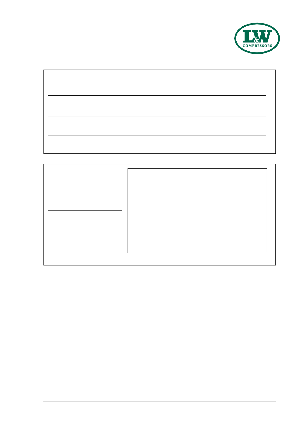
Scope of Delivery LW 170 E Nautic / AL
The user-friend y LW 170 E Nautic with e ectric drive is idea for mobi e app ications or occasiona
fi ing operations. It comes wired with power cab e, p ug and phase se ector.
Versions
Filling pressure versions:
• PN 225 bar
• PN 330 bar
• PN 225 / 330 bar
Specifications
Options
• Additiona fi ing hose c/w fi ing va ve
• Automatic stop at fina pressure
• Automatic condensate drain
• Automatic start system
• Switch over device for 200 or 300 bar
• Motor protection switch
• Specia vo tages / frequencies on request
• Additiona HP-Out et
• A uminium Frame
• E ectro Motor (Standard: 400V,3 phase,50Hz)
• Power cab e with p ug and phase se ector
• Start/Stop Switch
• Operating hour counter
• Stee frame
• Manua condensate drain
• Pressure maintaining and non return va ve
• 2x Fi ing hose c/w fi ing va ve and pressure
gauge
• Intermediate coo ers
• Stain ess stee pipes
• Oi - / Water separators after 2nd and 3rd
stage
• Safety va ves after each stage
• Fi ing pressure to your choice
(200 or 300 bar)
• Connections to your choice
(DIN 200 bar or 300 bar, CGA 200 bar or
300 bar and INT)
• Breathing air purification in accordance with
EN 12021
D E S C R I P T I O N

Page A - 7
A
LW 170 E / LW 170 D Nautic
Version: 15.10.2019
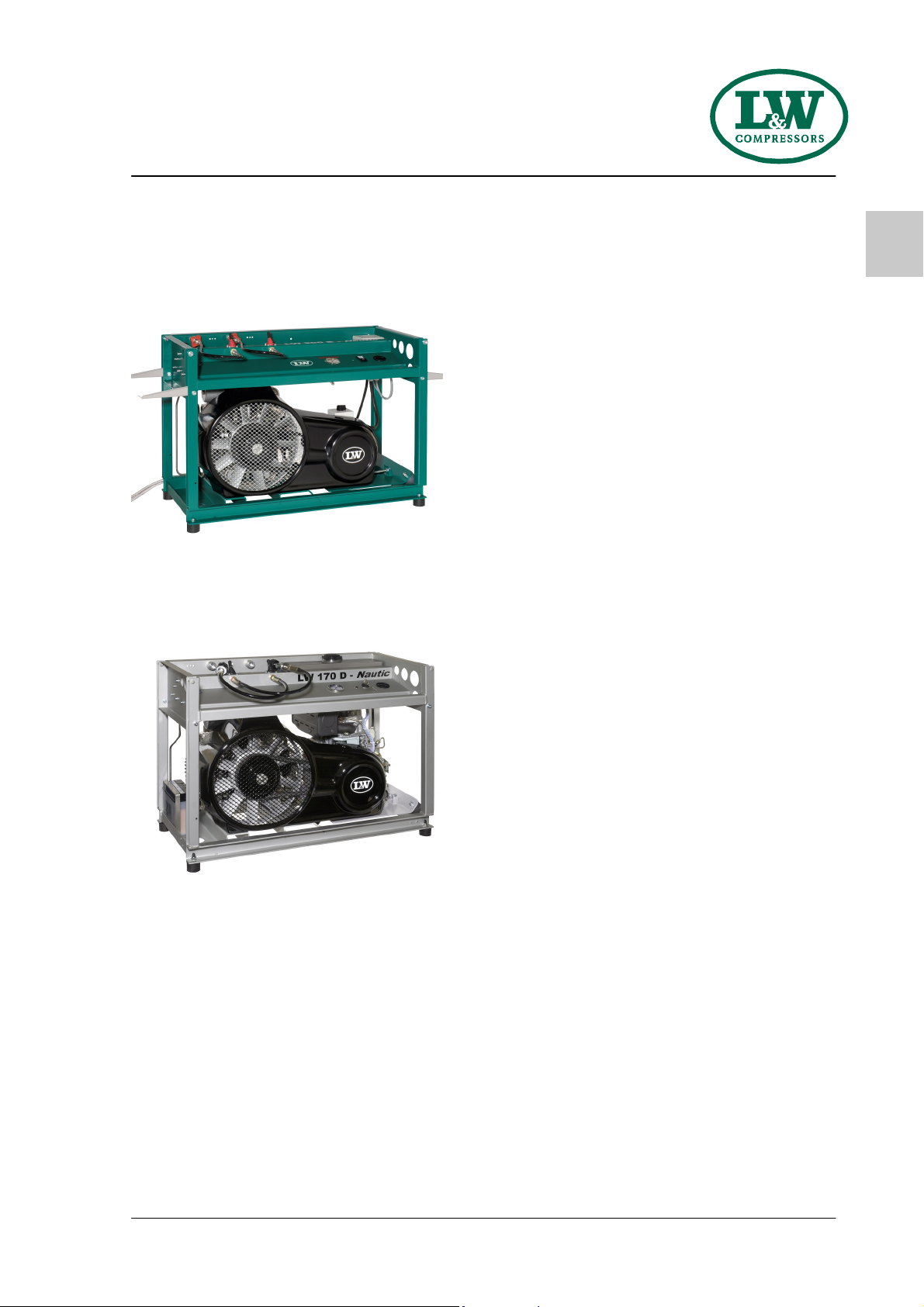
Scope of Delivery LW 170 D Nautic / AL
The user-friend y compressor with diese engine in a compact frame is a popu ar a ternative for
expeditions and safaris. The LW 170 D Nautic is portab e and therefore idea for mobi e app ications
or occasiona fi ing operations.
Versions
Filling pressure versions:
• PN 225 bar
• PN 330 bar
• PN 225 / 330 bar
Specifications
Options
• Additiona fi ing hose c/w fi ing va ve
• Additiona HP-Out et
• Automatic condensate drain
• Automatic stop at fina pressure
• Switch over device for 200 or 300 bar
• Motor protection switch
• A uminium Frame
• Air coo ed diese engine (4,8 kW) with
separate stain ess stee fue tank. Pu start
and 12V e ectro start
• Stee frame
• Manua condensate drain
• Operating hour counter
• Pressure maintaining and non return va ve
• 1x Fi ing hose c/w fi ing va ve and pressure
gauge
• Intermediate coo ers
• Stain ess stee pipes
• Oi - / Water separators after 2nd and 3rd
stage
• Safety va ves after each stage
• Fi ing pressure to your choice
(200 or 300 bar)
• Connections to your choice
(DIN 200 bar or 300 bar, CGA 200 bar or
300 bar and INT)
• Breathing air purification in accordance with
EN 12021
D E S C R I P T I O N

Page A - 8
A
LW 170 E / LW 170 D Nautic
Version: 15.10.2019
Technical Data
LW 170 E Nautic LW 170 D Nautic
Capacity [ /min]: 170 170
Max. Operating Pressure [bar]: 330 330
RPM [min
-1
]: 1530 1530
Number of Pressure Stages: 3 3
Cy inder Bore 1st Stage [mm]: Ø 72 Ø 72
Cy inder Bore 2nd Stage [mm]: Ø 28 Ø 28
Cy inder Bore 3rd Stage [mm]: Ø 14 Ø 14
Medium: Industria Air / Breathing Air
Intake Pressure: atmosphaeric
Oi Capacity [ ]: 0.8 0.8
Intake Temperature [°C]: 0 < +45 0 < +45
Ambient Temperature [°C]: +5 < +45 +5 < +45
Coo ing Air Vo ume [m³/h]: > 1200 > 1650
Vo tage:
400V / 3 phase / 50 Hz
-
Protection C ass Drive Motor: IP 54 -
Drive Power [kW]: 4,0 4,8
RPM Motor [min
-1
]: 2,890 2,890
Start: Start / Stop switch E ectric +Hand start
Noise eve [dB(A)]: 85 92
Dimensions W x D x H [mm]: 1030 x 500 x 730 1030 x 500 x 730
Weight [kg]: approx 135 approx 150
Content Vo ume Fi ter housing [ ]: 0.5 0.5
Technical Data
D E S C R I P T I O N
This manual suits for next models
1
Table of contents


