Slot SCP-1 User manual

Manual-UK 1.1.0 26/11/2010
SCP-1 1.1
1

Technical Specifications
Power supply 6 to 24V
Maximum motor current
(peak with analog st cartri ge) 6A
Operating temperature 0 to 40°
Weight 270 g
Warranty: two years. We reserve the right to refuse warranty repair if safety seal is broken.
This evice complies with RoHS irective. Do not immerse this controller in water.
No animals have been use for testing this controller, but several slot cars flew off the track in the
evelopment phase. The name SCP-1 means SeCaPelo-1 (Secapelo=Hair ryer).
Ma e in China.
Completely envisione , thought an esigne by Maurizio Ferrari, Maurizio Gibertoni, Cristian
Anceschi an Stefano Giorgi of Galileo Engineering srl, Via Cavallotti 16 – 42100 Reggio Emilia,
Italy - www.slot.it - [email protected]
Slot.it an the Slot.it logo are registere tra emarks belonging to Galileo Engineering srl.
Slot.it is in no way affiliate with Carrera, Hornby Hobbies, Ninco, Tecnitoys; Carrera Pro-X,
Carrera Digital 132, Hornby SSD, Ninco N-Digital, Tecnitoys The Digital System SDS, are
registere tra emarks belonging to their respective owners.
c. The complete printed manual is in English. Electronic versions of the manual in
Italian/Castellano/German can be downloaded from the Slot.it site: www.slot.it
The SCP-1 is contactless, friction free, with linear magnetic trigger position rea out (patent
pen ing), an features an interchangeable cartri ge system, to connect to either analog or igital
systems. The igital cartri ge is universal for all the available commercial bran s (Ninco, Carrera,
Hornby an Tecnitoys). For the Davic system, the list of components an PCB layout for a
compatible igital cartri ge is publicly available.
2
UK

Slot.it SCP-1 1.1
3
LC/SS On Max / Min / /Diagnostic
2s Latched Lane Change / SLC UP
Single Shot 100% Brake
Cur e/Max
Linear
SCP-1
1.1cc
Hand Brake
Normal Lane Change / SLC Down
Set Brake 100%
0
0 10
Cur e
Minimum Voltage Setting
(Sensiti ity)
Instant Brake using
'Brake' knob setting
analog: braking at 100% while pressed
digital: lane changewhile pressed
oXigen: lane change, DOWN
analog: one-shot braking at 100% brake
digital: keeps 'lane change' on for 2s
oXigen: change lane, UP
Setting of MAX speed (linear modes) or
Cur e control (cur e mode)
Red/Green LED
fixed red: MAX trigger reached
fixed green: MIN trigger reached
flashing: diagnostic:
Green LED:
Analog: 100% brake acti e
Dig: Status of LC
Double Action Brake:
Sweep from 100% to 0 or
Fixed braking
Power Ramp Control
(AntiSpin)
interchangeable
cartridge
0 10 0 10 10 10
Power Trim Min Speed Brake
LIN
CRV
telemetry
data port
NOT USB Mode selector:
LIN='linear'modes
CRV='cur e'mode
Dip Switch selector
OFF
ON
1 2

Q ICKSTART for ANALOG SYSTEMS (SCP-1 with analog cartridge)
The colour scheme of the SCP-1 cables follows the stan ar US (Parma) colour co ing. In
our opinion, it oes not make sense to use anything other than re for battery power an anything
other than black for groun , however since the long time stan ar establishe convention is
ifferent, we eci e , reluctantly, to follow it.
So: WHITE is +, RED is – (groun ), BLACK is motor (track). If you have a DS connection box,
colour will match the existing colours on the female plugs of the box.
Anyway: plug the WHITE/YELLOW cable into the POSITIVE (+) terminal of your track; plug the
RED cable into the NEGATIVE (-) terminal of your track; plug the BLACK terminal to the motor
connector of your track, then go to the Quickstart common section chapter.
Q ICKSTART for DIGITAL SYSTEMS (SCP-1 with digital cartridge)
The Slot.it SCP-1 controller for igital tracks can be
use with all available commercial igital systems for plastic
tracks: Carrera, Ninco, Hornby an Tecnitoys. All these systems
are mutually incompatible; the SCP-1 is the first evice that is
mutually compatible with all of the above. Differently from the
controllers supplie by the abovementione makers, which are
sol together with the track, this controller is active, that is, it
nee s its own power supply. Only one of these bran s makes
its own custom power plug. Anyway, for all these systems we
provi e 'vampire' cables to bring power from the supply line to
the controller. Further, each igital system has got its own
ifferent cable plug. The SCP-1 (digital version only) inclu es
all the necessary cables to interface it to the control box of your
igital system, as well.
4
-+
-+
WHITE
RED
BLACK
UK
UK
431 2
ON
through hole
Dip Switch
1 2 3 4 5 6
female 8/8 RJ45 connector
5 6
ON

Power plug Control plug Dip switch
Carrera Pro-X
an Digital 132
Custom
MMJ 6/4
off off on off off off
Hornby SSD
4 car base (15V)
6.5/3.0mm roun male jack
jack submin
2.5mm
off off off on off off
Hornby SSD
6 car base (12V)
5.5/2.1mm roun male jack
jack submin
2.5mm
off off off on off off
Tecnitoys SDS
(Central unit 2500)
5.5/2.1mm roun male jack
RJ11 6/6
off on off off off off
Tecnitoys SDS
(Pit box unit 2506)
5.5/2.1mm roun male jack
RJ11 6/6
off on off off on on
Ninco N-Digital
5.5/2.1mm roun male jack
plug 4/4
on off off off off off
Locate the Dip Switch on the controller's cartri ge an set it to the position correspon ing
to the system you have ( efault from factory: SSD), using the table above as reference. Please note
that in the above table, 'x' means ' on't care', i.e. for example for Ninco N-Digital, you must set
switch number 1 to '1', an all the rest are ignore . Fin the appropriate power cable, an connect it
between your track's power supply an control box. Connect the male jack to the SCP-1 controller.
Choose the control cable for your system, accor ing to the table, an connect it to the SCP-1 (RJ45
en ) an to your control box (si e accor ing to the table above). Note that to remove the control
cable from the controller, you nee to insert a pointe object into the small through hole in the
plastic case, locate un erneath the female connector of the control cable, an press the cable's
plastic tab upwar s.
Now go to the Quickstart common section chapter.
[*] Dip-switches 5 an 6 are rotate 180° in the real cartri ge compare to the above table. Please
follow anyway the instructions accor ing to the 'on' an 'off' settings.
5
UK
431 2
ON ON
65
Ф 6.50
Ф 3.0
431 2
ON ON
65
Ф 5.50
Ф 2.10
431 2
ON ON
65
Ф 5.50
Ф 2.10
431 2
ON ON
65
Ф 5.50
Ф 2.10
431 2
ON ON
65
Ф 5.50
Ф 2.10
ON
21 3 4
ON
65

QUICKSTART common section
Move the sli er on the back of the controller to the LIN position, an the ip switches to
any of the '11' or '10' or '01' position; if the controller is bran new, the stan ar configuration
('LIN' an '11') is fine.
Turn the 'Power Trim' an 'Min Spee ' knobs completely counterclockwise. Turn the 'Brake
'an 'Curve/Max' knobs completely clockwise.
Press the trigger an the car shoul start. A just the 'Min Spee ' knob to get a goo starting spee ;
this will epen on the track, car, riving style an voltage. Then, a just the Curve/Max knob to
suit the whole curve to the esire response.
Have fun. Then please, rea the rest of this manual.
(To be sure the rest of this manual is not skippe , we coul have inserte here something really
scary like 'operating your slot car with this controller without rea ing the manual first, will result in
your real car being towe away, a grasshopper's invasion, or an earthquake', to scare you to eath
so that you woul really rea the rest of this manual. However, it seems more reasonable to say:
please rea the rest of the manual, it is time well spent. After all, this controller cost you some
money, an you want to get the most out of it, on't you?)
6
ononon
1 2
1 21 2
LIN or or
0 10 0 10 10 10
Power Trim Min Speed Brake
0
0 10
Cur e/Max
UK
UK

nderstanding how the SCP-1 works
The Slot.it SCP-1 is a sophisticate , microcontroller base , spee controller for slot cars. It
has a PWM output for both power an brake, plus a lot of other features.
Without entering too much into etail, PWM (Pulse Wi th Mo ulation) is one of the possible ways
to control the output voltage of an electronic system. A PWM system basically 'chops' the output
voltage in a series of on-off perio s, whose on-off ratio correspon s to the esire voltage
accor ing to the formula V=on-off ratio * track voltage. In other wor s, if you have a track voltage
of 12V, an an on-off ratio of 1/4, you are fee ing your car 1/4*12 = 3V, an so on.
The ratio is chosen by the microcontroller, accor ing to the trigger position an to the esire
'response curve'.
The SCP-1 has basically three, very ifferent operating mo es, plus a 'ghost' (automatic) mo e:
1. LINEAR with step (mode 1): the relationship between the trigger an the voltage output is
a straight line. The controller, when the trigger is fully presse , will always provi e 100%
power. Due to its innovative an in our opinion clever, strategy, this mo e has a lot of
flexibility an can help in the most ifficult situations.
2. LINEAR with max speed limiter (mode 2): the relationship between the trigger an the
voltage output is a straight line, but when the trigger is fully presse , optionally, the voltage
can be re uce own to a selectable minimum of 60% of the available voltage. This is
extremely useful, for example, for chil ren.
3. C RVE mode (mode 3): a very sophisticate mo e with full control of the response curve,
where the relationship between the trigger an the voltage output is not a straight line, but
can be ma e convex or concave more or less at will.
There is also a further useful mo e:
4. GHOST mode (mode 4): a self-run mo e with a justable spee , useful for running a ghost
car on the circuit (or more, if more igital cars are programme with the same ID), or
running in a motor.
Mode 1 – LINEAR with step - explained
Entering Mode 1
Mo e 1 is selecte by putting the switch on the back of the controller to the 'LIN' (top) position, an
the ip switches (DS) on the top si e, to any position except the '00' one:
sing Mode 1
In the evelopment process of the SCP-1's software, at a certain point we starte to investigate why
a given car, very easy to rive below a given voltage, was very 'rough' an unpre ictable with
increasing voltage levels. It was not a matter of excessive spee , the problem lie in the broken link
between the finger an the car: somehow, a well-behave system became increasingly wil an
uncontrollable. Every slot car racer knows that, but we nee e a physical, logical explanation to this
well-known fact.
Come think about it, a basic truth applies: more or less, the speed of a given car in a given turn is
largely independent of the motor power, that is, provi e your motor is powerful enough, an most
7
ononon
1 2 1 2 1 2
LIN
UK

motors are powerful enough to e-slot a car in a turn, the spee in a turn epen s on many factors
but not the power of the motor, or the track voltage. So, what happens when you increase the
voltage, an why oes it make things so much more ifficult?
Let's suppose in a given turn the car can be riven optimally in a voltage range between, say, 5 an
6 Volt. In the given example (which is an example only), at 12V this range falls across a 12% ban ,
which, in turn, is locate approximately 30% from 0. But look at what happens at 18V: the same 5-
6 Volt ban is now sprea across a 7% ban , which is also much closer to the 0 position than
before!
So, i eally one woul want, in this case, to have a controller, which respon e as if the power was
12V in the turns, an 18V in straight lines.
From this observation, the 'linear with step' mo e was create to keep the power ban un er control,
without sacrificing top spee .
8
V
18
12
5
6
0 100
trig%
trigger area corresponding to the 5-6 V inter al @18V
trigger area corresponding to the 5-6 V inter al @12V
7% 75%
59%12%
59%12%
6
5
12
18
V
0 99 100
Vmax=V Power Supply
CM
MS
trig%
trigger area corresponding to the
5-6 V inter al remains the same
@12V and @18V

It all works like this: the Min Spee (MS) knob an the Curve/Max (CM) knob set respectively the
esire attack voltage, that is, the minimum voltage applie to the motor, an the voltage which is
applie when the trigger is at 99% of its run, that is, just before the physical maximum of the
trigger's run. When the trigger is pulle 100%, full power (be it 12, 18 or any voltage) is applie . By
oing so, it is possible to maintain a fixe , i eal power ban for turning, irrespective of track
con itions, an to take a vantage of the full power on the straights. The transition between the CM
value, an the full (100%) Vmax, is actuate accor ing to the setting of the Power Trim knob: the
more Power Trim is requeste , the slower the transition between CM an VMax
It is an easy to tune, very effective strategy.
Mode 2 – LINEAR with max speed limiter - explained
Entering Mode 2
Select mo e 2 by putting the switch on the back of the controller to the 'LIN' (top) position, an the
ip switches (DS) on the top si e, to the '00' position:
sing Mode 2
Mo e 2 oes everything mo e 1 oes, but with a very important ifference: the maximum voltage is
always limite to the value set by the CM knob. This is extremely useful when, for whatever
reason, top spee shoul be re uce , like for example when chil ren are playing with vintage slot
cars...
9
on
1 2
LIN
12
18
V
0 100
Vmax=CM
MS
trig%
Vmax is limited by the CM knob
V Power Supply

Mode 3 – C RVE - explained
Entering Mode 3
Select mo e 3 by putting the switch on the back of the controller to the 'CRV' (bottom) position.
sing Mode 3
The 'Curve' mo e is very flexible. By appropriate a justment of the Curve/Max CM knob, together
with the position of the ip switches (DS), the response curve can be custom tailore .
To un erstan how it works, consi er that the curve of the trigger position/Voltage relationship is
built by three points:
1. Min, which is the attack spee set by the MS knob, an varies accor ing to the relative
setting.
2. The mi le point, which is efine by the position of the ip switches, an by the CM
cursor: the switches, accor ing to their setting, raw a horizontal line on the vertical
'voltage' axis at 35% or 45% or 55% or 65% of the maximum power; the CM raws a
vertical line on the horizontal trigger axis, an the intersection of these two lines sets the
mi le point.
3. The Max Voltage, which in this case is always 100%, that is, in the 'curve' mo e it is not
possible to ecrease the maximum power.
In the following example, given a certain MS knob position, an fixe a certain ip switch
selection, by turning the CM knob the curve varies as shown below.
10
ononon
1 2 1 2 1 2 1 2
CRV
on
Example of curves with given MS and DS, CM change
response: fast/10 0/slow fast/10 0/slow
min
min
Mode: cur e, CM knob = 10
CM = 10 CM = 0
Mode: cur e, CM knob = 0
min
fast/10 0/slow
CM = 4
Mode: cur e, CM knob = 4
Envelope of curves with given MS and DS, CM change
min
fast/10 0/slow
Mode: cur e, en elope

Obviously, the curve can vary continuously between the one represente with CM=10 an the one
with CM=0. The mi le curve, with CM=4 is an example of an interme iate situation. The
envelope of possible curves, with the above sai fixe MS an ip switch setting, is explaine by
the picture right above.
What happens now to our curves, if we change the position of the minimum spee (MS) knob?
At this point, it is easy to visualize the complete envelope of a sample situation, i.e. the complete set
of curves that can be obtaine with fixe ip switch position, an a justing CM an MS knobs:
11
Envelope of curves with given DS, MS and CM change
Mode: cur e
fast/10 0/slow
min
Envelope of curves with MS= , given DS, CM change
Mode: cur e
fast/10 0/slow
min=0
Example of curves with MS= , given DS, CM change
response: fast/10 0/slow fast/10 0/slow
min
min
Mode: cur e, CM knob = 10
CM = 10 CM = 0
Mode: cur e, CM knob = 0
min
fast/10 0/slow
CM = 4
Mode: cur e, CM knob = 4

Now let's turn to the meaning of the ip switches, whose purpose is to change the position of the
vertical position of the mi le point. With reference to the first curve of this chapter, an keeping
the CM knob fixe , by changing ip switch we woul get the four following ifferent curves:
So the complete envelope of curves that can be obtaine by changing the MS, CM an DS setting,
is as follows.
A sprea sheet is ownloa able from http://www.slot.it site that shows the changing of the curves
for all the possible control settings.
12
Example of curves with given MS and CM, changing DS from to 11
Mode 3: cur es, fixed CM and MS, changing dip switch
65%
55%
45%
35%
65%
55%
45%
35%
min
CRV
0 trigger 100
CM
Envelope of all possible curves
CM
0 trigger 100
CRV
min
35%
45%
55%
65%
35%
45%
55%
65%
Mode 3: cur e, complete en elope

Mode 4 – GHOST - explained
Entering Mode 4
Activate the GHOST (auto run) mo e by executing the following actions in sequence:
1. turn the Curve/Max knob completely counterclockwise to 0
2. put the CRV/LIN switch on LIN
3. press HAND BRAKE
4. keep HAND BRAKE presse an press both arrow buttons (LC an Latche LC)
5. pull the trigger to full power
6. completely release the trigger
7. release all the buttons– the LEDs start flashing in icating GHOST mo e
8. set spee with CM knob
sing Mode 4
Spee can be a juste with the Curve/Max knob. The Han Brake button, as well as the Lane
Change buttons ( igital mo e), are working.
Exit mo e by quickly pulling the trigger to full power an releasing it.
Note that the mo e can be entere also skipping step 1. above. The risk in this case is that the spee
is a juste by sai knob, so if you leave it to a high setting, as soon as you release the Han Brake
button in step 7, the car will start at warp spee an crash. So, please play safe an turn the CM
knob to low before entering mo e 4
13
SCP-1's controls
The SCP-1 has four main knobs, three push buttons, a sli ing switch an two ip switches.
Power Trim (PT): also known as 'antispin', this knob controls how the power trim strategy
elivers the power to the car.
The PT knob sets the maximum accepte 'slope' for a power increase: if the power increase ratio is
above this slope, the 'power trim' slope is applie instea . In other wor s: if the trigger is pulle
sharply, the power increase ratio is very high: in this case, the power trim strategy releases the
power to the car through a more gentle slope. In reality, a 'real' antispin shoul monitor the wheel
spee an etect wheelspin before cutting back the power. This is not what this controller oes,
which is, instea , a 'smoothing out' of the trigger action.
Actually, this i ea is roote in what was legal in the F1 rules in the 90s: real close loop antispin
being banne , this was as close as one coul legally get.
PT for digital systems: there is no ifference between the analog an igital controller as far as the
PT is concerne .
Curve/Max (CM): the core of SCP-1's inner working. Depen ing on the chosen working mo e ,
“linear”, “linear with spee limit”, “curve”, it has two completely ifferent functions.
“linear”, an “linear with spee limit” mo es: if you have not rea the explanation on these two
mo es, then now it's probably time to rea the relevant chapter. If you have, then this knob sets the
maximum spee in both cases.
“curve”: if you have not rea the explanation on this mo e, again you shoul o so now, or procee
at your own risk.... If you have, this knob, in this case, moves the working point on the 'X' axis an ,
together with the Dip Switch setting, which works on the 'Y' axis, sets the thir point through which
the curve is set, the other two points being the minimum selecte by the MS knob, an the 100%
fixe maximum.
CM for digital systems: there is no ifference between the analog an igital controller as far as the
CM is concerne .
14
0 10
Power Trim
0t
V
= antispin area
no power trim
max power trim
max
min
trigger input
power output
t
V
max
min
0 10
Cur e/Max

Min Speed (MS): this knob sets the starting spee of the car, i.e. the minimum voltage which is
applie to the track, when the trigger is pulle just enough to leave the 'braking' area. Also known
as sensitivity, in terms of a tra itional resistor base controller, it is similar to changing the resistor's
value, to get a faster or slower start point.
MS for digital systems: there is no ifference between the analog an igital controller as far as the
MS is concerne .
Braking (BK): braking occurs when the trigger is completely release . The braking knob selects
between two ifferent braking strategies: 'sweep' an 'fixe '. The braking ial is split in two halves:
one, un er the label 'sweep', puts the braking system in 'sweep' mo e, the other half, un er the label
'fixe ', oes the same but for the 'fixe ', stan ar , mo e. As this tautology is not probably the best
possible explanation, please look at the picture an rea on.
If you have ever been fortunate enough to look at some telemetry ata from a real racing car, you
might have notice that the eceleration peaks at the beginning of the braking (in a mo ern F1 car,
eceleration can reach 5g), then ecreases as the river eases the pressure on the pe al, as he tries to
match the car's spee to the esire entry spee for the next turn. This is what the 'sweep' braking
strategy tries to accomplish: a strong initial braking followe by a gra ual easing of the braking
itself. In other wor s: the sweep always begins with 100% braking, then, gra ually re uces it to 0
(zero), as time passes. When turne counterclockwise in the 'sweep' area, the knob position controls
the sweep time, i.e. how long oes it take to bring the braking from 100% to 0. Note that, when
fully turne counterclockwise, the braking is fixe at 100%, or, if you like to put it this way, the
time it takes to bring the braking to 0 is infinite. Apart from this position, the longest available
sweep is 1.7s, an the shortest is 0.5s.
The 'fixe ' mo e, clockwise, is the 'stan ar ' mo e of most, if not all, other controllers with
a justable braking: epen ing on the ial position, you get a stronger or weaker braking accor ing
to the knob setting.
BK for digital systems:
Hornby SSD: braking can in fact be a juste with the BK knob as you woul on an analog system.
Only, the possible settings are 100%, 80%, 60%, 40%, an 20%.
Ninco N-Digital: either brake 100%, or no brake.
Tecnitoys SDS: no braking is provi e by Tecnitoys on their system, so there's no braking available
with the SCP-1, either.
Carrera: always 100% brake when available from the track (preliminary).
15
Brake
10 10
0
min brake
max brake
t
100%
0%
Brake%
Brake%
0%
100%
t
0 0.5
'sweep' 'fixed'
max brake
min brake
0 10 t
V
max
0
Min Speed

Hand brake (analog and digital mode):
The roun push button marke 'Han Brake' is an instant brake, thumb activate . While presse ,
power is cut an braking performe accor ing to the BK knob setting.
Brake overrides (analog mode):
There are two ways to change the brake setting on the fly, an temporarily, without altering the base
setting selecte by the BK knob:
1. the 'UP' arrow button performs a 'single shot' brake overri e: the next braking action will
always occur at 100% braking, regar less of the current BK settings. This can be useful in
several situations: for example, in a circuit where 100% braking woul not be the best
choice, except for a single narrow turn. While active, that is, when the button has been
presse but braking i not take place yet, the green light stays ON. A further pressing of
the 'UP' arrow when the strategy is active will switch it off.
2. the 'DOWN' arrow button, while presse , overri es any braking knob settings, forcing
braking at 100%, as long as it is presse .
Lane c ange (digital mode):
There are two ways to change lane:
1. the 'UP' arrow button is a 'Latche Lane Change' comman : what it means is that once
16
Hand Brake
Single Shot 100% Brake
Set Brake 100%
2s Latched Lane Change
Normal Lane Change

presse , for 2 secon s it keeps the Lane Change comman active, like if the river was
keeping the Lane Change comman presse himself. The a vantage of this is that, once
presse , the river can concentrate on riving, an the SCP-1 will take car of lane changing,
for the next two secon s. A further pressing of the 'UP' arrow when the strategy is active
will switch it off.
2. the 'DOWN' arrow button, while presse , activates the Lane Change mechanism.
CRV/LIN selector and DIP Switc es (top of controller):
The CRV/LIN selector an the Dip Switches are locate respectively on the back an on the top of
the controller. Together, they are use to select the working mo alities of the SCP-1.
DIP Switc es (digital cartridge only):
The DIP Switches locate on the controller's igital cartri ge are use for selection between the
ifferent igital systems. Please refer to the Quickstart for Digital chapter for a thorough
explanation
Telemetry interface:
T e USB-like data port on t e side of t e controller is NOT a USB PORT. Do NOT connect it to
your PC or data key. It oes not harm the SCP-1 or the PC, but is completely useless to o so.
The SCP-1 provi es a ata port for telemetry transmission to either a PC, or a USB key. However,
to o so, an optional interface box (which will be piggyback mounte on the controller itself) must
be use .
Telemetry system han les all riving ata (throttle, brake, knobs, etc), shows them graphically in
real time on PC screen, an stores it for future retrieval. It's a very han y system to compare car
setup, river's skills, or simply to keep track of your races.
Lap time an sector times are recor e in telemetry as well, but all timing functions nee an
optional track interface box.
This topic is fully covere in the manuals of the interface box an software.
17
ononon
1 2 1 2 1 2 1 2
CRV
on
LIN
21 3 4
ON

How does the SCP-1 protect itself...
As the SCP-1 can operate in a very harsh environment, it has several ways of protecting itself
against short circuits an polarity inversions. The following applies to analog systems only.
Protection against s ort circuit between rails:
This is the most common situation in normal use. A screw river on the track, a screw across the
slot, a copper filament crossing the brai s are normal events that any controller shoul han le
gracefully. The power MOSFETS use in the SCP-1 are well imensione , but this alone is not
enough to guarantee a happy an healthy life to your controller. So, the Slot.it SCP-1 continuously
monitors the current rain from the track an cuts power if the current is higher than 6A. The
situation is checke every few tenths of a millisecon , an if the short circuit goes away, power is
restore .
The ' iagnostic' LED flashes with one flash every two secon s while this con ition is etecte .
This obviously means that with the 'stan ar ' analog cartri ge, motors with a very large current
rain cannot be use . This exclu es the motors commonly use for 'metal slot racing' but inclu es
all motors commonly use in plastic cars. An 'unlimite ' cartri ge, is planne , for higher current
requirements.
In the table below, this protection is referre as SC.
Protection against s ort circuit to Ground:
This is quite unlikely uring normal use, but can be cause by a mismatch between Motor an
Groun cables.
The ' iagnostic' LED flashes with two flashes every two secon s, while this con ition is etecte .
In the table below, this protection is referre as SC.
Protections against polarity errors:
The SCP-1 has three cables: Motor (Black), Groun (Re ), Power (White).
Two evices protect the SCP-1 against polarity inversion, which happens if the cables are
mismatche . This shoul not happen often, but it can happen, so the SCP-1 is shiel e by
1. Fast Fuse, 3.15A, replaceable. In the table below, this protection is referre as FF
2. Resettable Fuse (Automatic). In the table below, this protection is referre as RF
Track connectors SCP-1 connectors
Motor Motor Motor Groun Groun Power Power
Groun Groun Power Power Motor Groun Motor
Power Power Groun Motor Power Motor Groun
Effect →OK FF RF FF or SC RF or SC FF or SC
W at to do:
If the iagnostic LED flashes once every two secon s, unplug the controller, search an remove the
offen ing item that is shorting the rails. Check that your motor is not raining too much current.
If the iagnostic LED flashes twice every two secon s, unplug the controller, an check your
connections.
If you believe there might have been a con ition like the ones above, check the Fast Fuse an in
case, replace it. The automatic Resettable Fuse resets automatically in approximately 2”.
18

... and how does the SCP-1 protect your chassis
With most (all, that we know of) other electronic controllers, when the power is remove from the
track, at the en of a heat, the car su enly looses any type of braking. This means that if, for
example, power is cut when you are full throttle just before a har braking hairpin, the car will take
off an potentially amage itself. We have seen it happen, it can happen.
So, the SCP-1 analog cartri ge, sensing that the power is cut, activates the braking system for
approximately one secon before switching itself off, enough to bring your car to a safe stop.
In all cartri ges sol after May, 2008, a ip switch provi es a way to select whether the braking
action on power loss must be on or off, to get the extra meter of track between heat. Default is no
brake when the cap is on the pins.
In the igital worl , being everything un er the control of the base control unit, you are left at its
mercy.
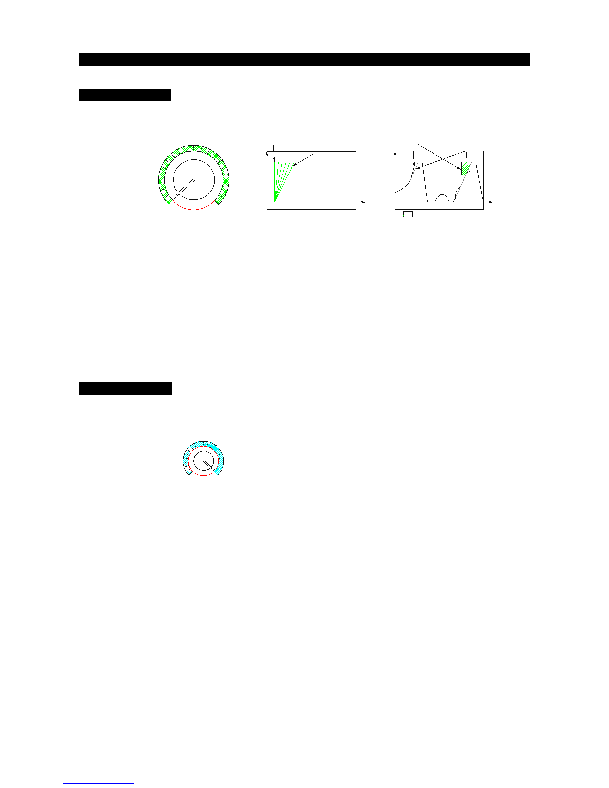
a word about the trigger readout
The SCP-1 rea s the trigger position from a magnet house in the trigger itself. The magnetic fiel
is rea by a Hall sensor, whose output is fe to the microcontroller (the CPU). The rea out is linear,
an there's a patent pen ing on a couple of technical aspects of this matter. What makes it
interesting for the user though, is that, being there no en of run switches or mechanical contacts,
there is no friction between the trigger an the cursor as in a tra itional controller, which means no
wearout, no ust, no change in characteristics.
The SCP-1 comprises a sophisticate software which can etect the en -of-run positions an self
calibrate uring normal operation. It comes precalibrate from factory so that it works as expecte
as soon as it is powere up.
19
0 1
0: brake OFF
1: brake ON

Version 1.1. of the controller (November 2010) a s an important new feature: it is now possible to
reprogram the factory-set base relationship, which links the phisical position of the magnet (trigger
position, in egrees) to the logical point on the mapping. In other wor s: un erneath all the curves
that you have rea so far, lays a base mapping through which the controller knows that a certain
rea out of the magnetic fiel correspon s to a certain position of the trigger. It is this 'base'
relationship which makes it possible, for the software, to create all the curves of the SCP-1. A small
change of the 'base' map, which normally is hi en from the user, can ra ically change the
behaviour of the controller. The base mapping is set uring pro uction, but a rewrite of the mapping
must be performe every time the trigger magnet is replace .
For the user, then, it is now possible to alter the base setting, as if you were using a completely
ifferent magnet.
Follow these steps to reprogram the base magnet-angle relationship:
1. unplug the controller, set the back switch CRV/LIN selector on CRV, an turn the blue
(CRV) potentiometer to '0' (completely ccw).
2. press all three buttons (arrow up, arrow own, roun buttons) an fully pull the trigger.
3. power the controller on (plug it in)
4. release trigger an buttons
5. all the LEDs shoul be ON now: green left, bicolor (re an green, which seems orange) on
the right. If this is not the case, repeat points from 1 to 4 until all LEDs are ON as
escribe . The reference points can be written if an only if all the LEDs are ON, which
means the controller is in 'learn' mo e:
6. 'zero' (min) point: leave the trigger completely unrelease , then press an release the roun
button: the green left LED light stays ON, the green light of the bicolor LED goes OFF, the
RED light of the bicolor LED stays ON:
7. '15°' point: press the trigger until the small plastic arrow in icating the angular position
reaches number '15' on the white scale. Keeping the trigger in this position, press an release
the roun button. The green left LED stays ON, green light of the bicolor LED turns ON,
the RED light of the bicolor LED goes OFF:
8. '25°' point: press the trigger until the small plastic arrow in icating the angular position
reaches number '25' on the white scale. Keeping the trigger in this position, press an release
the roun button. The green left LED turns, the green light of the bicolor LED stays ON:
9. 'Max' point: press the trigger fully. Keeping the trigger in this position, press an release the
roun button: the right RED LED will turn ON for 1”: , after which the green
LEDs will start blinking in icating that the programming is finishe : ↔
In order to readjust the base mapping or in case the magnet is replaced, this procedure must be
repeated. In particular: changing one of the middle points (15° and 25°) with a higher alue (for
example: 16° and 26°) during the steps 7 and 8 abo e generates a base mapping for a 'softer'
controller, whereas a shift in the opposite direction re erses the effect. Points '0' and 'Max' must (!)
be recorded only with the trigger completely released (0) and fully pressed (Max). Once this
programming technique is mastered, if so necessary your SCP-1 1.1. can be adjusted at will.
20
Table of contents


