SmartAV Smart Console E72 User manual

Smart Console™
Elite series
Installation Guide
For
Smart Console™ E72

2
2 E72 Smart Console™ Installation Guide March 2007
Index
Before you start opening boxes – Preparation 3
Furniture specification
Unpacking
3
5
Initial Assembly 5
Initial Connections 6
Physical Configuration Guide 7
Powering Up 9
Plate 1: Module bays 7
Plate 2: Rear of rack showing connection points 10
Plate 3: Rear left of console showing connection points 11
Plate 4: Rear of console showing Video conection points 11
Plate 4: E72 mounting points 12
Plate 6: Example angle bracket 12
Plate 7: E72 dimensions 13
Plate 8: Further E72 dimensions 14
Plate 9: Inserting modules 15
Plate 10: Inserting modules 2 16
16

3
E72 Smart Console™ Installation Guide Mar 2007 3
Congratulations! You have just purchased the world’s most ergonomically advanced
console. Your E72 Smart Console™ should provide you with many years of
trouble free operation, however it is important for you to properly install and
configure your console prior to operation.
This document contains instructions for assembly, connection and configuration of
your E72 Smart Console™. If you experience any problems or need any assistance
please contact your local distributor first or you can contact SmartAV technical
support in Australia via telephone on: +61 2 9648 6744 or via email on
Before you start opening boxes – Preparation
Let us go through what is needed before installation can be completed.
All the Elite series Smart Consoles™ are comprised of two parts: a control surface
(also referred to as ‘the console’) and a rack-mounted computer. A series of cables
connect these to each other. Ideally the rack-mounted computer will be located in
your machine room and four units of rack space should be allocated to it. From
there, a second Ethernet connection is required from the rack-mounted computer to
your mix engine or to the local area network (LAN) your mix engine is connected to.
Both the control surface and the rack-mounted computer will require mains power.
It will also be necessary to have a few helpers around for lifting, moving and
positioning the control surface part, as it is too large to be lifted by one person.
Please observe all safety and lifting precautions to prevent injuries.
Furniture specification:
The Smart Console™ Elite 72 (or E48) is designed to be dropped into a correctly
prepared unit of studio furniture. Refer to Plates 7 and 8 that detail the dimensions
of the cut-out required in your studio furniture. For stability, it is recommended that
the furniture feature a cross-beam below the console connecting the left and right
supporting legs.
The console itself is supported by three M6 screws which fit into mounting holes on
each side of the console. Refer to Plate 5.
The most desirable method of mounting is to attach an steel angle bracket of the
appropriate size via these mounting holes. This angle bracket is then mounted either
to the furniture itself or to a sub-frame within the furniture so that the top surface of
the furniture is flush with the top of the console surface. Refer to Plate 6 for an

4
4 E72 Smart Console™ Installation Guide March 2007
example of this type of construction method. In this case you may use the m6 screws
provided. In this case you MUST ensure that at least 15mm of the thread of each m6
screw is entirely within the console when fully mounted.
Alternatively the console may be attached to the furniture directly by passing screws
or bolts through the furniture into the console's mounting holes. In this case you
must source your own screws and you MUST ensure that at least 15mm (and no
more than 25mm) of the thread of each m6screw is entirely within the console when
fully mounted.
The console furniture should be rigid and should not rely on the console for its
structural integrity.
Note also that there will need to be sufficient clearance at the back of the console to
allow the rear bolster to be opened so that modules may be added and removed. The
clearance must also allow room for rear connecting cables and ventilation. See Plates
7 and 8 for exact measurements.
In the unlikely event of needing to service your console, you may also need to
remove the access panel in the rear of the console. This rear panel is held in place
with 10 screws that can be removed with a normal Phillips head screwdriver. Please
keep this in mind when designing your furniture.

5
E72 Smart Console™ Installation Guide Mar 2007 5
Unpacking
The following items should be included in your shipment:
•The control surface (unpopulated – that is without modules)
•Various modules depending on the particular console configuration ordered
•The rack computer
•The Arc™ Scribble Strip scanner
•A marker pen for the Scribble Strip
•An optional monitor arm
•Two power cables
•One five-metre network cable
•One shorter cross-over network cable
•One five-metre VGA cable
•One five-metre RCA cable
•Manuals
•Pre-installed Software (including backup disks of the Microsoft Windows XP
install disk, SmartAV install disk, and a drivers disk)
Initial Assembly
Firstly position the control surface in your studio furniture. Once the console has
been carefully lowered into the correctly sized space in your studio furniture, attach
the console using the three m6 screws on either side of the console . These screws
should pass through a weight bearing part of the furniture.
Next, ensure nothing inside the rack PC has been shaken loose by the vibration that
occurred during transit. To do this open the lid and check the seating of the PCI and
AGP cards, the RAM chips and the IDE cabling to the motherboard utilising all the
appropriate anti-static precautions.
Once you have done this reattach the lid and secure the rack computer into suitable
rack mountings in your machine room, ensuring there is adequate space for
ventilation and cooling.
Carefully unpack the modules, but at this stage resist the temptation to fit any of
them into the console.

6
6 E72 Smart Console™ Installation Guide March 2007
Initial Connections
Now that the control surface is securely positioned and the rack-mounted computer
is bolted into location it is time to start connecting the various cables.
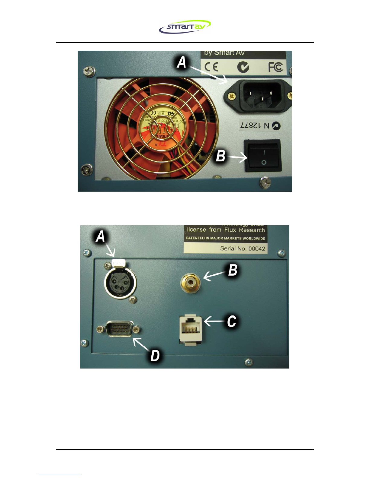
Begin with the mains power for each unit. The IEC socket is located on the left-hand
side of the back of the control surface if you are facing the back of the unit. Refer to
Pointer A on Plate 3. The rack PC is connected to mains power using the socket
indicated by Pointer B in Plate 2.
ENSURE MAINS POWER IS SWITCHED OFF AT THE SOCKET BEFORE CONNECTING
Next connect the supplied five-metre network cable to the socket on the Rack PC
marked by Pointer F in Plate 2. The other end should be connected to the rear of the
control surface (see Pointer D in Plate 4). Note there are two network sockets on the
rack and it is important to connect the correct one to the control surface.
If the supplied network cable is not long enough then ensure the cable used is a
Category 5 twisted-pair Ethernet cable suitable for 100 MB data speeds. It is
important that the console and the rack must be directly connected with a straight-
through type network cable and not connected via a LAN.
Now connect an Ethernet cable from the remaining network socket on the rack (see
Pointer C on Plate 2) to your mix engine or to your LAN where your mix engine is
also connected. If you connect directly between the rack and your mix engine you
will need to use the supplied crossover cable. A straight-through network cable
should be used if connecting the console to a LAN.
If your console includes a Scribble Strip Scanner, position the Scanner on the
Arc™. The Scanner has two spring-loaded wheels at the bottom and one at the top.
Position the bottom wheels against the black strip running along the lower edge of
the Arc™ and gently push the Scanner upwards while tilting the top of the
Scanner firmly downwards onto the Arc™. When the top wheel is aligned with the
black strip on the upper edge of the Arc™ there will be a click and the Scanner is
now in place. Connect the cable emerging from the Scanner to the console – the
socket for this is at the opposite end of the console to the power connection (see
Pointer A in Plate 4).
If your console includes a Scribble Strip Scanner there will be an RCA cable
supplied that needs to be connected between the console and the rack. Connect one
end of this RCA cable to the RCA socket on the rear of the console (see Pointer B in
Plate 4). Connect the other end of the RCA cable to the RCA socket marked ‘AV’ on
the back of your rack. Pointer E in Plate 2 indicates this socket.
7
E72 Smart Console™ Installation Guide Mar 2007 7
Now run the VGA cable from the VGA port on the control surface (indicated by
Pointer C on Plate 4) to the VGA input on the back of rack (indicated by Pointer D on
Plate 2).
Physical Configuration Guide
It is now time to start populating the console with the modules. However, let us first
look at the different types of modules and note the various legal positions they may
occupy in the console. With the exception of EQ and Fader modules, modules can
be identified by the name printed on the top-left or bottom-left corner.
Running horizontally through the middle of the chassis of every Smart Console™
Elite is a series of VFD display modules (also referred to as ‘Fader displays’ in Smart
Console user documentation) that separate the console into top and bottom halves.
Modules that are designed for the top half can never be positioned in the bottom half
and similarly modules for the lower part can never be fitted into the upper section.
Upper modules can be identified by their different profile and the fact that they are
longer than the lower modules.
All modules used with the Smart Console™ Elite are designed to fit vertically
aligned with either a VFD section with a display or a VFD section without a display,
depending on their function. For example, a Fader module can only be fitted below
a display section but not below a non-display section.
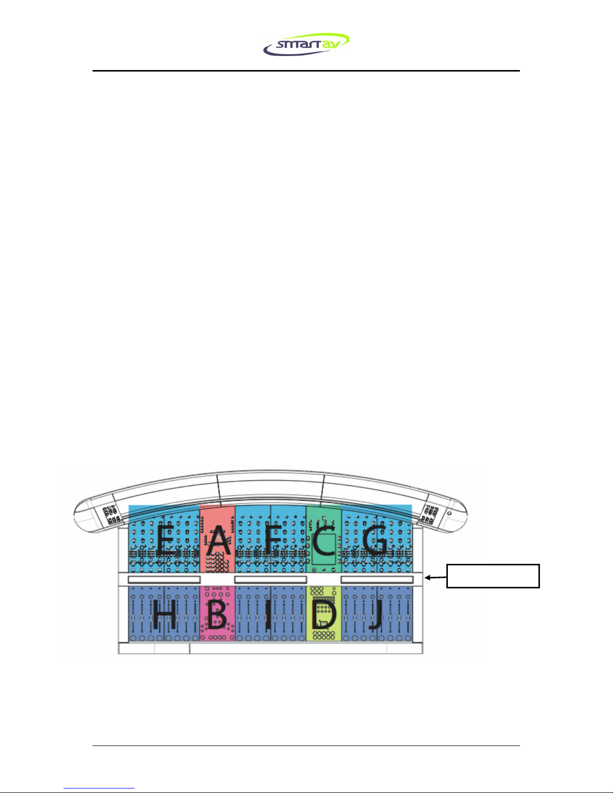
Every E72 has sixteen module bays, eight above the VFD modules and six below.
Plate 1: Module bays
VFD Displays

8
8 E72 Smart Console™ Installation Guide March 2007
Every console must have a Monitor Panel and an Expert Panel fitted as a pair
either in sections A and B or in sections C and D respectively as shown above.
Every console must also have an Upper Active Panel and a Lower Active Panel
also fitted as a pair in the remaining bays out of the A/B and C/D pairs.
Generally the upper and lower Active Panels are fitted to bays C and D, however
some users, such as left-handed engineers, may prefer them fitted in A and B. They
can of course be changed at will due to the hot-swappable nature of the console.
Now let us turn our attention to the bays denoted by E, F, G, H, I and J in the above
diagram. Two modules fit in the bays represented by each letter. The bays E, F and G
can either house a pair of EQ/AUX Modules or a double width module such as the
upper part of the Post Panel Module or a pair of blanking panels if this bay is
unused. EQ/AUX Modules and blanking panels can be mixed.
The bays H, I and J can either house a pair of blanking or Fader Modules or a
double width module such as the lower part of the Post Panel Module. The Post
Panel Module is an optional extra and not necessary for the operation of a console.
It is possible to fit a lower Post Panel Module without the upper module or vice
versa.
Similarly, the Fader Modules would ideally be fitted with EQ/AUX Modules
directly above them but the console will operate correctly if this is not the case.
Note that modules designed for bays A and C will not fit in bays E, F and G and vice
versa. Modules designed for bays B and D cannot be fitted in bays H, I and J.
Now it is time to begin populating the console with the modules. Insert the modules
one at a time, making sure to observe the legal positioning rules described above.
The technique for inserting a module is as follows:
Open the rear and front bolsters by grasping the ends of them and lifting them
upwards so they unlatch thus allowing them to swivel downwards and away from
the body of the console.
Each module has a handle-end and a connector-end. Position the module in the bay
so the connector-end slides in first while the handle-end is still raised slightly (see
Plate 9). Next lower the handle-end of the module so it is flush with the base of the
bay and, while keeping downward pressure on the connector-end, push the module
into place with the handle (see Plate 10). The modules will only click into place if the
switch under the handles is lifted. Once the module is seated make sure the switch is
pushed back down to ensure it is secured. Removing the modules is the reverse
procedure – lift the switch first before pulling out the module.
In the case that the console is not fully populated please install blanking-panels that
have been provided to complete the surface.

9
E72 Smart Console™ Installation Guide Mar 2007 9
Powering Up
The correct order for powering up the parts of your Smart Console™ for the first
time is as follows:
First, switch on the rack PC using the switch indicated by Pointer A in Plate 2. Then
power on the console via the switch indicated in Plate 3 by Pointer B. On the right-
hand end of the Arc™ press the silver start button. Each module correctly installed
in the console should shortly begin to flash the Light Emitting Diode (or LED) in the
upper left corner. The Arc™ should also flash the top-left-most LED (not including
meters) in both segments. If any modules do not flash their top-left-most LED then
re-seat them in the chassis of the console.
Next, the rack PC will automatically boot. Assuming all connections have been made
correctly then the control surface will go into its default state where all the top-left-
most LEDs will cease flashing. The screen on the Upper Active Panel should also
illuminate.
Congratulations! You are now ready to configure your mix engine to operate with
the Smart Console™. Please refer to the Engine Configuration Guide(s) relevant to
your audio engine(s) for further instructions.

10
10 E72 Smart Console™ Installation Guide March 2007
Plate 2: Rear of rack showing connection points.
11
E72 Smart Console™ Installation Guide Mar 2007 11
Plate 3: Rear left of E72 console showing connection points.
Plate 4: Rear of E72 console showing Scribble Strip™ Scanner connector (A), the
RCA cable connector (B), the Ethernet cable connector (C), and the SVGA connector
(D).

12
12 E72 Smart Console™ Installation Guide March 2007
Plate 5: E72 mounting points.
Plate 6: An example of the suggested angle bracket mounting procedure.
M6 mounting screws

13
E72 Smart Console™ Installation Guide Mar 2007 13
Plate 7: E72 dimensions.

14
14 E72 Smart Console™ Installation Guide March 2007
Plate 8: Further E72 dimensions.
Note: Threaded mounting posts are 6.5mm in diameter and 32mm long. Please leave
120mm clearance at rear of console for bolster to open, for ventilation and for rear
connecting cables.

15
E72 Smart Console™ Installation Guide Mar 2007 15
Plate 9: Inserting modules.
Plate 10: Inserting modules 2
Table of contents
Other SmartAV Music Mixer manuals


