Smartek UCC User manual

User
Manual
twentynine Camera Family
www.SMARTEK.vision ©SMARTEK d.o.o. 2017, information is subject to change without prior notice, Version 1.0.2 from 2017-07-03

For customers in Canada
This apparatus complies with the Class A limits for radio noise emissions set out in the Radio Interference
Regulations.
Pour utilisateurs au Canada
Cet appareil est conforme aux normes classe A pour bruits radioélectriques, spécifiées dans le Règlement
sur le brouillage radioélectrique.
Life support applications
These products are not designed for use in life support systems, appliances or devices where malfunction
of the products can reasonably be expected to result in personal injury. Customers, Integrators and End
Users using or selling these products for use in such applications do so at their own risk and agree to fully
indemnify SMARTEK d.o.o. for any damages resulting from any improper use or sale.
www.SMARTEK.vision ©SMARTEK d.o.o. 2017, information is subject to change without prior notice, Version 1.0.2 from 2017-07-03

Trademarks
All trademarks, trade names and products represented in this document, unless stated otherwise, are
brands protected internationally by law. No use of these may be made without prior, written authorization of
SMARTEK d.o.o except to identify the products or services of the company.
Warranty
SMARTEK d.o.o. has made reasonable efforts to ensure that the information provided in this document is
accurate at the time of inclusion. However there may be unintentional and occasional errors for which we
apologize. SMARTEK d.o.o. makes no representations, warranties or assurances of any kind as to the
accuracy, currency or completeness of the information provided. SMARTEK d.o.o. shall not be liable of any
damages or injury resulting from your reliance on any information provided in this document.
Copyright
All texts, pictures and graphics and intellectual property in this document are protected by copyright.
Reproduction of part or all of the content for trade or transfer purposes is prohibited. None of the content
of this document may be copied or otherwise incorporated into or stored in any other website, electronic
retrieval system, publication or other work in any form (whether hard copy, electronic or other). For the
avoidance of doubt, framing of this document or any part of it is not permitted without express permission.
www.SMARTEK.vision ©SMARTEK d.o.o. 2017, information is subject to change without prior notice, Version 1.0.2 from 2017-07-03

User Manual - twentynine
Contents
1 Platform Specification 1
1.1 twentynine Standard . . . . . . . . . . . . . . . . . . . . . . . . . . . . . . . . . . . . . . . . . . . 2
1.1.1 List of Specifications . . . . . . . . . . . . . . . . . . . . . . . . . . . . . . . . . . . . . . . 2
1.1.2 Technical Drawings . . . . . . . . . . . . . . . . . . . . . . . . . . . . . . . . . . . . . . . 3
1.2 Supported Industry Standards . . . . . . . . . . . . . . . . . . . . . . . . . . . . . . . . . . . . . 5
1.2.1 GigE Vision . . . . . . . . . . . . . . . . . . . . . . . . . . . . . . . . . . . . . . . . . . . . 5
1.2.2 USB3 Vision . . . . . . . . . . . . . . . . . . . . . . . . . . . . . . . . . . . . . . . . . . . 5
1.2.3 GenICam . . . . . . . . . . . . . . . . . . . . . . . . . . . . . . . . . . . . . . . . . . . . . 6
1.2.4 C-Mount . . . . . . . . . . . . . . . . . . . . . . . . . . . . . . . . . . . . . . . . . . . . . . 7
1.3 Supported Third-Party Software . . . . . . . . . . . . . . . . . . . . . . . . . . . . . . . . . . . . 7
1.4 IR-Cut Filter Specification . . . . . . . . . . . . . . . . . . . . . . . . . . . . . . . . . . . . . . . . 8
1.5 Precautions . . . . . . . . . . . . . . . . . . . . . . . . . . . . . . . . . . . . . . . . . . . . . . . . 9
1.6 EMI and ESD Consideration . . . . . . . . . . . . . . . . . . . . . . . . . . . . . . . . . . . . . . . 10
1.7 Temperature and Heat Dissipation . . . . . . . . . . . . . . . . . . . . . . . . . . . . . . . . . . . 11
1.8 Ingress Protection Class . . . . . . . . . . . . . . . . . . . . . . . . . . . . . . . . . . . . . . . . . 12
1.9 Declarations of Conformity . . . . . . . . . . . . . . . . . . . . . . . . . . . . . . . . . . . . . . . 13
1.9.1 CE . . . . . . . . . . . . . . . . . . . . . . . . . . . . . . . . . . . . . . . . . . . . . . . . . 13
1.9.2 RoHS II . . . . . . . . . . . . . . . . . . . . . . . . . . . . . . . . . . . . . . . . . . . . . . 14
2 Model Overview 15
2.1 GCC1931 / UCC1931 . . . . . . . . . . . . . . . . . . . . . . . . . . . . . . . . . . . . . . . . . . 15
2.2 GCC1932 / UCC1932 . . . . . . . . . . . . . . . . . . . . . . . . . . . . . . . . . . . . . . . . . . 17
2.3 GCC2061 / UCC2061 . . . . . . . . . . . . . . . . . . . . . . . . . . . . . . . . . . . . . . . . . . 19
2.4 GCC2062 / UCC2062 . . . . . . . . . . . . . . . . . . . . . . . . . . . . . . . . . . . . . . . . . . 21
2.5 GCC2461 / UCC2461 . . . . . . . . . . . . . . . . . . . . . . . . . . . . . . . . . . . . . . . . . . 23
2.6 GCC2462 / UCC2462 . . . . . . . . . . . . . . . . . . . . . . . . . . . . . . . . . . . . . . . . . . 25
3 Physical Interfaces 27
3.1 Gigabit Ethernet Interface (GCC) . . . . . . . . . . . . . . . . . . . . . . . . . . . . . . . . . . . . 28
3.1.1 Cabling Requirements . . . . . . . . . . . . . . . . . . . . . . . . . . . . . . . . . . . . . . 28
3.2 USB3.0 Interface (UCC) . . . . . . . . . . . . . . . . . . . . . . . . . . . . . . . . . . . . . . . . . 29
3.2.1 Cabling Requirements . . . . . . . . . . . . . . . . . . . . . . . . . . . . . . . . . . . . . . 29
3.3 Power and I/O Interface . . . . . . . . . . . . . . . . . . . . . . . . . . . . . . . . . . . . . . . . . 30
3.3.1 Cabling Requirements . . . . . . . . . . . . . . . . . . . . . . . . . . . . . . . . . . . . . . 31
3.3.2 Input Lines (Electrical Specification) . . . . . . . . . . . . . . . . . . . . . . . . . . . . . . 32
3.3.3 Output Lines (Electrical Specification) . . . . . . . . . . . . . . . . . . . . . . . . . . . . . 33
3.4 Status LED . . . . . . . . . . . . . . . . . . . . . . . . . . . . . . . . . . . . . . . . . . . . . . . . . 34
4 General Camera Architecture 35
4.1 CMOS Sensor Readout . . . . . . . . . . . . . . . . . . . . . . . . . . . . . . . . . . . . . . . . . 36
4.2 Color Imaging with Bayer Pattern . . . . . . . . . . . . . . . . . . . . . . . . . . . . . . . . . . . . 37
4.3 Shutter Types and Frame Readout . . . . . . . . . . . . . . . . . . . . . . . . . . . . . . . . . . . 39
4.3.1 Global Shutter Readout . . . . . . . . . . . . . . . . . . . . . . . . . . . . . . . . . . . . . 39
4.3.2 Electronic Rolling Shutter (ERS) Readout . . . . . . . . . . . . . . . . . . . . . . . . . . 40
4.3.2.1 Eliminating Rolling Shutter Effects . . . . . . . . . . . . . . . . . . . . . . . . . 40
4.3.3 Global Reset Release (GRR) Readout . . . . . . . . . . . . . . . . . . . . . . . . . . . . 42
ISMARTEK Vision | User Manual - twentynine | Doc. v1.0.2

User Manual - twentynine
5 Camera Features 43
5.1 List of Supported Features . . . . . . . . . . . . . . . . . . . . . . . . . . . . . . . . . . . . . . . 43
5.2 Brightness and Sensor Signal Control . . . . . . . . . . . . . . . . . . . . . . . . . . . . . . . . . 45
5.2.1 Exposure / Integration Time . . . . . . . . . . . . . . . . . . . . . . . . . . . . . . . . . . . 45
5.2.2 Analog Gain and Black Level . . . . . . . . . . . . . . . . . . . . . . . . . . . . . . . . . . 47
5.2.2.1 Analog Gain . . . . . . . . . . . . . . . . . . . . . . . . . . . . . . . . . . . . . . 47
5.2.2.2 Black Level . . . . . . . . . . . . . . . . . . . . . . . . . . . . . . . . . . . . . . . 49
5.2.3 Automatic Exposure and Gain Control . . . . . . . . . . . . . . . . . . . . . . . . . . . . 50
5.2.4 Digital Shift . . . . . . . . . . . . . . . . . . . . . . . . . . . . . . . . . . . . . . . . . . . . 51
5.2.5 Gamma Adjustment . . . . . . . . . . . . . . . . . . . . . . . . . . . . . . . . . . . . . . . 52
5.2.6 Luminance Look-up-Table . . . . . . . . . . . . . . . . . . . . . . . . . . . . . . . . . . . . 53
5.3 Region of Interest (ROI) . . . . . . . . . . . . . . . . . . . . . . . . . . . . . . . . . . . . . . . . . 55
5.3.1 Multiple Regions of Interest . . . . . . . . . . . . . . . . . . . . . . . . . . . . . . . . . . . 56
5.3.2 Region of Interest Centering . . . . . . . . . . . . . . . . . . . . . . . . . . . . . . . . . . 58
5.4 Acquisition Control . . . . . . . . . . . . . . . . . . . . . . . . . . . . . . . . . . . . . . . . . . . . 59
5.4.1 Image Acquisition Features . . . . . . . . . . . . . . . . . . . . . . . . . . . . . . . . . . . 59
5.4.1.1 Acquisition Mode . . . . . . . . . . . . . . . . . . . . . . . . . . . . . . . . . . . 60
5.4.1.2 Acquisition Frame Rate . . . . . . . . . . . . . . . . . . . . . . . . . . . . . . . . 60
5.4.2 Trigger Features . . . . . . . . . . . . . . . . . . . . . . . . . . . . . . . . . . . . . . . . . 60
5.4.2.1 Trigger Selector . . . . . . . . . . . . . . . . . . . . . . . . . . . . . . . . . . . . 60
5.4.2.2 Trigger Mode . . . . . . . . . . . . . . . . . . . . . . . . . . . . . . . . . . . . . . 61
5.4.2.3 Trigger Source . . . . . . . . . . . . . . . . . . . . . . . . . . . . . . . . . . . . . 61
5.4.2.4 Trigger Activation . . . . . . . . . . . . . . . . . . . . . . . . . . . . . . . . . . . 61
5.4.2.5 Trigger Delay . . . . . . . . . . . . . . . . . . . . . . . . . . . . . . . . . . . . . . 62
5.4.3 Free Run Operation . . . . . . . . . . . . . . . . . . . . . . . . . . . . . . . . . . . . . . . 62
5.5 Digital Input / Output Control . . . . . . . . . . . . . . . . . . . . . . . . . . . . . . . . . . . . . . 63
5.5.1 Input Lines . . . . . . . . . . . . . . . . . . . . . . . . . . . . . . . . . . . . . . . . . . . . 63
5.5.1.1 Line Debouncer . . . . . . . . . . . . . . . . . . . . . . . . . . . . . . . . . . . . 65
5.5.2 Output Lines . . . . . . . . . . . . . . . . . . . . . . . . . . . . . . . . . . . . . . . . . . . 66
5.6 GigE Vision Specific Features . . . . . . . . . . . . . . . . . . . . . . . . . . . . . . . . . . . . . . 67
5.6.1 UDP Packet Resend Mechanism . . . . . . . . . . . . . . . . . . . . . . . . . . . . . . . . 67
5.6.2 Inter-Packet Delay . . . . . . . . . . . . . . . . . . . . . . . . . . . . . . . . . . . . . . . . 71
5.6.2.1 Setting Inter Packet Delay . . . . . . . . . . . . . . . . . . . . . . . . . . . . . . 72
5.6.3 Frame Transfer Delay . . . . . . . . . . . . . . . . . . . . . . . . . . . . . . . . . . . . . . 73
5.6.3.1 Setting Frame Transfer Delay . . . . . . . . . . . . . . . . . . . . . . . . . . . . 74
5.7 Digital Image and Pixel Formats . . . . . . . . . . . . . . . . . . . . . . . . . . . . . . . . . . . . 75
5.7.1 Image Layout . . . . . . . . . . . . . . . . . . . . . . . . . . . . . . . . . . . . . . . . . . . 75
5.7.2 Mono8 . . . . . . . . . . . . . . . . . . . . . . . . . . . . . . . . . . . . . . . . . . . . . . . 76
5.7.3 Mono10Packed . . . . . . . . . . . . . . . . . . . . . . . . . . . . . . . . . . . . . . . . . . 76
5.7.4 Mono12Packed . . . . . . . . . . . . . . . . . . . . . . . . . . . . . . . . . . . . . . . . . . 77
5.7.5 Mono16 . . . . . . . . . . . . . . . . . . . . . . . . . . . . . . . . . . . . . . . . . . . . . . 77
5.7.6 BayerGR8 / BayerRG8 / BayerGB8 / BayerBG8 . . . . . . . . . . . . . . . . . . . . . . . 78
5.7.7 BayerGR16 / BayerRG16 / BayerGB16 / BayerBG16 . . . . . . . . . . . . . . . . . . . . 79
6 CameraSuite SDK 80
6.1 Supported Operating Systems . . . . . . . . . . . . . . . . . . . . . . . . . . . . . . . . . . . . . 80
6.2 Installation of the CameraSuite SDK . . . . . . . . . . . . . . . . . . . . . . . . . . . . . . . . . . 81
6.3 Manual Driver Installation . . . . . . . . . . . . . . . . . . . . . . . . . . . . . . . . . . . . . . . . 82
6.3.1 Installation GigE Vision Filter Driver . . . . . . . . . . . . . . . . . . . . . . . . . . . . . 82
6.3.2 Installation USB3 Vision Device Driver . . . . . . . . . . . . . . . . . . . . . . . . . . . . 82
II SMARTEK Vision | User Manual - twentynine | Doc. v1.0.2

User Manual - twentynine
6.4 Unattended SDK Installation (Microsoft Windows) . . . . . . . . . . . . . . . . . . . . . . . . . . 83
6.5 CameraSuiteClient . . . . . . . . . . . . . . . . . . . . . . . . . . . . . . . . . . . . . . . . . . . . 83
6.5.1 Graphical User Interface (GUI) . . . . . . . . . . . . . . . . . . . . . . . . . . . . . . . . . 84
6.5.2 Acquire Images from Camera(s) . . . . . . . . . . . . . . . . . . . . . . . . . . . . . . . . 86
6.5.2.1 Device Enumeration . . . . . . . . . . . . . . . . . . . . . . . . . . . . . . . . . 86
6.5.2.2 Device IP Setup . . . . . . . . . . . . . . . . . . . . . . . . . . . . . . . . . . . . 88
6.5.2.3 Device Properties . . . . . . . . . . . . . . . . . . . . . . . . . . . . . . . . . . . 90
6.5.2.4 Multiple Devices, Multiple Views . . . . . . . . . . . . . . . . . . . . . . . . . . 92
6.5.2.5 Image Processing . . . . . . . . . . . . . . . . . . . . . . . . . . . . . . . . . . . 93
6.5.3 API Settings Dialog . . . . . . . . . . . . . . . . . . . . . . . . . . . . . . . . . . . . . . . 94
6.5.4 Chunk Data Control . . . . . . . . . . . . . . . . . . . . . . . . . . . . . . . . . . . . . . . 95
6.5.5 Log Dialog . . . . . . . . . . . . . . . . . . . . . . . . . . . . . . . . . . . . . . . . . . . . . 96
6.5.6 Firmware Update . . . . . . . . . . . . . . . . . . . . . . . . . . . . . . . . . . . . . . . . . 97
7 GigE Vision / USB3 Vision Specific Notes 98
7.1 GigE Vision . . . . . . . . . . . . . . . . . . . . . . . . . . . . . . . . . . . . . . . . . . . . . . . . 98
7.1.1 Choosing the right Network Interface Card (NIC) . . . . . . . . . . . . . . . . . . . . . . 98
7.1.2 LAN IP Configuration . . . . . . . . . . . . . . . . . . . . . . . . . . . . . . . . . . . . . . 99
7.1.2.1 IP Setup in Microsoft Windows . . . . . . . . . . . . . . . . . . . . . . . . . . . 99
7.1.3 Network Interface Optimization . . . . . . . . . . . . . . . . . . . . . . . . . . . . . . . . . 100
7.1.3.1 Jumbo Frames - Network Interface Cards . . . . . . . . . . . . . . . . . . . . . 100
7.1.3.2 Jumbo Frames - Gigabit Ethernet Switches . . . . . . . . . . . . . . . . . . . . 101
7.1.3.3 Raising Receive Buffers . . . . . . . . . . . . . . . . . . . . . . . . . . . . . . . 102
7.1.3.4 Disable the Interrupt Moderation Rate . . . . . . . . . . . . . . . . . . . . . . . 103
7.1.3.5 Disable the Flow Control . . . . . . . . . . . . . . . . . . . . . . . . . . . . . . . 104
7.2 USB3 Vision . . . . . . . . . . . . . . . . . . . . . . . . . . . . . . . . . . . . . . . . . . . . . . . . 105
7.2.1 Choosing the right USB3.0 Host Controller . . . . . . . . . . . . . . . . . . . . . . . . . . 105
7.2.2 USB 3.0 Cabling Recommendation . . . . . . . . . . . . . . . . . . . . . . . . . . . . . . 105
8 Image Processing in CameraSuite SDK 106
8.1 Image Statistics . . . . . . . . . . . . . . . . . . . . . . . . . . . . . . . . . . . . . . . . . . . . . . 107
8.1.1 Histogram . . . . . . . . . . . . . . . . . . . . . . . . . . . . . . . . . . . . . . . . . . . . . 107
8.1.2 Average Luminance Calculation . . . . . . . . . . . . . . . . . . . . . . . . . . . . . . . . 111
8.2 Image Processing Algorithms . . . . . . . . . . . . . . . . . . . . . . . . . . . . . . . . . . . . . . 113
8.2.1 Luminance Look-Up Table (LUT) . . . . . . . . . . . . . . . . . . . . . . . . . . . . . . . . 113
8.2.2 Digital Gain . . . . . . . . . . . . . . . . . . . . . . . . . . . . . . . . . . . . . . . . . . . . 119
8.2.3 Auto Exposure and Auto Gain . . . . . . . . . . . . . . . . . . . . . . . . . . . . . . . . . 122
8.2.4 White Balance . . . . . . . . . . . . . . . . . . . . . . . . . . . . . . . . . . . . . . . . . . 124
8.2.5 Gamma Correction . . . . . . . . . . . . . . . . . . . . . . . . . . . . . . . . . . . . . . . . 127
8.2.6 Color Filter Array Interpolation (Demosaicing / Debayering) . . . . . . . . . . . . . . . . 130
8.2.7 Matrix Multiplication 3x3 . . . . . . . . . . . . . . . . . . . . . . . . . . . . . . . . . . . . . 134
8.2.8 GIMP HSL . . . . . . . . . . . . . . . . . . . . . . . . . . . . . . . . . . . . . . . . . . . . . 136
8.2.9 Sharpening . . . . . . . . . . . . . . . . . . . . . . . . . . . . . . . . . . . . . . . . . . . . 139
8.2.10 RGB to Grayscale Conversion . . . . . . . . . . . . . . . . . . . . . . . . . . . . . . . . . 141
8.2.11 Bit Depth Conversion . . . . . . . . . . . . . . . . . . . . . . . . . . . . . . . . . . . . . . 143
8.2.12 Flip / Rotate Transformation . . . . . . . . . . . . . . . . . . . . . . . . . . . . . . . . . . . 144
8.3 Color Image Processing Pipeline . . . . . . . . . . . . . . . . . . . . . . . . . . . . . . . . . . . . 146
9 Revision History 147
10 Contact Information 148
III SMARTEK Vision | User Manual - twentynine | Doc. v1.0.2

User Manual - twentynine
1 Platform Specification
The SMARTEK Vision twentynine camera family offers an affordable and easy to use set of digital cameras
designed to meet demanding high quality machine vision applications, conforming to the industrial GigE
Vision and USB3 Vision standard. The compact housing fits almost every space critical application.
Focusing on a wide selection of SONY and ON Semiconductor CMOS sensors, the twentynine platform
delivers images with high sensitivity and low noise on a broad range of image resolutions at high framerates.
Excellent price to performance ratio makes this portfolio the perfect choice for every demanding user.
SMARTEK Vision twentynine cameras combine standard Gigabit Ethernet and USB3.0 technology
with the CameraSuite image acquisition software to reliably capture and transfer images from the camera
to the PC. All twentynine cameras are supported by one Software Development Kit as well as a large
number of 3rd-party libraries compliant to the GigE Vision and USB3 Vision standards. To use our devices
with other software than provided by SMARTEK Vision, please check the documentation of your 3rd-party
provider.
Key benefits & features:
•Powerful hardware in miniature 29x29 mm
footprint
•Latest CMOS Global Shutter sensors with
SONY Pregius series
•Resolutions from 2.3MP up to 5MP on
standard C-Mount
•Fully GigE Vision and USB3 Vision compliant:
–High data rates and plug & play
–Long cable length up to 100 m
(GigE Vision)
•Opto-isolated input and output
•Standard C-Mount lens adapter
•Low power consumption
•Enhanced set of supported features:
–Automatic Exposure / Gain Control
–Multiple Area of Interest Support
–Gamma Control
–10-/12-Bit Lookup-Table
–Chunk Data Control
•Affordable cabling and industrial connectors:
–EIAJ (Hirose) 6 pin and screw mount
RJ45 / USB3.0 Micro-B
•Comprehensive SDK for Windows and Linux,
supporting C, C++, .NET and Delphi
•Flexible customization concept
•3 years warranty
1SMARTEK Vision | User Manual - twentynine | Doc. v1.0.2
User Manual - twentynine
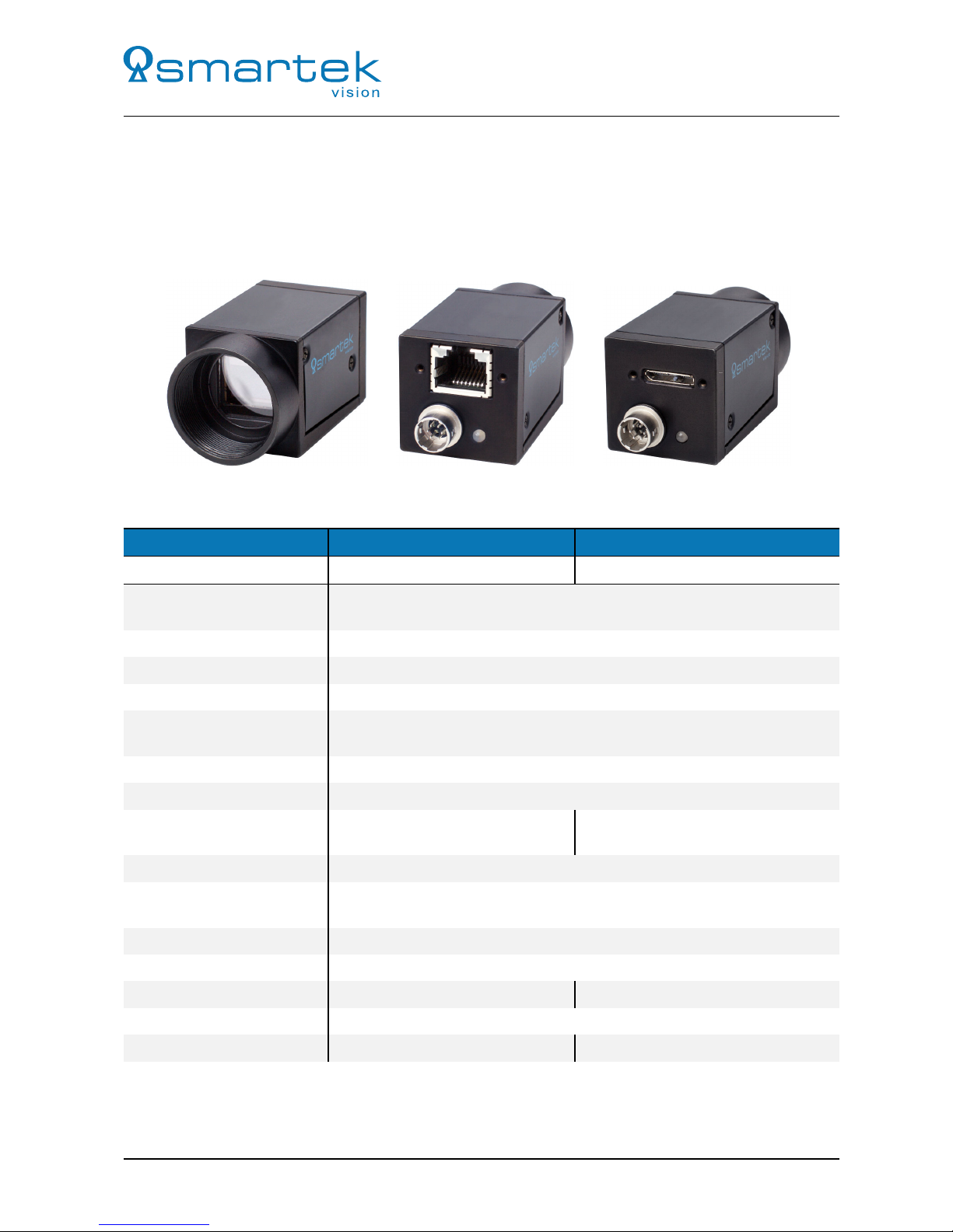
1.1 twentynine Standard
The twentynine camera series with standard housing represents the regular camera design for the xCC
series, with the main focus on a small form factor, offering the comprehensive camera electronics in a small
29x29x43 mm footprint. Table 1 contains an overview about the model specific specifications.
1.1.1 List of Specifications
GCC UCC
Data Interface GigE Vision USB3 Vision
External dimensions
(H x W x L) 29 x 29 x 43 [mm]
Housing Black anodized aluminum case
Weight Approx. 90g
Storage temperature -30◦C to +60◦C
Operating housing
temperature 0◦C to +50◦C
Operating humidity 20% to 80%, relative, non-condensing
Storage humidity 20% to 80%, relative, non-condensing
Power requirement 10V to 24V DC or
Power over Ethernet (PoE) Via USB3.0 interface
Lens mount C-Mount
Connectors Screw mount Ethernet RJ45 (Communication and Data),
Circular Hirose 6 pin (Power and I/O-Interface)
Digital input 1 input channel, opto-isolated
Digital output 1 output channel, opto-isolated
Data/Control Interface 1GBase-T / 100Base-T (RJ45) USB3.0 (Micro-B)
Conformity1 CE, RoHS II, GenICam
Conformity2 GigE Vision, PoE (IEEE802.3af) USB3 Vision
Table 1: Mechanical and electrical specifications
2SMARTEK Vision | User Manual - twentynine | Doc. v1.0.2

User Manual - twentynine
1.1.2 Technical Drawings
0,7920
1,14
29
1,1429 2x M 2,0
0,47
12
0,79
20
1,48
37,50
0,5413,80
0,6015,30
2x M 2,03x M 3,0
1,14
29
1,1429 C-Mount andimage sensor
optical center
1,10
27,86
2,1253,80 1,6943
0,276,80
A
Figure 1: Technical measures of the GCC camera housing (all dimensions are in mm [inch])
3SMARTEK Vision | User Manual - twentynine | Doc. v1.0.2

User Manual - twentynine
1,14
29
1,14
29
0,71
18
2x M 2,0
1,48
37,50
0,54
13,80
0,60
15,30
0,47
12
0,79
20
2x M 2,0
3x M 3,0
1,14
29
1,14
29
C-Mount and
image sensor
optical center
1,10
27,86
2,12
53,80
1,69
43
0,27
6,80
Figure 2: Technical measures of the UCC camera housing (all dimensions are in mm [inch])
4SMARTEK Vision | User Manual - twentynine | Doc. v1.0.2

User Manual - twentynine
1.2 Supported Industry Standards
1.2.1 GigE Vision
GigE Vision is a communication interface standard for high-performance
industrial cameras based on the Gigabit Ethernet technology. The main idea
driving the development of the standard is to unify different protocols used in
machine vision industrial applications and make hardware and software from various vendors interoperate
seamlessly over GigE connections. GigE Vision is administrated by the Automated Imaging Association
(AIA).
Features of the GigE Vision standard:
•Fast data transfer rates - up to 1 Gbit/s (based on 1000BASE-T)
•Data transfer length up to 100m exceeding maximum length of FireWire, USB and Camera Link
interfaces.
•Based on established standard allowing communication with other Ethernet devices and computers.
•Uses GenICam™generic programming interface
GigE Vision has four main elements:
•GigE Vision Control Protocol (GVCP) - runs on the UDP protocol. The standard defines how an
application controls and configures devices, and instantiates stream channels on the device. It also
defines the way for the device to notify an application about specific events.
•GigE Vision Stream Protocol (GVSP) - covers the definition of data types and the ways images and
other data are transferred from device to application.
•GigE Device Discovery Mechanism - provides mechanisms for a device to obtain valid IP address and
for an application to enumerate devices on the network.
•XML description - file based on the GenICam standard which provides the mapping between a device
feature and the device register implementing the feature.
1.2.2 USB3 Vision
USB3 Vision is a communication interface standard for high-bandwidth
industrial cameras based on the USB3.0 interface. Similar to the GigE
Vision standard it unifies different protocols used in machine vision industrial
applications and makes hardware and software from various vendors interoperate seamlessly over a USB3.0
connection. USB3 Vision is administrated by the Automated Imaging Association (AIA).
Features of the USB3 Vision standard:
•Very-high data transfer rates - up to 350 MB/s
•Plug-and-play interface for easy use
•Uses GenICam™generic programming interface
•Based on established standard USB3.0
5SMARTEK Vision | User Manual - twentynine | Doc. v1.0.2

User Manual - twentynine
1.2.3 GenICam
GenICam (Generic Interface for Cameras) is a generic
programming interface for machine vision cameras. The
goal of the standard is to decouple industrial camera
interface technology (such as GigE Vision, Camera Link,
USB or FireWire) from the user application programming interface (API). GenICam is administered by the
European Machine Vision Association (EMVA).
GenICam consists of three modules to help solve the main tasks in machine vision field in a generic
way. These modules are:
•GenApi - configures the camera and details how to access and control cameras by using an XML
description file.
•Standard Feature Naming Convention (SFNC) - are the recommended names and types for common
features in cameras to promote interoperability
•GenTL - is the transport layer interface for enumerating cameras, grabbing images from the camera,
and moving them to the user application.
GenICam provides supports for five basic functions:
•Configuring the camera - supports a range of camera features such as frame size, acquisition speed,
pixel format, gain, image offset, etc.
•Grabbing images - creates access channels between the camera and the user interface and initiates
receiving images.
•Graphical user interface - enables user GUI interface to seamlessly talk to the camera(s).
•Transmitting extra data - enables cameras to send extra data on top of the image data. Typical
examples could be histogram information, time stamp, area of interest in the frame, etc.
•Delivering events - enables cameras to talk to the application through an event channel
Standard Features Naming Convention (SFNC)
SFNC provides the definitions of standard use cases and standard features. The goal is to cover and to
standardize the naming convention used in all those basic use cases where the implementation by different
vendors would be very similar anyway. The GenICam technology allows exposing arbitrary features of a
camera through a unified API and GUI. Each feature can be defined in an abstract manner by its name,
interface type, unit of measurement and behavior. The GenApi module of the GenICam standard defines
how to write a camera description file that describes a specific camera’s mapping.
For detailed information about this convention visit www.emva.org.
6SMARTEK Vision | User Manual - twentynine | Doc. v1.0.2

User Manual - twentynine
1.2.4 C-Mount
AC-Mount is a type of lens mount commonly found on 16mm movie cameras, closed-circuit television
cameras (CCTV), trinocular microscope photo tubes and CCD/CMOS digital cameras. C-Mount lenses
provide a male thread which mates with a female thread on the camera. The thread is nominally 25.4mm
[1"] in diameter, with 32 threads per inch, designated as ”1-32 UN 2A” in the ANSI B1.1 standard for unified
screw threads. The flange focal distance is 17.526mm [0.69"] and thread length 3.8mm [0.15"].
1.3 Supported Third-Party Software
The twentynine cameras have been verified to be applicable with the third-party software shown below in
Table 2.
Software Requirements
Cognex Vision Pro Native (GigEVision interface)
Matrox Imaging Library Native (GigEVision interface)
MVTec Halcon Native (GigEVision interface)
National Instruments
LabView National Instruments IMAQdx (Plugin)
Scorpion Vision Plugin provided by SMARTEK Vision
Table 2: Third-Party Software
7SMARTEK Vision | User Manual - twentynine | Doc. v1.0.2

User Manual - twentynine
1.4 IR-Cut Filter Specification
The spectral sensitivity of the CMOS image sensors extends into the near-infrared range, what can result
in for the human eye unnatural-looking images on color camera models. To allow an accurate reproduction
of images from color image sensors, IR-cut filters are used.
IR-cut filters are short pass filters that block near infrared light of wavelengths longer than approximately
660nm and pass visible light. All color camera models are equipped with an IR-cut filter as standard,
monochrome models do not have an IR-cut filter installed by default. Figure 3 below shows the transmission
curve of the filter used in the twentynine camera family.
0
10
20
30
40
50
60
70
80
90
100
400 500 600 700 800 900 1000
Transmission [%]
Wavelength (nm)
Figure 3: IR-cut filter specification
8SMARTEK Vision | User Manual - twentynine | Doc. v1.0.2

User Manual - twentynine
1.5 Precautions
Due to the ultra-small compact housing of the camera, it has a tendency to develop a high
temperature. To maintain an optimal working temperature, mount the camera on a metal surface.
Do not attempt to disassemble this camera, there are sensitive optical parts inside. Tampering
with it could lead to permanent damage.
Do not expose this camera to rain or moisture. This device is not intended to work under wet
conditions.
Do not face this camera towards the sun, extremely bright light or light reflecting objects. Even
when the camera is not in use, put the supplied lens cap on the lens mount, to prevent damage
to the sensor.
Handle this camera with the maximum care. Do not throw the device; there are fragile glass parts
inside.
Operate this cameras only with the type of power source that meets the specifications indicated
on the camera and within the documentation. Operating the camera outside of the specifications
can cause to permanent damage.
9SMARTEK Vision | User Manual - twentynine | Doc. v1.0.2

User Manual - twentynine
1.6 EMI and ESD Consideration
Excessive EMI and ESD can cause problems with your camera such as false triggering or can cause the
camera to suddenly stop capturing images. EMI and ESD can also have a negative impact on the quality of
the image data transmitted by the camera.
To avoid problems with EMI and ESD, you should follow these general guidelines:
•Use high quality shielded cables. The use of high quality cables is one of the best defenses against
EMI and ESD.
•Try to use camera cables with correct length and try to run the camera cables and power cables
parallel to each other. Avoid coiling camera cables.
•Avoid placing camera cables parallel to wires carrying high-current, switching voltages such as wires
supplying stepper motors or electrical devices that employ switching technology.
•Attempt to connect all grounds to a single point, e.g. use a single power outlet for the entire system
and connect all grounds to the single outlet.
•Use a line filter on the main power supply.
•Install the camera and camera cables as far as possible from devices generating sparks.
•Decrease the risk of electrostatic discharge by taking the following measures:
•Use conductive materials at the point of installation.
•Use suitable clothing (cotton) and shoes.
•Control the humidity in your environment. Low humidity can cause ESD problems.
10 SMARTEK Vision | User Manual - twentynine | Doc. v1.0.2
User Manual - twentynine
1.7 Temperature and Heat Dissipation
The temperature specification given for storing and operation of all devices are measured at any location of
the camera’s housing. If the camera is delivered without a housing, the specified range refers to the direct
ambient temperature of the board-set, at any location. In operation it must be ensured that the internal
heat generation of the camera is dissipated sufficiently to make the device or its environment not exceed
the specified borders. The camera will steadily heat up in the first hour of operation and should be monitored.
Beside the risk of damage, a too high camera temperature also decreases the image quality of the
sensor significantly. The thermal noise generated in silicon based sensors raises exponentially with the
temperature, hereby the useful signal falls rapidly.
As every application and environment has its own characteristics, SMARTEK Vision can only suggest
general strategies to keep the camera’s temperature low:
•Mount housed cameras with at least one complete side of the housing to a massive heat conductive
material (e.g. aluminum); make sure that the whole surface is constantly in touch
•Active cooling of the camera by a fan will significantly decrease the temperature
•Keep the ambience temperature as low as possible
Board level cameras:
•If mounted into another closed device, make sure to offer a constant heat exchange by e.g. an air flow
•Additional active / passive heat sinking of the critical components (Sensor Head, Flash, FPGA, DDR,
Ethernet Physical, PoE driver etc.) allows for higher ambient temperatures (at own risk)
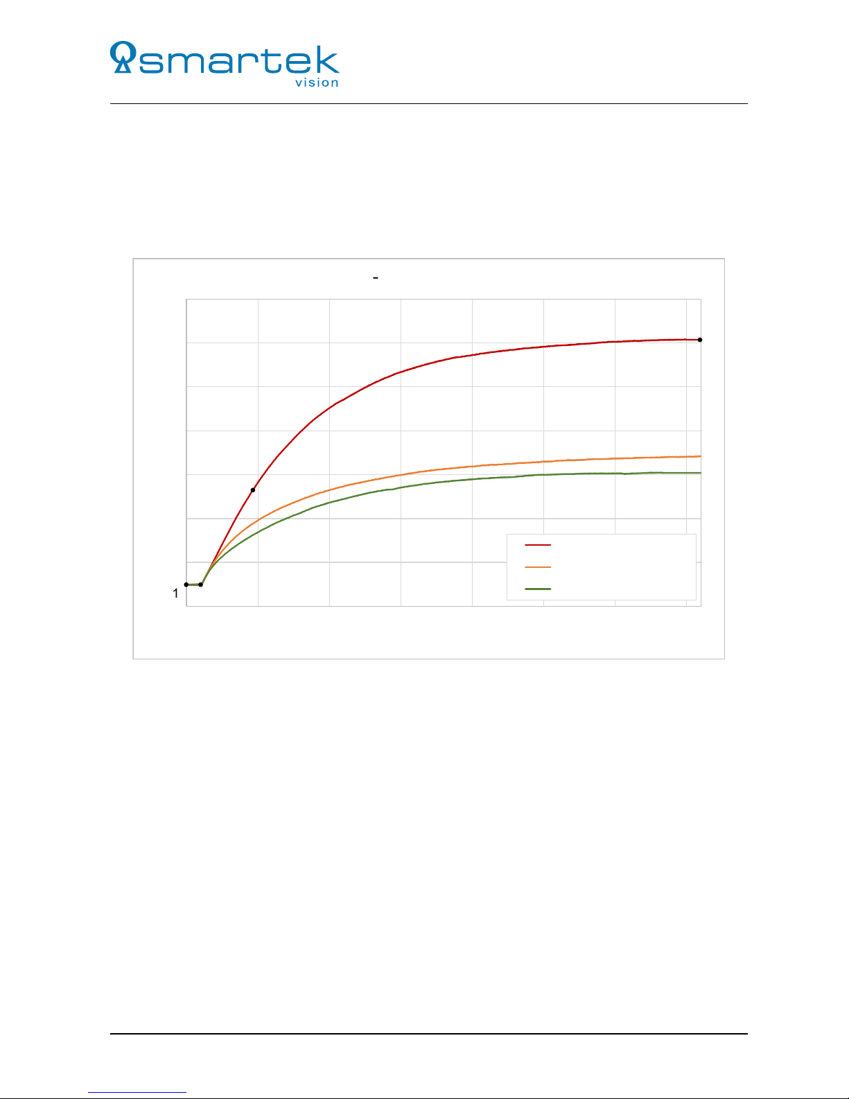
Example
Figure 4 gives an example of the thermal behavior of a twentynine camera mounted to different heat
conductors, described in Table 3. The used camera is a GCC1932M with IMX249 CMOS Imaging sensor,
which was chosen as one with typical power consumption (3.2 Watts) in the twentynine lineup.
Color Label Description
—- Not mounted Camera is placed on a material with a very low heat
conductivity (plastic); the main heat dissipation occurs over
the surrounding air
—- Aluminum (loose) Camera is placed loose on a construction profile (150x70x30
mm) of a material with a very good heat conductivity
(aluminum)
—- Aluminum (well mounted) Camera is well mounted on a construction profile (150x70x30
mm) of a material with a very good heat conductivity
(aluminum)
Table 3: Description of the curves in Figure 4
11 SMARTEK Vision | User Manual - twentynine | Doc. v1.0.2
User Manual - twentynine
In each setup, the camera and its heat conductor are exposed to the environment temperature of 22.5◦C,
until all match (1). As soon as the camera is powered (2) it starts to heat immediately (3) and reaches its
maximum after around one hour (4). The difference in temperature between the sample setups is significant;
the camera which is not mounted to any heat conductor shows after one hour in an environment with 22.5◦C
a device temperature of 50.4◦C. With a small aluminum heat conductor the camera temperature drops about
12◦C to 15◦C, depending on the connection to the heat sink.
20
25
30
35
40
45
50
55
0
500
1000
1500
2000
2500
3000
3500
Temperature (in
°
C)
Time (in s)
Heat
-
Up Graphs (GCC1932C)
Not mounted
Aluminum (loose)
Aluminum (well mounted)
(
1
)
(
2
)
(
3
)
(
4
)
Figure 4: Example of heating behavior of a camera with different thermal connections
1.8 Ingress Protection Class
The camera housing fulfills the Ingress Protection Class of IP40. It is protected against solid objects with a
diameter larger than 1 mm (tools, wires, and small wires) and has no protection against liquids.
12 SMARTEK Vision | User Manual - twentynine | Doc. v1.0.2

User Manual - twentynine
1.9 Declarations of Conformity
1.9.1 CE
Manufacturer: Smartek d.o.o
Dobrise Cesarica 5
HR-40000 Cakovec
Croatia
Product: GCC Digital Gigabit Ethernet Camera
UCC Digital USB Camera
Type Family: twentynine GigE
twentynine USB
Type of Equipment: GCC1931C, GCC1931M, GCC1932C, GCC1932M, GCC2061C,
GCC2061M, GCC2062C, GCC2062M, GCC2461C, GCC2461M,
GCC2462C, GCC2462M, UCC1931C, UCC1931M UCC1932C,
UCC1932M, UCC2061C, UCC2061M, UCC2062C, UCC2062M,
UCC2461C, UCC2461M, UCC2462C, UCC2462M.
This equipment is in compliance with the essential requirements and other relevant provisions of the
following EC directives:
Reference No. Title:
2014/30/EU Electromagnetic Compatibility (EMC directive)
Following standards or normative documents:
EN 61000-6-3:2007 + A1:2011
EN 61000-6-2:2005
Certificates / Test reports:
C251-0072/17 / T251-0272/17
C251-0071/17 / T251-0275/17
The equipment specified above was tested conforming to the applicable Rules under the most accurate
measurement standards possible, and that all the necessary steps have been taken and are in force to
assure that production units of the same product will continue comply with the requirements.
Damir
Dolar
CEO
Smartek
d
.
o
.
o
.
13 SMARTEK Vision | User Manual - twentynine | Doc. v1.0.2

User Manual - twentynine
1.9.2 RoHS II
Manufacturer: Smartek d.o.o
Dobrise Cesarica 5
HR-40000 Cakovec
Croatia
Product: GCC Digital Gigabit Ethernet Camera
UCC Digital USB Camera
Type Family: twentynine GigE
twentynine USB
Type of Equipment: GCC1931C, GCC1931M, GCC1932C, GCC1932M, GCC2061C,
GCC2061M, GCC2062C, GCC2062M, GCC2461C, GCC2461M,
GCC2462C, GCC2462M, UCC1931C, UCC1931M UCC1932C,
UCC1932M, UCC2061C, UCC2061M, UCC2062C, UCC2062M,
UCC2461C, UCC2461M, UCC2462C, UCC2462M.
This equipment is in compliance with the essential requirements and other relevant provisions of the RoHS
II Directive 2011/65/EU.
Damir
Dolar
CEO
Smartek
d
.
o
.
o
.
14 SMARTEK Vision | User Manual - twentynine | Doc. v1.0.2
This manual suits for next models
1
Table of contents


