Smartgen HWP40N User manual

HWP40N
FORCED CIRCULATION HEATER
USER MANUAL
SMARTGEN (ZHENGZHOU) TECHNOLOGY CO., LTD.

Chinese trademark
English trademark
SmartGen —make your generator smart
SmartGen Technology Co., Ltd.
No.28 Jinsuo Road, Zhengzhou, Henan Province, China
Tel: +86-371-67988888/67981888/67992951
+86-371-67981000(overseas)
Fax: +86-371-67992952
Email: sales@smartgen.cn
Web: www.smartgen.com.cn
www.smartgen.cn
All rights reserved. No part of this publication may be reproduced in any material form (including
photocopying or storing in any medium by electronic means or other) without the written permission of
the copyright holder.
Applications for the copyright holder’s written permission to reproduce any part of this publication
should be addressed to SmartGen Technology at the address above.
Any reference to trademarked product names used within this publication is owned by their respective
companies.
SmartGen Technology reserves the right to change the contents of this document without prior notice.
Table 1 - Software Version
Date
Version
Note
2019-09-07
1.0
Original release.
2020-08-07
1.1
Modify the product appearance figure.
2020-12-11
1.2
1.Add the power on manual and auto modes, save the work mode
before power off; add the indicator introductions of temperature,
voltage, running time and power consumption; optimize the words
and punctuations;
2. Modify the product weight.

HWP40N FORCEDCIRCULATIONHEATERUSERMANUAL
HWP40N Forced Circulation Heater Version 1.22020-12-11 Page 3 of 12
CONTENT
1. OVERVIEW........................................................................................................................................... 4
2. PERFORMANCE AND CHARACTERISTICS...................................................................................... 4
3. SPECIFICATION................................................................................................................................... 5
4. HEATER INSTALLATION ..................................................................................................................... 6
5. OPERATING INSTRUCTIONS............................................................................................................. 7
5.1BUTTON DESCRIPTION...................................................................................................................... 7
5.2INDICATOR DESCRIPTION................................................................................................................. 7
5.3DISPALY ILLUSTRATION..................................................................................................................... 8
5.4FAULT CODE........................................................................................................................................ 8
5.5OPERATION PANEL ............................................................................................................................ 9
5.6OPERATION DESCRIPTION............................................................................................................... 9
6. USE AND MAINTENANCE................................................................................................................. 10
7. CASE AND DIMENSIONS...................................................................................................................11
8. PACK LIST...........................................................................................................................................11

HWP40N FORCEDCIRCULATIONHEATERUSERMANUAL
HWP40N Forced Circulation Heater Version 1.22020-12-11 Page 4 of 12
1. OVERVIEW
HWP40N is a smart forced circulation heater of engine water. When engine operation temperature is
below 4ºC , engine liquid coolant/lubricating oil may be coagulated to solid state in starting phase and
lose lubrication or cooling effects, so that it may damage the engine. Therefore, heater shall be installed
for engine to ensure normal starting and running.
It has lamp indication function, which can indicate all kinds of heater statuses. Heating temperature can
be set by users, and dry burning prevention and overheating protection are fitted.
This product is suitable for various engines with (15~30)L displacement.
2. PERFORMANCE AND CHARACTERISTICS
Micro-processor design is applied for the control part, precise temperature sampling, heating
temperature can be set from control panel.
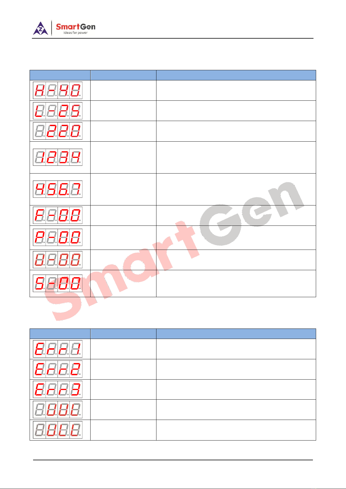
4-bit digital tube display is applied, which can display current coolant temperature, user defined
temperature, accumulated running time, accumulated energy consumption, current voltage
parameters etc.
Water flow sensor is fitted, which can quickly detect shortage of water, pipe gas gathering, pipe clog,
in order to prevent heater from dry burning, gas gathering etc. unhealthy phenomenon.
Circulation pump and heater are controlled separately; water pump is firstly started before heating,
and then heater starts after delay for 5s; when it reaches pre-set temperature point, heater power is
disconnected immediately; then water pump power is cut off after delay for 60s; this is to prevent
heat gathering so that it can prolong pump life.
Manual test function is fitted, which can check whether heating body and water pump is able to
operate normally through panel button.
Fine cast aluminum material is used for heater shell.
Stainless steel inner heating pipes.
Water drain valve is fitted at the bottom of the heating body, which can be used on demand.
This product can work normally at -40℃temperature.

HWP40N FORCEDCIRCULATIONHEATERUSERMANUAL
HWP40N Forced Circulation Heater Version 1.22020-12-11 Page 5 of 12
3. SPECIFICATION
Table 2 –Parameter Specification
Type
HWP40
Rated Power
4000W
Rated Voltage
AC 240V
Rated Current
16.7A
Phase
Single phase
Engine Displacement (L)
(15-30)L
Thermostat Range
Off: (5~70)ºC On: (0~65)ºC
Default Thermostat Range
Off: (40±2)ºC On: (25±2)ºC
Overheating Thermostat Range
Off: (95±3)ºC On: Manual
Insulating Resistance
≥50MΩ
Electrical Strength
AC 1.5kV 1min
Inlet/Outlet Size
G 3/4 Internal thread (Selectable Ф19.5mm Pagoda header or G 3/4
External thread)
Max. Water Pressure
0.5MPa
Pump Flow Velocity
40L/min (1.5m of lift)
Protection Level
IP44
Vibration Resistance
(5~8)Hz Amplitude±7.5mm Triaxial
(8~500)Hz a=2g Triaxial
Shock Resistance
Half-sine Wave; apeak=50g; Triaxial
Working Conditions
-40 ºC~+70 ºC
Storage Conditions
-40 ºC~+80 ºC
Case Dimensions
414 mm×261 mm×190 mm
Weight (include accessories)
5.3kg

HWP40N FORCEDCIRCULATIONHEATERUSERMANUAL
HWP40N Forced Circulation Heater Version 1.22020-12-11 Page 6 of 12
4. HEATER INSTALLATION
Please install the heater vertically according to the diagram before use. Pay attention to the direction of
heater inlet and outlet, and ensure that the heater position is below the lowest water level of the engine
and that all the air is exhausted out of the heater. Perfuse the heater with coolant.
Fig. 1 - Installation Plane Schematic
Fig. 2 –Installation Side Schematic

HWP40N FORCEDCIRCULATIONHEATERUSERMANUAL
HWP40N Forced Circulation Heater Version 1.22020-12-11 Page 7 of 12
5. OPERATING INSTRUCTIONS
5.1 BUTTON DESCRIPTION
Table 3 –Panel Display and Buttons
Button
Definition
Description
Heating
Press and if coolant temperature is below the set cut-off temperature,
heater will transfer to auto status; if coolant temperature is above the
set cut-off temperature, heater works for 15s and enters auto status
after commissioning.
Stop
Press and heater will stop.
Set
Press and enter parameter setting menu.
Up
Display the last digital cube content and do value adjustment.
Down
Display the next digital cube content and do value adjustment.
5.2 INDICATOR DESCRIPTION
Table 4 - Indicator Description
Sign
Definition
Description
Alarm
Alarm indicator
When lamp is illuminated, heater fault occurs and please decide fault
type according to the fault code of digital cube.
Auto/Heat
Auto/Heating
Heater is in auto state when it is flashing; it is in heating state when the
lamp is always illuminated.
Stop
Stop indicator
Heater is in stop state when lamp is illuminated.
ºC
Temp. indicator
They are used to indicate the type of value displayed on main
interface; after entering the password on display interface, press the up
button or down button, the running time indicator or power
consumption indicator is illuminated; when on the parameter value
interface, the calibration serial number interface,the software version
interface and the enter password interface, the four indicators flash
05.s once.
V
Volt. Indicator
10xHour
Running time
indicator
10xkWh
Power
consumption
indicator

HWP40N FORCEDCIRCULATIONHEATERUSERMANUAL
HWP40N Forced Circulation Heater Version 1.22020-12-11 Page 8 of 12
5.3 DISPALY ILLUSTRATION
Table 5 - Display Illustration
Sign
Definition
Description
Cut-off Temperature
The set value of target temperature
Reset Temperature
The set value of reset temperature
Current Voltage Value
It is current power voltage when V indicator is light on.
Accumulated Running
Time
It is total running time when 10×Hour indicator is light
on; unit is hour, detailed hours are the displayed number
x10; e.g. displayed number is 1234, and the actual hours
are 12340.
Accumulated Energy
Consumption
It is total energy consumption when 10×kWh indicator is
light on; unit is kWh; detailed kWh is the displayed
number x10; e.g. displayed number is 456.7, and the
actual kWh is 4567.
Water Flow Sensor
Enable
00: Disable; 01: Enable.
Dry Burning
Temperature Sensor
Enable
00: Disable 01: Enable.
Voltage Protection
Enable
00: Disable 01: Enable.
Start Mode
00: Power on manual start mode
01: Power on auto start mode
02: Keep the work mode before power off.
5.4 FAULT CODE
Table 6 - Fault Code
Sign
Definition
Description
Fault Code 1
Dry burning/water shortage protection.
Fault Code 2
Water temperature sensor open circuit.
Fault Code 3
Dry burning temperature sensor open circuit.
Over Voltage
Enters standby status when input voltage is over 264V.
Under Voltage
Enters standby status when input voltage is over 200V.

HWP40N FORCEDCIRCULATIONHEATERUSERMANUAL
HWP40N Forced Circulation Heater Version 1.22020-12-11 Page 9 of 12
5.5 OPERATION PANEL
Fig. 3 –Operation Panel Drawing
5.6 OPERATION DESCRIPTION
5.6.1 Parameter Check
Press and to switchover digital cube display and do value adjustment.
5.6.2 Commissioning
If water temperature is above pre-set reset temperature, press and heater will enter
commissioning status, and it will transfer to auto status after heating for 10s.
5.6.3 Parameter Setting
Press and enter parameter setting menu, and it will display (H means the
set temperature is cut-off temperature value, 40℃is only an example). Press again to enter
the setting, and adjust values by and . Press again to move or confirm. Press
and it will go back to the main menu. It will also return back to first page if there is no
operation within 1 minute.

HWP40N FORCEDCIRCULATIONHEATERUSERMANUAL
HWP40N Forced Circulation Heater Version 1.22020-12-11 Page 10 of 12
6. USE AND MAINTENANCE
1) After it is connected with power, heater is at stop state. Press Auto/Heat and make heater enter
working status.
2) When it needs to be checked/fixed or change pipe or some part, press Stop and make heater enter
stop status.
3) Before start please confirm whether heater is fully filled with coolant and make gas in the pipe
exhausted by vent valve.
4) It is strongly suggested to use antifreezing solution with corresponding mark number.
5) If ordinary water is used, users must drain the water after stop when environment temperature is
below 0℃, in order to prevent the water in the heater getting frozen and resulting in heater fracture.
6) GND wire must be earth connected.
7) Drain valve: shall be opened or closed by hexagonal flower tool.
Fig. 4 –Vent Valve Indicating Diagram
Fig. 5 Wire Connection
Fig. 6 Vent Valve Size

HWP40N FORCEDCIRCULATIONHEATERUSERMANUAL
HWP40N Forced Circulation Heater Version 1.22020-12-11 Page 11 of 12
7. CASE AND DIMENSIONS
Fig. 7 –Overall Dimensions (Unit: mm)
NOTE: all the inlets/outlet connectors are internal thread G 3/4.
8. Pack List
Table 7 - Pack List
No.
Name/Model
Number for one unit
1
Product
1
2
Stand
2
3
Flat Gasket GB/T 95 8
8
4
Spring Washer GB/T 93 8
8
5
Hexagon Nut GB/T 41 M8
8
6
Hexagon Slot GB/T 5783 M8×40
8
7
User Manual
1

HWP40N FORCEDCIRCULATIONHEATERUSERMANUAL
HWP40N Forced Circulation Heater Version 1.22020-12-11 Page 12 of 12
Table 8 - Water Gate Accessories
No.
Name/Model
Number for one unit
1
Ф19.5mm Pagoda Joint
2
2
G 3/4 Stainless steel pair screw
2
3
ED Sealing gasket
2
Fig. 8 Pagoda Header Size (Unit: mm)
Fig. 9 Pair Screw Size (Unit: mm)
_________________________________
Table of contents
Other Smartgen Heater manuals
Popular Heater manuals by other brands

Dimplex
Dimplex BPH100M instruction manual

Frico
Frico PAEC3200C-NA Series Original instructions

Saunatec
Saunatec Wood burning sauna heaters Installation and user manual

Living & Co
Living & Co LOH200011W instruction manual

Kroll
Kroll M25 Instruction handbook

Safe-t-Cover
Safe-t-Cover 400LU880 Assembly instructions