Smarti Pi Touch Pro W User manual

Assembly instructions
Drawings and CAD files are available at smarticase.com
W
Raspberry Pi Bullseye issues
Pi OS Bullseye was released in November 2021. There are a number of issues rotating the camera
image in Bullseye. Raspistill and raspivid rotation are not supported. If you are having issues rotating
the camera image , please try Pi OS Buster. It is available in the Raspberry Pi imager under Raspberry
Pi OS (other). Buster will be supported until 2024.
Compatiblity
These are instructions to assemble the SmartiPi Touch Pro W.
The SmartiPi Touch Pro W is compatible with the
- Waveshare Capacitive Touch 1024×600 DSI display ( Model/Sku 20429 )
- Raspberry 4B/3B+/3A+
https://www.waveshare.com/product/raspberry-pi/displays/7inch-dsi-lcd-c.htm
https://www.waveshare.com/wiki/7inch_DSI_LCD_(C)
Product page for the Waveshare display
Drivers and setup for the display are at the link below. These are required for it to function.

Power supply
Always use a UL or CE marked wall power supply with the included splitter cable. Use a wall power
supply that can deliver enough current for your application. For best results, use a 5.1 volt power
supply to avoid low voltage warnings on the display. The official Raspberry Pi power supply is recom-
mended.
The splitter cable is only for use with the SmartiPi Touch Pro W.
Step 1
Insert the female end into the back cover as shown below. The cable can be assembled in either of
two positions. Option 1 extends further out for easier access. Option 2 is the more compact option.
option 1 option 2
5V 3A USB-C Power
supply recommended
USB-C input
USB-C for use with Pi 4
Micro USB for use
with Pi 3
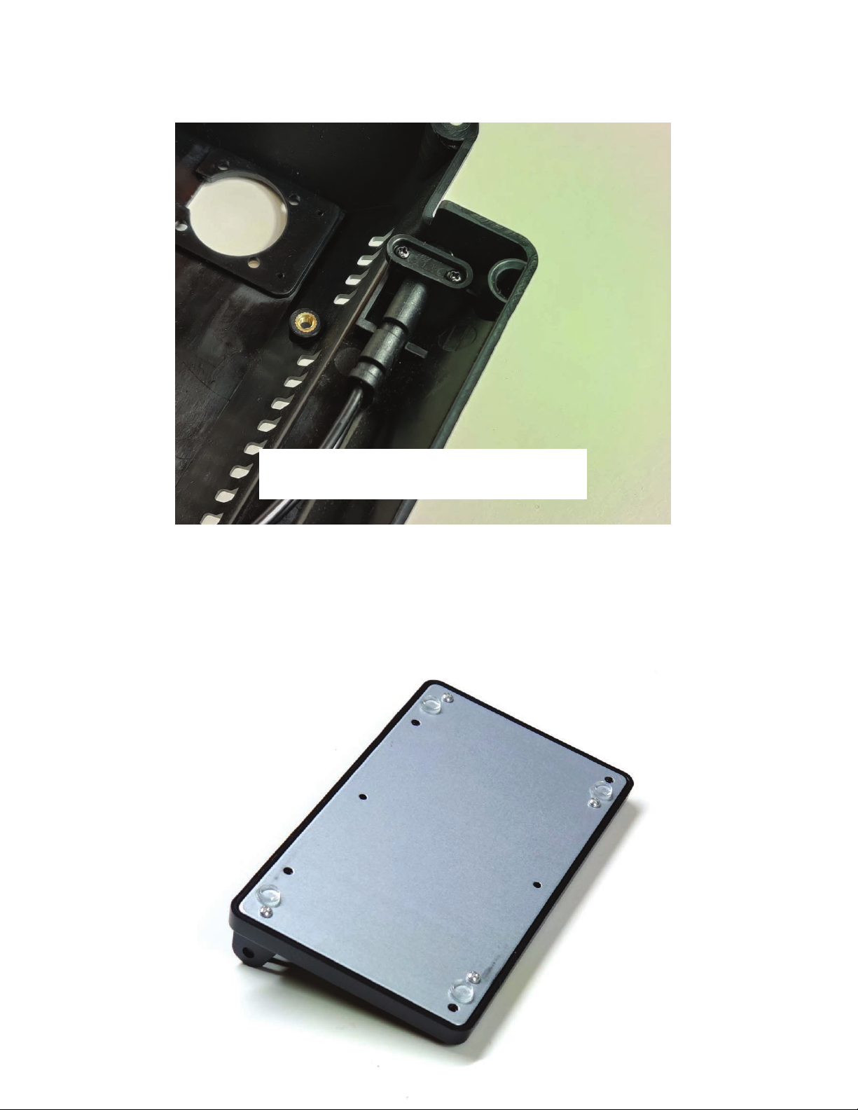
Step 2
Use the two small black screws to secure the small plastic retaining part to the back cover. This
will hold the power cable in the case.
Step 3
Assemble the metal base on the bottom of the plastic base. The metal base can only properly assemble
onto the base one way. Please make sure all of the holes are aligned. Use the four silver screws to
attach the metal base to the plastic base. Assemble the screws as shown in the photo. Then assemble
the adhesive rubber feet in the locations show below.
Do not overtighten the screws!
Step 4
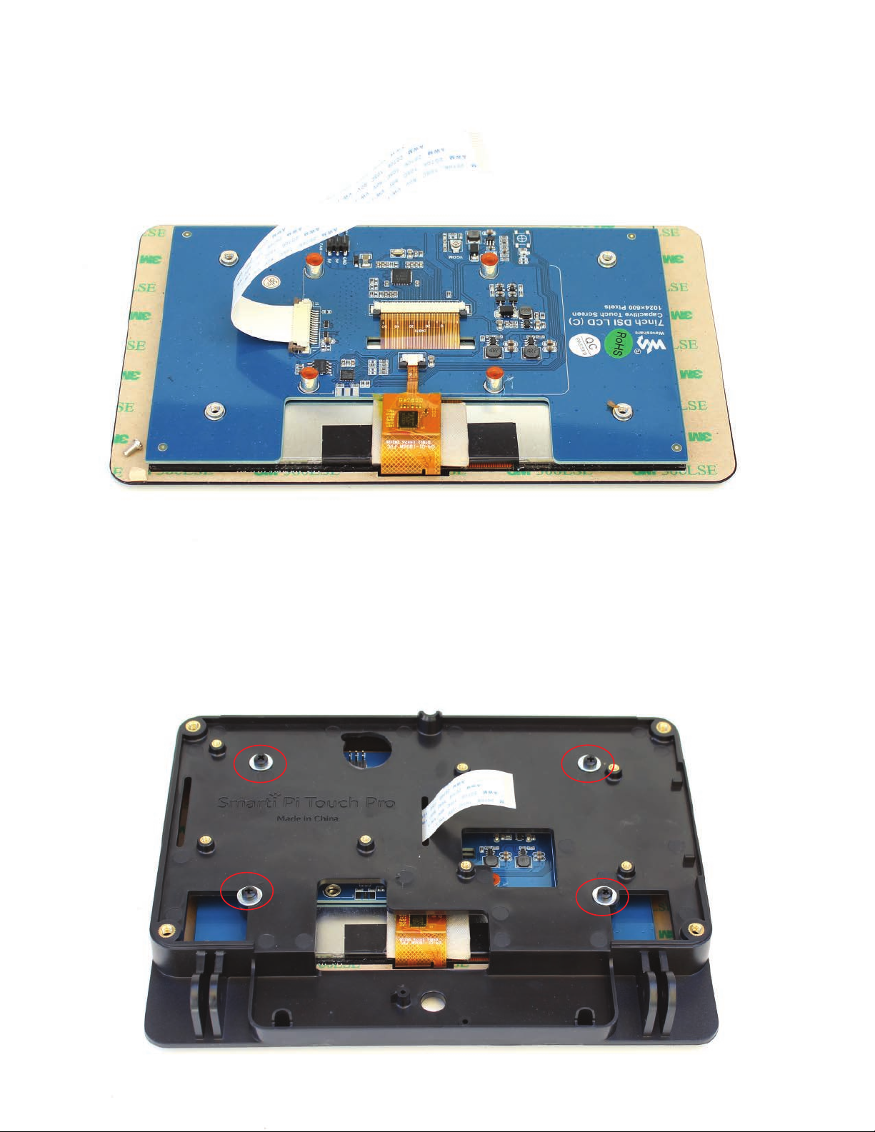
Step 5
Assemble one of the white ribbon cables with the contacts facing up to the display connection on the
display board.
Attach the display to the case with the four plastic screws and metal washers that came in the bag by
themselves. Route the display cable through the slot as shown.

Step 6
Attach the Raspberry Pi to the housing with the gold standoffs that came with the display.
Use the short bundle of four jumper wires to attach the Raspberry Pi GPIO to the display as shown by the
diagram below. Attach the white display cable to the Raspberry Pi DSI connector as shown below.
Connect the fan to the display using the remaining pins on the display using the supplied jumper
extension wires. Please make sure to connect the red on the fan to the 5V and the black on the fan
to the GND. The color of the supplied jumper extensions will vary.
https://www.waveshare.com/wiki/7inch_DSI_LCD_(C)
Drivers and setup for the display are at the link below. These are required for it to function.

Step 7
If you want to use HAT boards you have two options.
Option 1 - Stack the HAT directly on top of the Pi and purchase longer female to female jumper
wires ( not included ) to attach the display to the GPIO pins on the HAT. You will need to make sure
the HAT is not using the same GPIO pins as the display. Most HATS allow you pass through the
pins so they are accessible on the top.
Option 2 - Attach the HAT to the other mounting area with three threaded standoff risers (not included)
to avoid the GPIO jumper cables on the display. You would then need to use jumper cables to
attach the HAT to the Pi GPIO pins it requires to function.

Step 8
If you choose to use the camera hole, the Official Raspberry Pi camera can be assemble into the
the camera hole with two of the small black screws. If you are not using the camera, proceed to Step 9.
Do not overtighten the screws!
To rotate the camera image 180 degrees
In a command line enter
sudo nano /etc/rc.local
Then go down and enter the following code above exit 0
v4l2-ctl --set-ctrl=rotate=180
Then enter CTRL+O to write out the file , then
press Enter to confirm and then CTRL-X to exit.
Once rebooted that should have the camera rotated
the correct way for most applications.
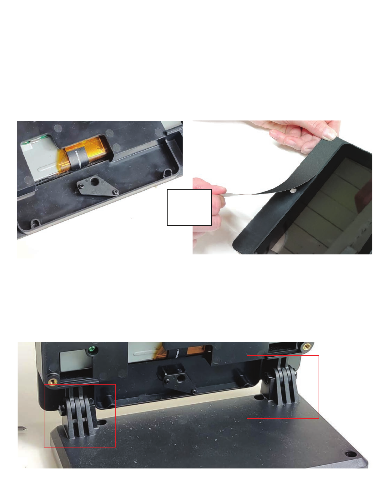
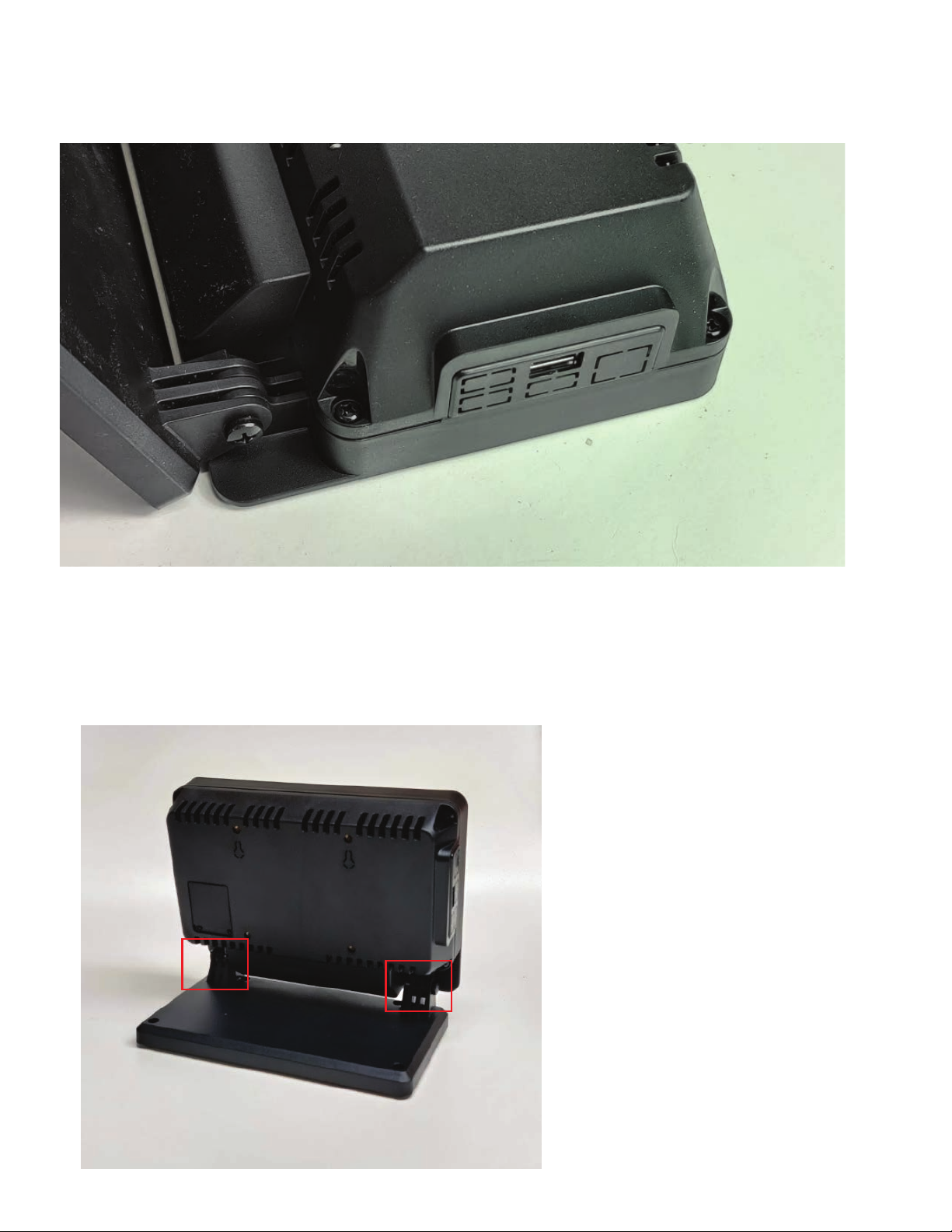
Step 10
Assemble the display housing to the stand with the large black screws and nuts.
DO NOT OVERTIGHTEN. Loosely attach the screws at this point.
If you chose to not use the camera, you can temporarily plug the hole with the small plastic cover
part with two of the small black screws.
Alternatively, you can permanently cover the camera hole with the adhesive front panel. Do not have the
plastic camera cover part installed when you apply the adhesive panel. The adhesive panel is not
removable.
Step 9
Or
Custom artwork and logos can be added to this adhesive
panel for bulk quantity purchases. Contact us for more
info.

Step 11
If you choose to not use the fan, the small door can be assembled into the hole in the back cover and
attach with two of the small black screws.
Step 12
If you choose to use the fan , attach the small rubber vibration mounts to the holes in the back cover
as shown below. Push the small end of the mount through the back cover from the outside. Then pull
it through the cover as shown.

Then pull the rubbers mounts through the fan holes and pull the thin end of the mount until the
fan is mounted on the rubber mount as shown below. The fan should only be mounted in the way as
shown below.
Step 13
Step 14
Attach the supplied jumper cable extenders to the red and black on the fan. The color of the jumpers
may vary. Make sure the red on the fan is connected to the 5v on the display and the black is connected
to the GND on the display.
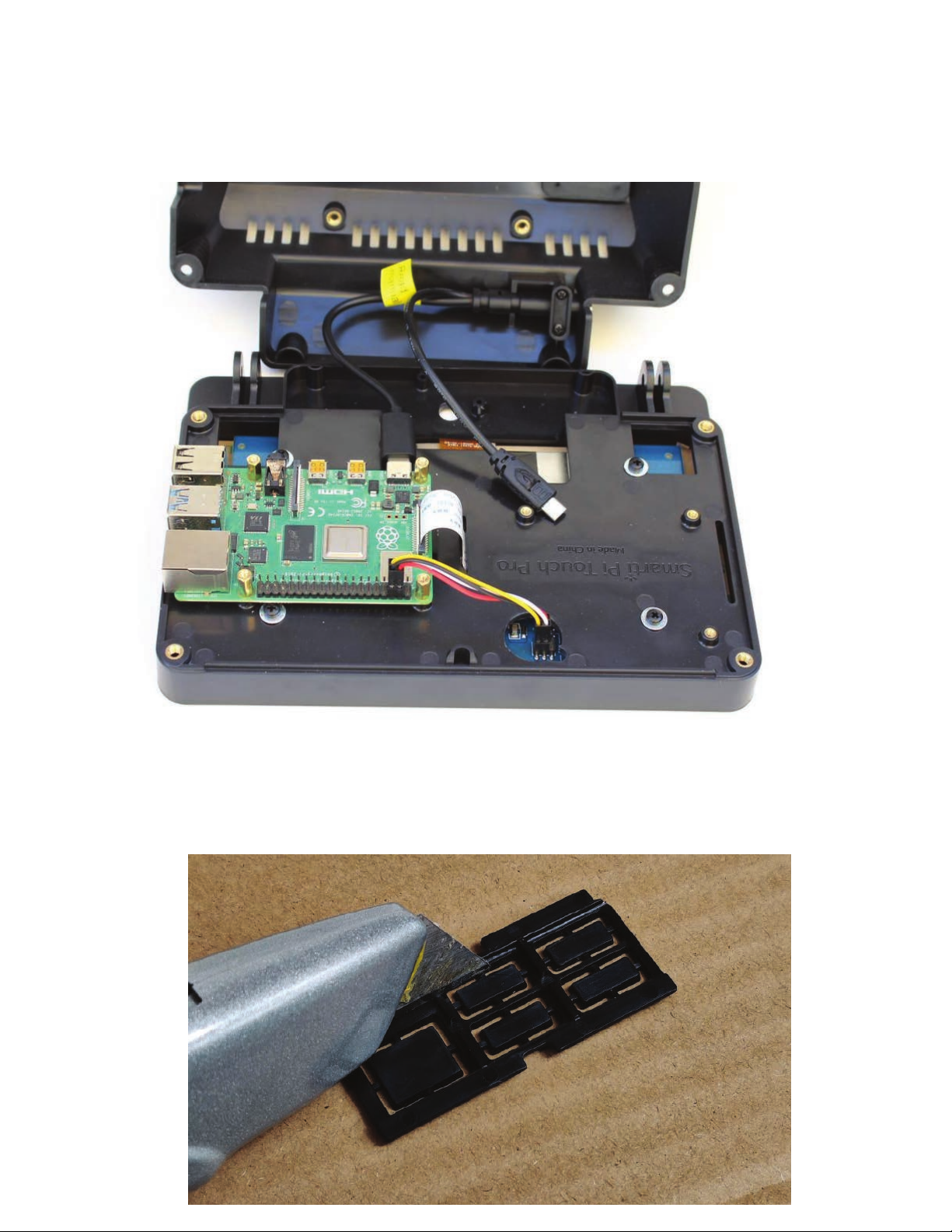
Step 16
If using the port blocking part, from the back side cut out the desired ports with a utility knife.
Two parts are included. One for Pi 2/3 and one for Pi 4.
Attach the power cables to the Pi. If using Pi 4, use the USB-C , if using the Pi 3 and below
use the micro USB end.
Step 15
Assemble the back cover to the display housing with the four black screws.
The port blocking part should have tabs that fit inside the housing and cover.
Step 17
Step 18
Adjust the angle of the display to suit you needs. Then tighten the pivot screws.
DO NOT OVERTIGHTEN. Tighten the screws just enough to hold the display in place.
You will have 4 green screws left when you are done. This is not a mistake.
These are prepackaged with the hardware and are for the version of the product that is compatible with
the Raspberry Pi official display. Please discard them.
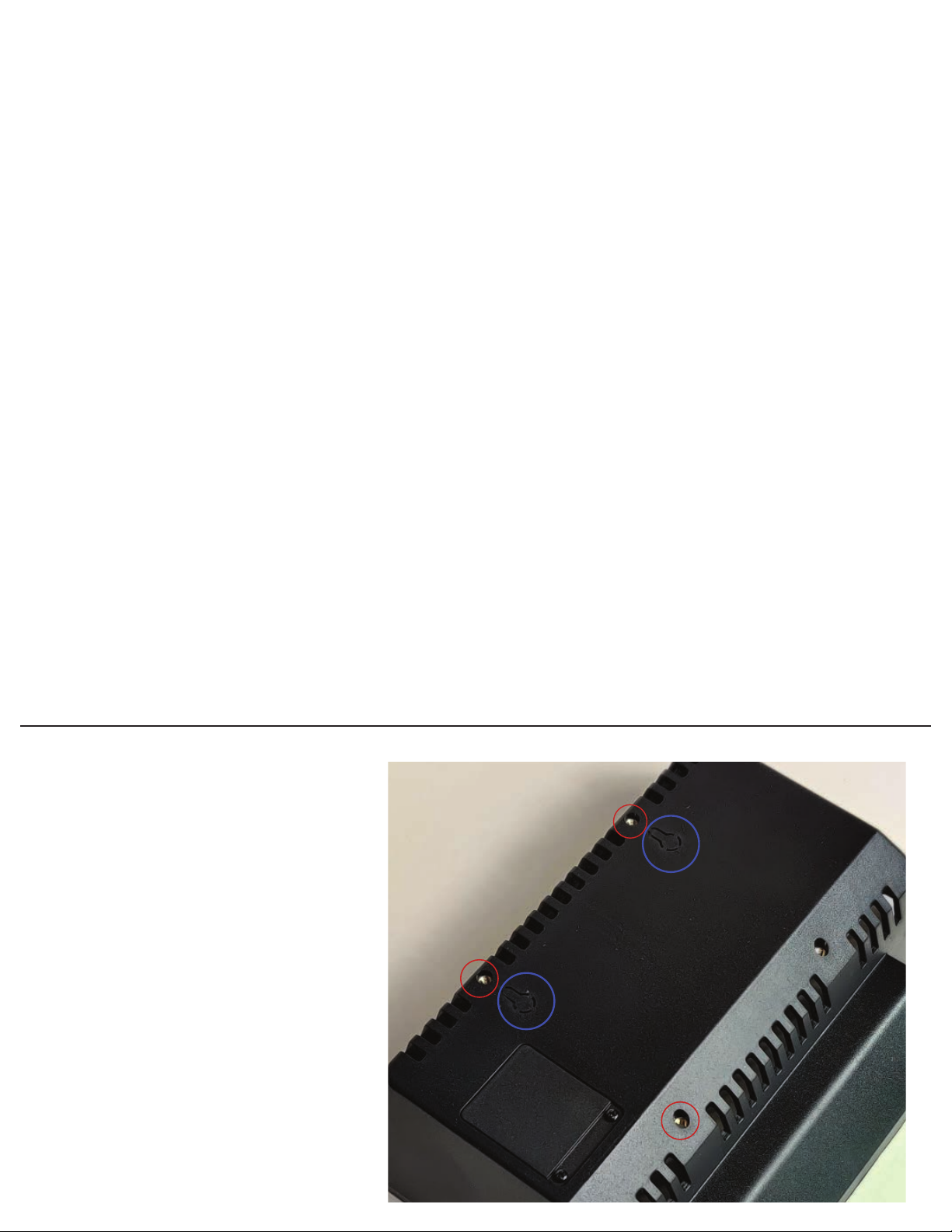
75mm VESA mounts (circled in red) can
be used to mount the display housing
instead of using the stand. The threaded
holes are size m4
Two eyelets can be cut out with a utility
knife (circled in blue ) to mount to a
surface. The mounting points are 75mm
apart.
VESA mounts
Green screws left over?
Table of contents


