manuals.online logo
Brands
  1. Home
  2. •
  3. Brands
  4. •
  5. SMB
  6. •
  7. Play Set & Playground Equipment
  8. •
  9. SMB Carrantuohill Manual

SMB Carrantuohill Manual

Technical Information
Carrantuohill
Page 1
Installation Instructions EN 1176-1
Maintenance Instructions EN 1176-1
10.10.14
General
The operations described are to be carried out by a specialist.
The climbing frame is fixed on a galvanised square tubular frame. Concreting is not necessary. It is easy to
change the location without the bases
having to be removed or remaining in
the soil.
Dimensions
Effective space 2.99 x 2.99 m
Drop 1.55m
Minimum space 6.09 x 6.09m
Height 2.99m
Age group
4 years upwards
Number of users
About 15 children
Maximum free drop height
1.57 m
Figure 1 Type Carrantuohill
Ground quality
With regard to the type of ground in the play area, please refer to EN 1176-1. According to this, sand, wood
chips, gravel and HIC tested synthetic protective coatings are allowed. We recommend a min. 400 mm thick
layer of gravel (grain size 2 –8 mm) or sand (grain size 0.2 - 2 mm). If you use a synthetic protective surface
it must be sure that all relevant parts for the maintenance (see maintenance instruction on page 4) are every
time accessibly. If necessary consult SMB.
Assembly tools
Tools supplied: Additional tools required:
1 size 32 socket spanner with extension 2 size 24 open-jawed spanners
1 size 10 Allen key 1 electric screwdriver for special bits
2 special bits for securing screws 1 double ladder, approx. 3 m long
1 size 27socket spanner normal assembly tools
Figure 3 Arrangement of the frame tubes and ball joints
Ball joints frame tubes
1x K1 1X R1 3x R5
4x K4 1X R2 1x R6
4x K7 1x R3 4x R7
1x R4 4x R8
Technical Information smb
Carrantuohill Seilspielgeräte GmbH Berlin
Page 2 Technikerstraße 6/8
15366 Hoppegarten
Germany
Phone: ++49 (0)3342 5 08 37 20
Fax: ++49 (0)3342 5 08 37 80
Assembling the anchoring frame
Screw down the galvanised square tubular frame with
the plug-in system as shown in figure 2.
This frame must be placed in the soil at a depth of
470 mm below the play level (figure 2), and must be
level and square.
This framework ensures that the frame tubes and the
hollow balls can be screwed in correctly.
1 Plug-in frame Part 1
2 Plug-in frame Part 2
3 Plug-in frame Part 3
4 Tube anchor
Figure 2 Anchoring frame
Assembling the frame
An approx. 3 m long double
ladder will be required for
assembly. The arrangement
of the frame tubes and ball
joints is shown in figure 3.
The reference number printed
on the joints (K4/K7) always
points to the top of the frame
(K1).
After completing the preas-
sembly of the frame, but
initially only partially tightening
the screw connections, check
the correct alignment of the
ROWOCON® - connections
regarding the adjustment of
the nets (see figure 4 and 5).
All the nuts can then be
tightened with the extended
socket spanner size 32.
Figure 5 Alignment and fastening
of the ROWOCON® sleeves
Figure 4 Arrangement of the nets (Illustration with inside
netting as additional element)
2x N1 1x N4 inside netting (if ordered)
1x N2 1x NH horizontal netting
4x N3
Figure 6 bring in of the rope ends
into the ROWOCON® sleeves
Technical Information smb
Carrantuohill Seilspielgeräte GmbH Berlin
Page 3 Technikerstraße 6/8
15366 Hoppegarten
Germany
Phone: ++49 (0)3342 5 08 37 20
Fax: ++49 (0)3342 5 08 37 80
Assembling the surface netting
The horizontal net (NH) should be fitted first. Insert the rope ends on the slide side into the ROWOCON®
sleeves as far as they will go
and fasten them with the
securing screws provided
(figure 5 and 6). If individual
rope ends should insert only
with difficulty, you can help
yourself with an injection of
silicon or oil in the
ROWOCON® sleeves. In no
case it is allowed to remove
the end sleeve of the rope!
Then fasten the opposite side,
using the hemp rope to provi-
sionally tighten the net, which
will make threading and
screwing down easier.
The two remaining sides of
the net can then be screwed
down.
The four lower triangular
nets (N3) can then be fitted
similarly, followed by the
three upper trapeze nets (N1
and N2).
Caution:
If you bring in the rope ends into the ROWOCON®-sleeves and the following screwing
with the safety screw it must be sure that the rope ends are into the sleeves as far as
they will go. The safety screw must not screw through the aluminium sleeve at the end
of the rope (fig. 6). Otherwise the rope will be damaged.
Figure 7 lock nut at K7
Technical Information smb
Carrantuohill Seilspielgeräte GmbH Berlin
Page 4 Technikerstraße 6/8
15366 Hoppegarten
Germany
Phone: ++49 (0)3342 5 08 37 20
Fax: ++49 (0)3342 5 08 37 80
Assembling the additional element inside netting (if ordered)
With the hollow balls still open, pull the marked straining screws
into the corresponding hollow balls (K4 and K7) via the
tensioning sleeves (size 27), thereby tightening the inside
netting. The lock nuts (size 24) on the straining screws can then
be tightened (figure 7).
Closure of the open hollow balls with the prepared ball covers
completes the assembly.
Locking the hollow balls
Lock the hollow balls with the prepared ball covers.
Maintenance instructions EN 1176-1
Visual routine inspection
Frequency will be based on local conditions (high/low use, vandalism, air pollution, effects of weather).
The surface netting should be examined for damage, especially broken strands.
The cover locks for the hollow balls should be checked.
Operational inspection (twice-yearly)
The additional element inside netting (if fitted) should be checked for tautness. Retensioning is carried
out at the tensioning point by removing the cover and increasing the tension on the tensioning sleeve
(size 27). The lock nut (size 24) (figure 7) should first be loosened. Normally retensioning at the upper
tensioning points will be sufficient (K4)
Main inspection (annual)
In addition to the checks in the visual and operational inspection:
Check the anchor frame for excessive corrosion (every two years). At the corners the anchor frame
should be exposed to the installation depth and checked for corrosion.
Check that the tube screw fittings have a firm, crack-free connection to the hollow balls. If a screw fitting
is loosened, it should be re-tightened inside the ball.
Check that the lock nuts (figure 7) fit firmly on the hollow balls.

Other SMB Play Set & Playground Equipment manuals

SMB Ben Nevis User manual

SMB

SMB Ben Nevis User manual

SMB TRAMPOLINE S Manual

SMB

SMB TRAMPOLINE S Manual

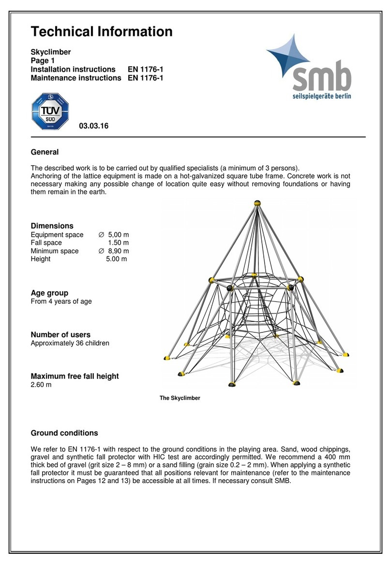
SMB Skyclimber Manual

SMB

SMB Skyclimber Manual

Popular Play Set & Playground Equipment manuals by other brands

Playcraft Transfer Station with Half Walls 1209-HW installation instructions

Playcraft

Playcraft Transfer Station with Half Walls 1209-HW installation instructions

Playcraft GLIDE-N-TWIST RV-1917 installation instructions

Playcraft

Playcraft GLIDE-N-TWIST RV-1917 installation instructions

Plum 27505AA69 manual

Plum

Plum 27505AA69 manual

INNOVAPLAS BILTMOR 5015 Manufacturer's Instructions

INNOVAPLAS

INNOVAPLAS BILTMOR 5015 Manufacturer's Instructions

WOODPLAY PG123MRW quick start guide

WOODPLAY

WOODPLAY PG123MRW quick start guide

Mercia Garden Products 02PLM0404-V1 General instructions

Mercia Garden Products

Mercia Garden Products 02PLM0404-V1 General instructions

BOERPLAY PSTE105.036 manual

BOERPLAY

BOERPLAY PSTE105.036 manual

Rompa 21557 quick start guide

Rompa

Rompa 21557 quick start guide

forest-style Marina 002664 manual

forest-style

forest-style Marina 002664 manual

Martin Mena Flor bailarina Assembling manual

Martin Mena

Martin Mena Flor bailarina Assembling manual

Funky Combo LION installation instructions

Funky Combo

Funky Combo LION installation instructions

Gymax GYM04202 user manual

Gymax

Gymax GYM04202 user manual

KBT reX Instructions for use

KBT

KBT reX Instructions for use

BOERPLAY BBPE113.3BP installation instructions

BOERPLAY

BOERPLAY BBPE113.3BP installation instructions

Sove 16-402-100 Assembly instructions

Sove

Sove 16-402-100 Assembly instructions

Trigano CONDOR Assembling instructions

Trigano

Trigano CONDOR Assembling instructions

Fungoo Boomer 2 installation instructions

Fungoo

Fungoo Boomer 2 installation instructions

BOERPLAY BBPE412.6BR installation instructions

BOERPLAY

BOERPLAY BBPE412.6BR installation instructions

manuals.online logo
manuals.online logoBrands
  • About & Mission
  • Contact us
  • Privacy Policy
  • Terms and Conditions

Copyright 2025 Manuals.Online. All Rights Reserved.