SMI Group NetPrinter NP812 User manual
COB (Calibration On Board)
Installation instructions
NetPrinter
17886-022-1
NPDS
NP812

1

2
NETPRINTER
COB
THE COB KIT 18955.040.1 IS MADE UP OF:
Description Part Number Quantity
ArtixScan 1100 002113210 1
Kit software* 18074.105.9 1
*The kit software 18074.105.9 is made up of:
•N°1 CDROM Netprinter including:
-CORE SW W-15 Installation
-COB V-50 Installation
-SMI1200 3.xx Installation
-PRINT MATE Installation
-TEST IMAGES Copy to D:\
•Software Installation Instructions
•COB Installation Instructions
•Print Mate Program User’s guide
•NetPrinter Operating Manual
•N°1 Set EPROMs
TOOLS REQUIRED:
Standard service tools

3
KIT INSTALLATION
1. Switch OFF the PC and
disconnect the plug from the
mains power supply.
2. Release the PC front panel by
unlocking at the bottom with a
finger. Remove the panel
3. Remove screw A
A
1
2

4
4. Pull off the left lateral panel
5. Remove the metal plate on the PC
back panel to insert theSCSI
board
6. Insert the SCSIboard in the PCI
slot
PCI slot
PCI slot
5
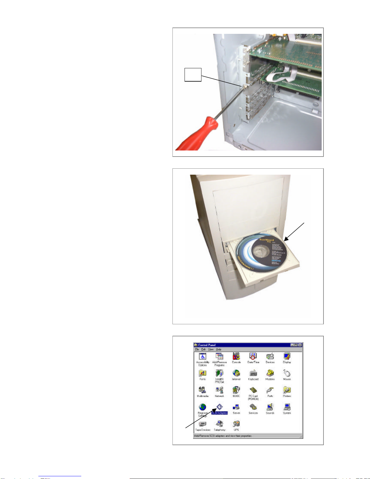
7. Secure the SCSI board with a
appropriate screw C.
8. Reinsert the lateral panel and
remount the PC front panel
9. Insert the scanner driver CD in the
PC
10. Suht down the SMI 1200
software
11. From Windows select
Start/Settings/Control
Panel/SCSI Adapters
C

6
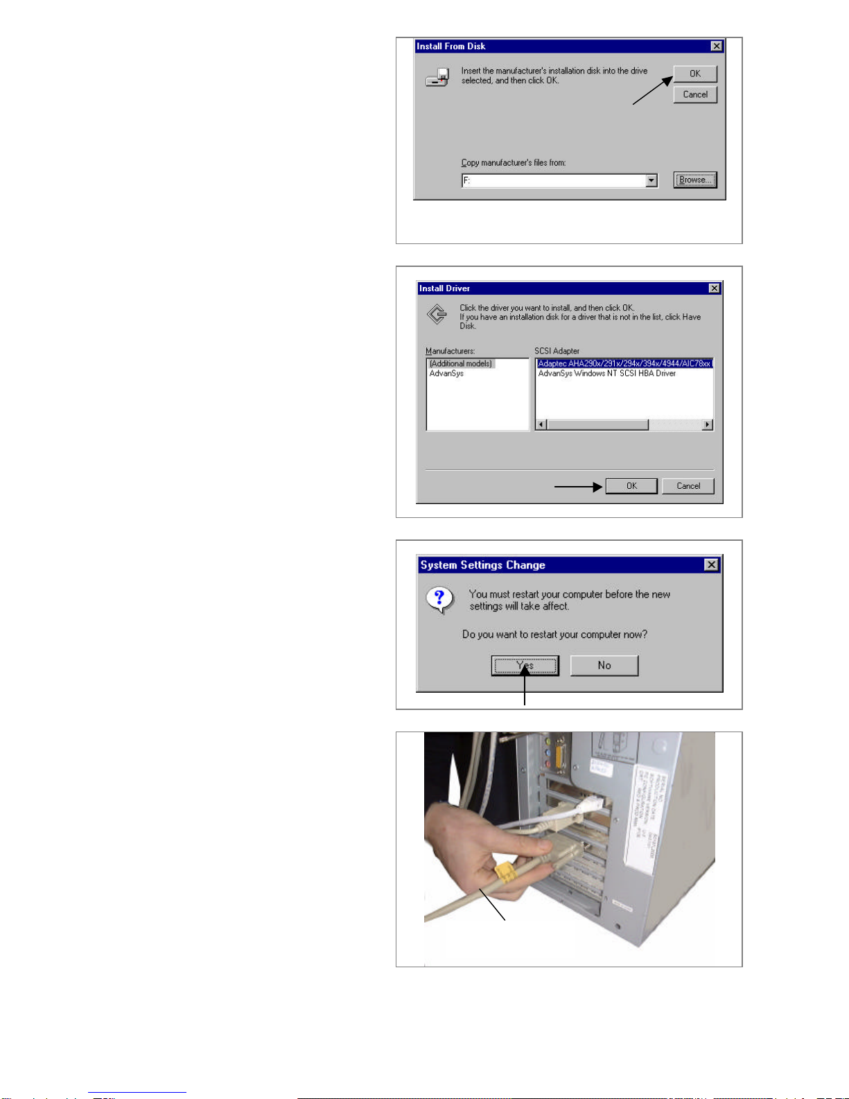
12. Select Drivers and Add
13. Click on Have Disk
14. With Browse select the CD
ROM (F:\)
15. In Locate File select
Adaptec_NT.inf., click on
OPEN and confirm with OK
7
16. Click OK
17. Select the first option (Adaptec
HAH290x/……) and confirm
with OK.The scanner drive
program is installed
18. Click on Yes to restart the PC
19. If no SCSI error messages
appear, switch OFF the PC.
20. Connect the SCSI cable to the
scanner board connection
SCSI cable

8
21. Rest the scanner on a side and
turn the blocking screw Eat the
bottom, to unlock the optics
22. Position the ID selector on 6
and the SCSI TERMINATOR
at ON (towards the top)
23. Insert the SCSI cable connector
Din the scanner connection
24. Connect the mains cord to the
scanner and to the mains
power supply
ID selector
SCSI TERMINATOR selector
E
D

9
25. Press the ON/OFF button to
switch ON the scanner
26. The inside of the cover
Fmust be white.
If black, then cover it with a
white paper sheet having the
same dimensions and use
transparent sticky tape to
secure this paper to the inside
of the scanner
27. Switch ON the PC
28. Close the SMI 1200 software
F
10
29. Locate the ScanWizard Pro
Software CD-ROM
30. Stop the NetPrinter Software.
31. Load the ScanWizard Pro CD-
ROM into the computer
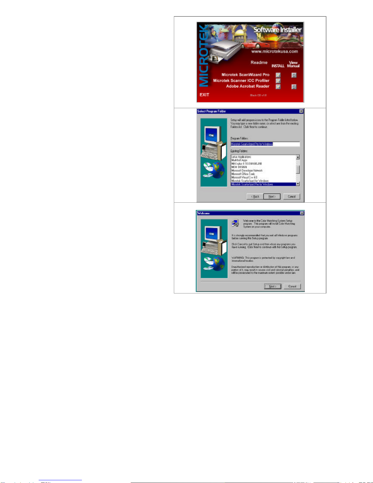
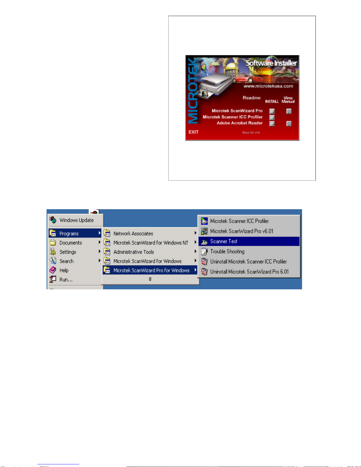
32. The installation wizard will
display.
33. Select Microtek ScanWizard
Pro Install and press the
button
34. On the Welcomescreen, press
Next.
35. On the Select Program Folder
screen, select Next.
36. As ScanWizard Pro is
installed, a progress bar is
displayed.
37. The Welcomescreen displays
again indicating that the Color
Matching System Setup will
now take place.
38. Press Cancelto exit this setup
11
39. The initial setup screen will
display.
40. Press the Install button next to
the Microtek Scanner ICC
Profiler.
41. On the Welcomescreen, press
Next.
42. On the Select Program Folder
screen, select Next.
43. As ICC Profiler is installed, a
progress bar is displayed.
44. The final window that displays
recommends that the computer
be rebooted before using
ScanWizard Pro. Press
Finish, and the computer will
reboot automatically.
45. If the Computer does not
reboot, reboot manually
46. Stop the NetPrinter Software
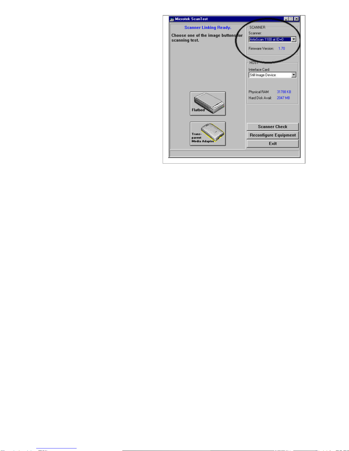
47. At this point, run the Scanner Test to verify the connection to the scanner.
12
48. Verify that the scanner comes
up in the scanner box.
Note: You might have to turn
the scanner power on, then
power down the computer, then
reboot to get a confirmed
connection to the scanner.
Refer to the Microtek scanner
documentation to help you
through any problems you
encounter.
49. Click EXIT

13
50. Open ScanWizard Pro.
51. Open the Scanner menu
52. Verify the correct scanner is
selected: ArtixScan 1100.ID=x
53. Then Select Scanner Control.
54. Press the Lamp tab
55. Change Idle time to 60 Minutes
56. Change warm up time to 1
Minutes
57. Press the Scanner Calibration
tab.
58. Preview Automatic
59. Final Scan Automatic
60. Press the OK button

14
61. Open the Preferences menu
62. Verify the DCR Color Control
is Selected.
63. If there is a check mark on the
left of the DCR Color
Correction, it is selected.
64. Select Overview Setup.
65. Change Size to Maximum
size.
66. Press the OK button.
67. Open the Preferences menu
and select More
68. Confirmation Message:
Checked
69. Verify the Color Space Mode
is:
Native.
70. Change the Scan Mode
to:Best Quality
71. Press the OK button.
72. Close Scan Wizard.

15
How to solve certain problems, which may arise when
installing the scanner
1) If after the scanner is connected to the PC and the machine restarted it refuses to
restart (blocks on the Windows initial screen) it is necessary to force a restart with
the PC switch.
2) If after carrying out step 1 the PC still refuses to restart, switch the PC OFF,
disconnect the scanner, (switch the scanner OFF before disconnecting from the
SCSI assembly) disconnect the SCSI cable from the PC and restart the PC.
3) If after carrying out step 2 the PC starts without problems, then there could be a
scanner hardware malfunction or a defective SCSI cable. In this case proceed as
follows:
•Replace the SCSI cable. If after replacing the cable the PC restarts correctly
then the problem is the cable.
•If after replacing the cable, the PC blocks again, then the problem is caused by
the scanner hardware.
The scanner is not recognized
1) If after the installation is completed and the PC restarted (with the scanner
connected) and Scanner Test (to be found in the windows programs) executed, no
scanner is detected, then restart the PC.
2) If after carrying out step 1 the Scanner Test still does not recognized the scanner
then make sure the SCSI controller has been installed correctly (check peripheral
management to see if problems are signaled in the SCSI controller properties).
3) If after carrying out step 2 problems are found with the SCSI controller then restore
the driver or replace the controller.
4) If after carrying out step 2 no problems are found, then the problem is attributable to
the scanner.
The scanner presents problem in scans
1) If there are any problems with scanning (lines, various errors, the scanner or PC
blocks, etc) then check if the problem occurs with one or the other programs
(Scanwizard or SilverFast). If the problem persists when using either software, then
the software must be updated (if the SW is an old version) from various websites.
http://www.microtekusa.com/support.html
http://www.silverfast.com/english/

16
2) If after carrying out step 1 the problem persists, then the scanner is faulty.
3) If after executing a scan the scanner makes pronounced metallic sounds or gear
“scraping” sounds, then the scanner is the problem.
4) If after starting a scan the scanner lamp does not switch ON then the scanner is the
problem.
5) If the scanner blocks after a scan is started consequently blocking the system, then
the scanner is the problem.
6) If the scanner signals an error or in any case does not scan even after various
attempts (after restarting the machine and the scanner a few times), then the
scanner is the problem.
7) If on the acquisition one or more lines appear along the whole image, then the
scanner is the problem (probably a CCD or lamp problem).
8) If the acquired image appears completely out of focus, then the scanner is the
problem.
Scanner test (with scanner disconnected from the PC)
1) The test, which the scanner carries out automatically when switched ON is very
important because it serves to determine if the scanner has hardware problems.
The test, which follows, is an optical group positioning and lamp check test (it lasts
about 40/60s).
If the scanner failure is mechanical, then soon after switch ON (testing phase), the
LEDs will blink for 40/60s and then remain lit.
If all three LEDs remain lit then the optical groups move correctly.
If the LEDs continue blinking then the scanner has optical groups damaged.
2) With the scanner OFF set the ID to n° 7 then switch ON the scanner.
In this configuration the scanner carries out a loop-test. The scanner optical groups
move as if they were scanning. The scanner carries out alternately a reflection and
transmission scan in a continuous cycle. To interrupt the cycle, switch OFF the
scanner and reposition the ID on 6.
3) Repeat the procedure of step 2 with the ID on 8.
4) If the scanner does not carry out these operations then it is faulty.
This manual suits for next models
2
Table of contents
Popular Printer Accessories manuals by other brands


Ricoh
Ricoh PB1170 Field service manual

Epson
Epson T033120 Product information sheet

Martin Yale
Martin Yale 959 Installation, operation & maintenance instructions

Canon
Canon Color UFRII Printer Kit-L1 Service manual

TonerRefillKits
TonerRefillKits ReChargX RX139 instructions

Xerox
Xerox 3600B - Phaser B/W Laser Printer Install instructions


