Smitec POSYC 3401 Service manual

Industrial computers POSYC 3401/3402 Installation, use and maintenance manual - EN
Ver. 1.03 1
Smitec S.p.A., viale Vittorio Veneto 4, 24016 San Pellegrino Terme (BG), Italy, www.smitec.it
Installation, use and maintenance manual
INDUSTRIAL COMPUTERS
POSYC 3401/3402
BEFORE STARTING UP THE INDUSTRIAL COMPUTERS POSYC 3401/3402, CARE-
FULLY READ THIS MANUAL AND FOLLOW ALL INSTRUCTIONS, IN ORDER TO EN-
SURE MAXIMUM SAFETY
The technical data and the drawings in this manual might have been modified later; always
refer to the latest version.

Industrial computers POSYC 3401/3402 Installation, use and maintenance manual - EN
Ver. 1.03 2
Summary
1 Preface ....................................................................................................................................................... 3
2 General warnings ...................................................................................................................................... 4
3 Safety instructions .................................................................................................................................... 6
3.1 General information ............................................................................................................................ 6
3.2 Precautions during handling and assembly ........................................................................................ 6
4 Product description .................................................................................................................................. 7
5 Technical data ........................................................................................................................................... 8
5.1 Electrical characteristics ..................................................................................................................... 8
5.2 Electrical characteristics ..................................................................................................................... 8
5.3 Mechanical characteristics .................................................................................................................. 9
5.3.1 Mechanical dimensions ............................................................................................................... 9
5.3.1.1 Front view ............................................................................................................................ 9
5.3.1.2 Side view ........................................................................................................................... 10
5.3.1.3 Rear view (recommended panel cut)................................................................................. 11
5.4 Hardware features ............................................................................................................................ 12
5.4.1 Basic hardware ......................................................................................................................... 12
5.4.1.1 POSYC 3401 ..................................................................................................................... 12
5.4.1.2 POSYC 3402 ..................................................................................................................... 12
5.5 Order codes ...................................................................................................................................... 13
5.6 Accessories ....................................................................................................................................... 13
6 Connections and LEDs ........................................................................................................................... 14
6.1 Top panel view .................................................................................................................................. 14
6.2 Side panel view ................................................................................................................................. 15
6.3 PWR connector ................................................................................................................................. 16
6.4 Ethernet ports ................................................................................................................................... 18
6.5 FLXIO port ........................................................................................................................................ 19
6.6 I/O connector .................................................................................................................................... 20
7 Installation ............................................................................................................................................... 22
7.1 Panel mounting ................................................................................................................................. 22
7.2 Environmental requirements ............................................................................................................. 22
7.3 Electrical connections ....................................................................................................................... 23
8 Use ........................................................................................................................................................... 24
8.1 Touch screen .................................................................................................................................... 24
8.2 Side USB ports ................................................................................................................................. 24
8.3 Micro SD card ................................................................................................................................... 25
9 Ordinary maintenance ............................................................................................................................ 26
9.1 Cleaning the touch screen sensor .................................................................................................... 26
9.2 Replacing the clock battery ............................................................................................................... 26
10 Analytical index ..................................................................................................................................... 27
Industrial computers POSYC 3401/3402 Installation, use and maintenance manual - EN
Ver. 1.03 3
1 Preface
This manual provides all necessary information for the installation, use and maintenance of industrial comput-
ers POSYC 3401/3402.
The instructions included in this manual are addressed to the following professionals:
The present instructions must be made available to all the above individuals.
User User is a person, a company or an institution that buys the equipment and
uses it for the purposes it was designed for.
User/operator User or operator is a person authorized by the user to operate on the equip-
ment.
Specialized personnel It refers to all persons with specific competence, able to recognize and avoid
the dangers deriving from the use of the equipment.
Industrial computers POSYC 3401/3402 Installation, use and maintenance manual - EN
Ver. 1.03 4
2 General warnings
These assembly instructions are an integral part of the equipment, and must be kept for future reference until
decommissioning.
The user should be informed that the present instructions reflect the state of the art at the moment when the
equipment was sold; they will remain fully acceptable despite subsequent upgrades based on new experienc-
es.
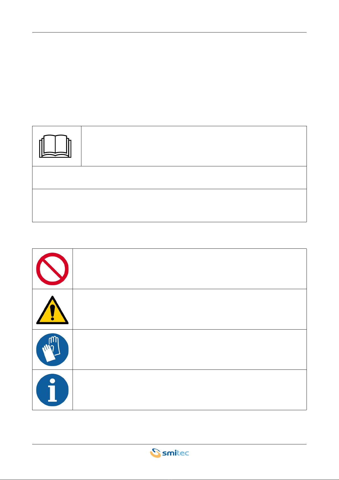
In order to make the manual consultation easier, the following symbols have been adopted:
DO NOT USE THE EQUIPMENT, NOR MAKE ANY INTERVENTION BEFORE INTE-
GRALLY READING AND UNDERSTANDING THIS MANUAL.
IN PARTICULAR, ADOPT ALL SAFETY PRECAUTIONS AND PRESCRIPTIONS INDICATED IN THIS
MANUAL.
THE EQUIPMENT CANNOT BE USED FOR PURPOSES DIFFERENT THAN THE ONES DESCRIBED IN
THIS MANUAL; SMITEC S.p.A. SHALL NOT BE HELD RESPONSIBLE FOR ANY DAMAGES, INCON-
VENIENCES OR ACCIDENTS DUE TO THE NON-COMPLIANCE WITH THESE PRESCRIPTIONS.
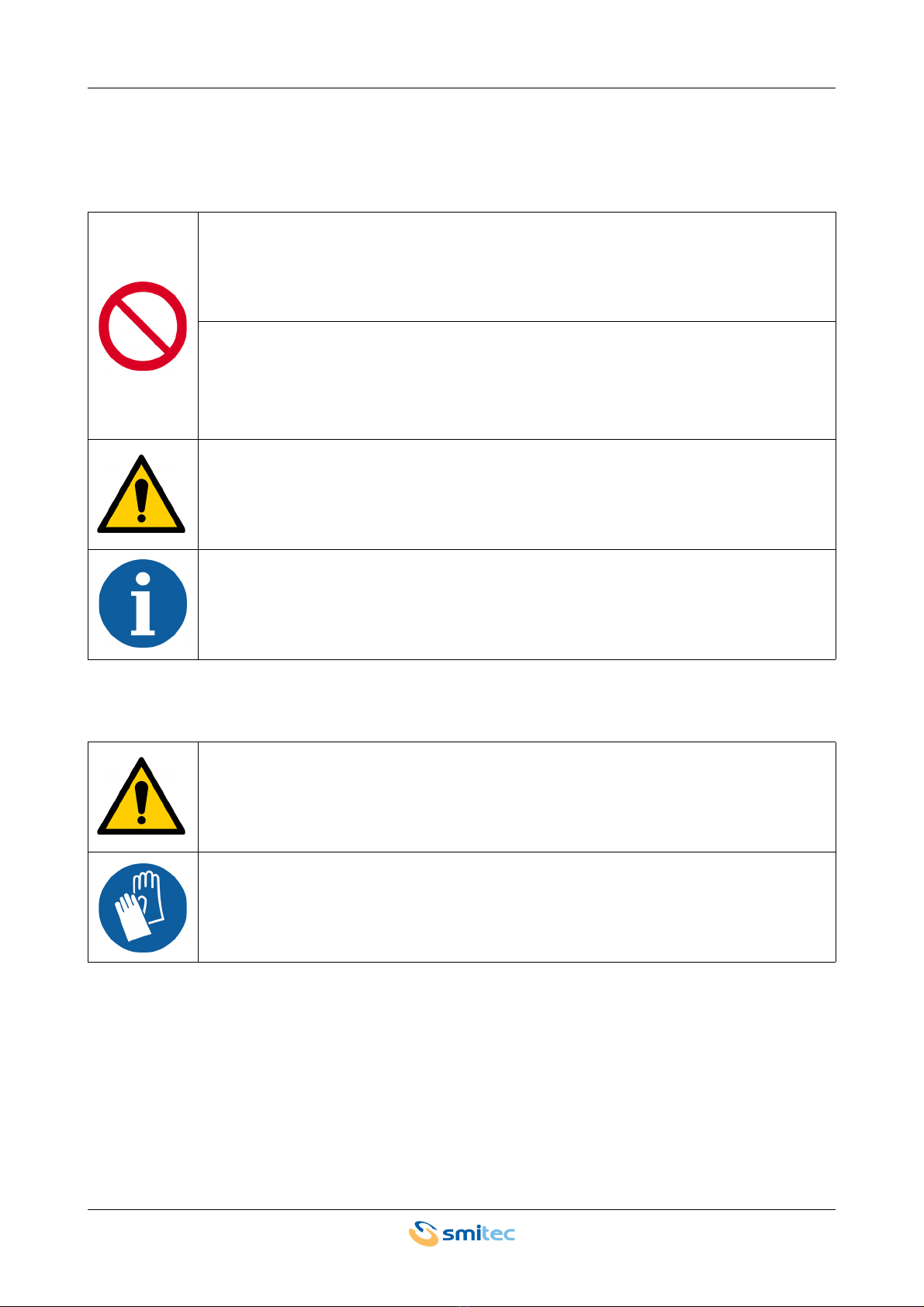
Indication of “PROHIBITED ACTION”.
The symbol "DANGER" is used when the non-respect of the prescriptions or the tampering
of organs can cause serious harm to people or things.
The symbol “USE OF INDIVIDUAL PROTECTIONS” means that protective gloves must be
worn.
Indication of “INFORMATION OF PARTICULAR RELEVANCE”.

Industrial computers POSYC 3401/3402 Installation, use and maintenance manual - EN
Ver. 1.03 5
The safety prescriptions aim at establishing a series of behaviors and obligations to be complied with, while
performing the activities described later on in this manual.
These prescriptions constitute the prescribed method of operating the device, in a way that is safe for person-
nel, equipments and environment.
Industrial computers POSYC 3401/3402 Installation, use and maintenance manual - EN
Ver. 1.03 6
3 Safety instructions
3.1 General information
3.2 Precautions during handling and assembly
Do not install or use the equipment before integrally reading and understanding this manual.
In case of difficulties of interpretation, contact SMITEC technical service.
It is absolutely forbidden to use the equipment for different purposes than the ones de-
scribed in this manual. The technical data and the drawings in this manual might have been
modified later; always refer to the latest version. All upgrades can be requested to SMITEC
S.p.A. directly.
Make sure that the personnel is qualified and adequately informed about the risks he may
run and how to avoid them.
POSYC 340X series industrial PCs can be used only after the classification of the machine
operating area and after checking the safety levels, which must correspond to the assembly
safety levels.
Use adequate tools during the assembly, in order to avoid crushing or abrasions.
Metal components and sharp surfaces may cause cuts and tears. In case of contact, be very
careful and wear the personal protection equipment.
Industrial computers POSYC 3401/3402 Installation, use and maintenance manual - EN
Ver. 1.03 7
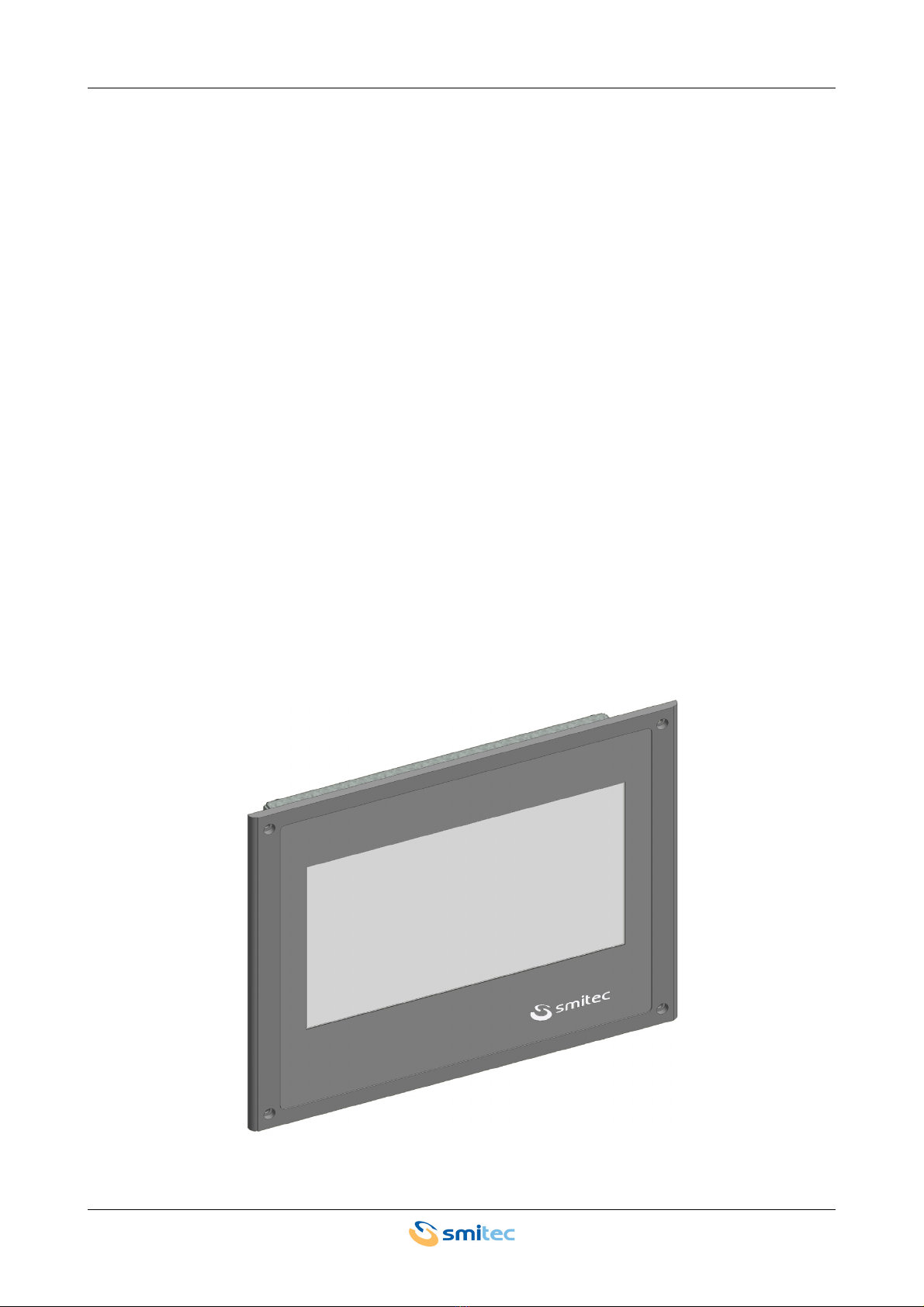
4 Product description
The POSYC is an ARM-based computer designed primarily as a human-machine interface (HMI) process-con-
troller, with I/O (depending on the model) and integrated FLXIO bus controller.
The user interface has a flat color display with a 7 “diagonal LED illuminated and a touch screen pointing sys-
tem integrated into the product.
The touch screen system offers features of robustness and ease of use, difficult to obtain with other common
pointing devices such as mouse, track-ball and mouse pad.
Being completely integrated into the appliance, it is particularly suitable even in industrial applications that re-
quire resistance to external agents such as dust, humidity, water, oils, etc., which would be harmful for standard
devices.
Since it is sufficient to exert a slight pressure with a finger on its surface to make an immediate pointing, this
system is the main “User Friendly” feature of the POSYC computer.
In order to meet the most different interfacing needs, POSYC nevertheless provides the possibility to connect
also standard input / output devices, such as keyboard, mouse, track-ball, monitor, etc.
The POSYC calculation capability is given by the ARM® Cortex® A9 i.MX6SX 1GHz processor with 1GB
DDR3L RAM memory.
The storage of data and programs on non-volatile support is entrusted to a 4GB micro SD memory.
The position of the device inside the POSYC is such that it can be extracted without opening it. The main ad-
vantage of the micro SD card is its exceptional resistance to accidental shocks and vibrations.
POSYC 340X

Industrial computers POSYC 3401/3402 Installation, use and maintenance manual - EN
Ver. 1.03 8
5 Technical data
5.1 Electrical characteristics
5.2 Electrical characteristics
The following characteristics refer to the standard POSYC computer load as supplied, without any connected
peripheral device.
All the technical information reported in this section are consistent with the hardware con-
figuration of the POSYC computer produced at the date of writing of this document. With the
aim of improving or updating the product technologically, SMITEC S.p.A. reserves the right
to change the technical features of the POSYC computer without notice.
Operating temperature 0° ÷ +50°C when operational
Storage temperature -20° ÷ +60°C when not operational
Relative humidity 0 ÷ 90% (without condensation)
Protection degree IP65 on the front (according to IEC 60529 and type 1 UL)
IP20 on the back (according to IEC 60529)
Maximum altitude 2000 m a.s.l
Main power supply voltage (PWR) 24 VDC (-15% ÷ + 20% according to IEC 61131-2) from
CLASS 2 power supply (UL)
Current consumption Max 0.40A @ 24VDC
Absorbed power Max 9.60 W
Auxiliary power supply voltage (I/O) 24 VDC (-15% ÷ + 20% according to IEC 61131-2) from
CLASS 2 power supply (UL)
Industrial computers POSYC 3401/3402 Installation, use and maintenance manual - EN
Ver. 1.03 9
5.3 Mechanical characteristics
5.3.1 Mechanical dimensions
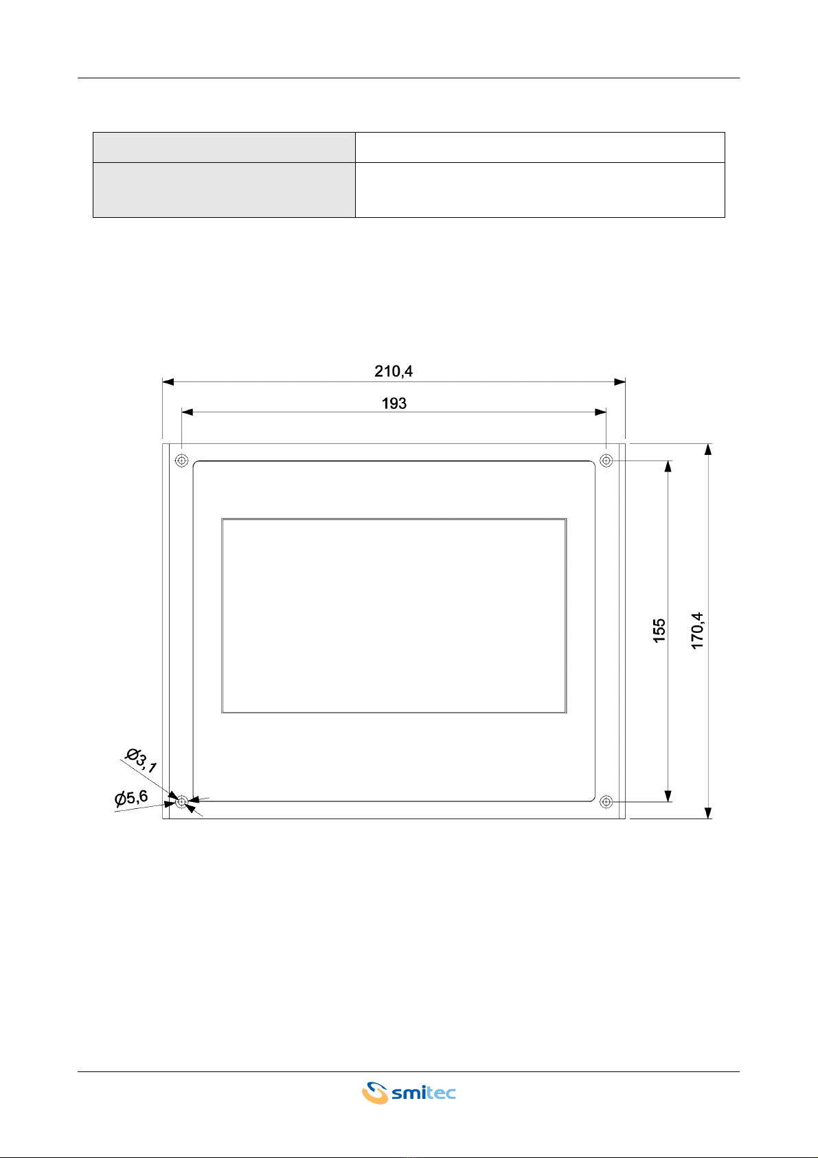
5.3.1.1 Front view
The computers Posyc 3401/3402 need to be fixed on a stable and rigid panel provided with 4xM3 metal thread-
ed hole, min. 1.5mm deep. Use 4xM3x10mm Fe/Zn (not countersunk head type) screws, min. class 8.8, tight-
ened at 1Nm.
Fixing Front panel with 4 through holes of 3.2 mm
Weight Model 3401: 0.83 kg
Model 3402: 0.78 kg
Industrial computers POSYC 3401/3402 Installation, use and maintenance manual - EN
Ver. 1.03 10
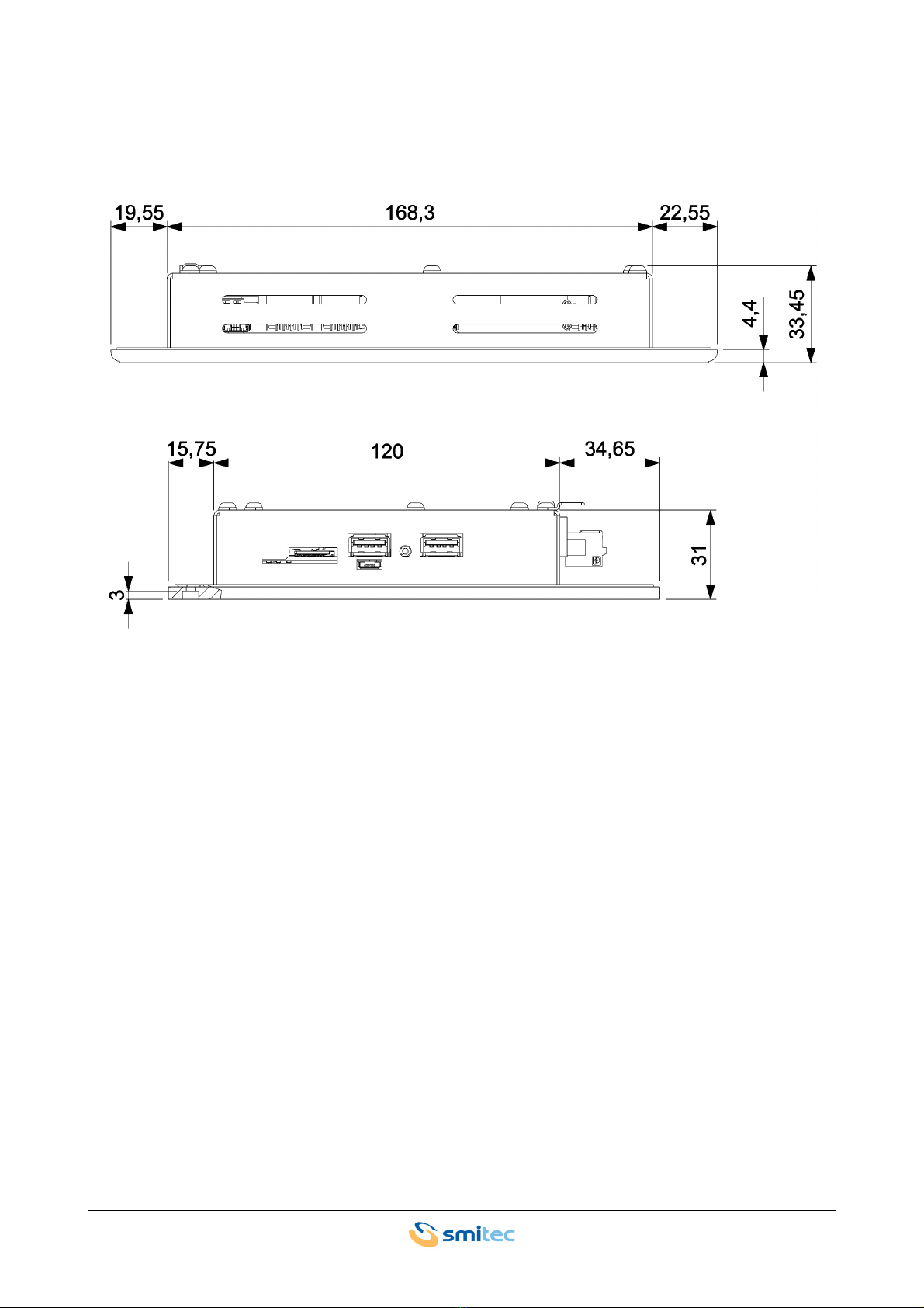
5.3.1.2 Side view
Industrial computers POSYC 3401/3402 Installation, use and maintenance manual - EN
Ver. 1.03 11
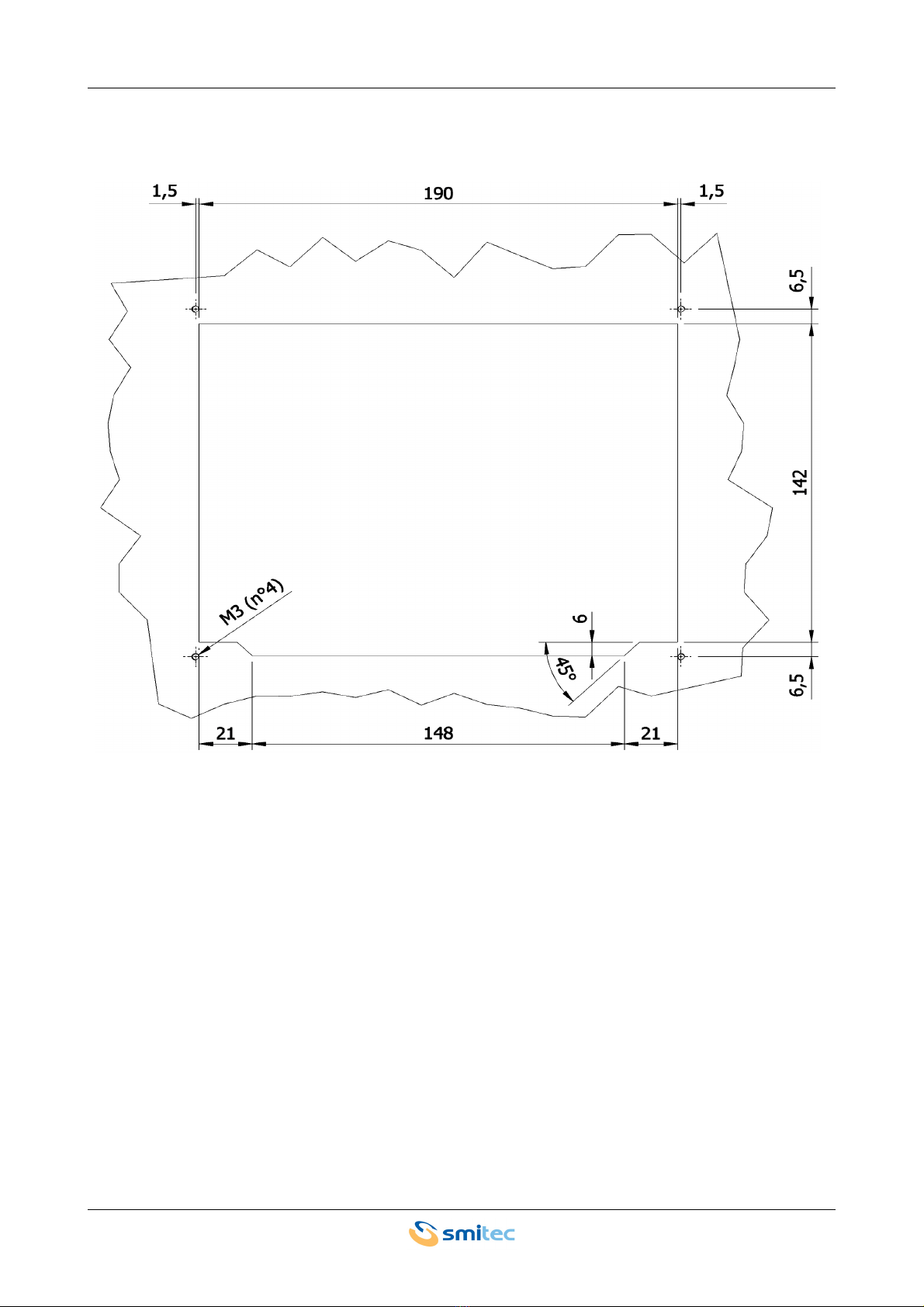
5.3.1.3 Rear view (recommended panel cut)

Industrial computers POSYC 3401/3402 Installation, use and maintenance manual - EN
Ver. 1.03 12
5.4 Hardware features
5.4.1 Basic hardware
5.4.1.1 POSYC 3401
Basic hardware with the following additions.
5.4.1.2 POSYC 3402
Basic hardware with the following additions.
The hardware whose features are described is the minimum guaranteed in the product and
functionally tested; some peripherals possibly present in addition to the purchased product
are not guaranteed neither for production continuity nor for functionality.
Processor ARM® Cortex® A9 i.MX6SX 1GHz
Memory 1GB DDR3L
Display 7 “color LED TFT, 800x480 16M with integrated touch-panel
Touch screen sensor 4 resistive wires
Side USB ports 2 x 2.0
Micro SD card 4GB with Linux operating system
Ethernet ports 2 x 10/100 Mbps
FLXIO ports 3 (isolated)
I/O
Current consumption power input (VI): 2.0A max
4 24V digital I/O (isolated): max single channel output current: 0.5A
Total current withdraw-able from the outputs (VO and I/O): 2.0A max
4 digital inputs 24V (isolated): according to IEC 61131-2 Type 1 and
Type 3
Ethernet ports 1 x 10/100 Mbps
FLXIO ports 3 (not isolated)
I/O Not present
Industrial computers POSYC 3401/3402 Installation, use and maintenance manual - EN
Ver. 1.03 13
5.5 Order codes
5.6 Accessories
The POSYC 3401/3402 industrial computers come with a power connector. The same can be ordered sepa-
rately as well as other accessories not included in the POSYC.
Below is the list of order codes.
* = Supplied with POSYC
** = Supplied only with model 3401
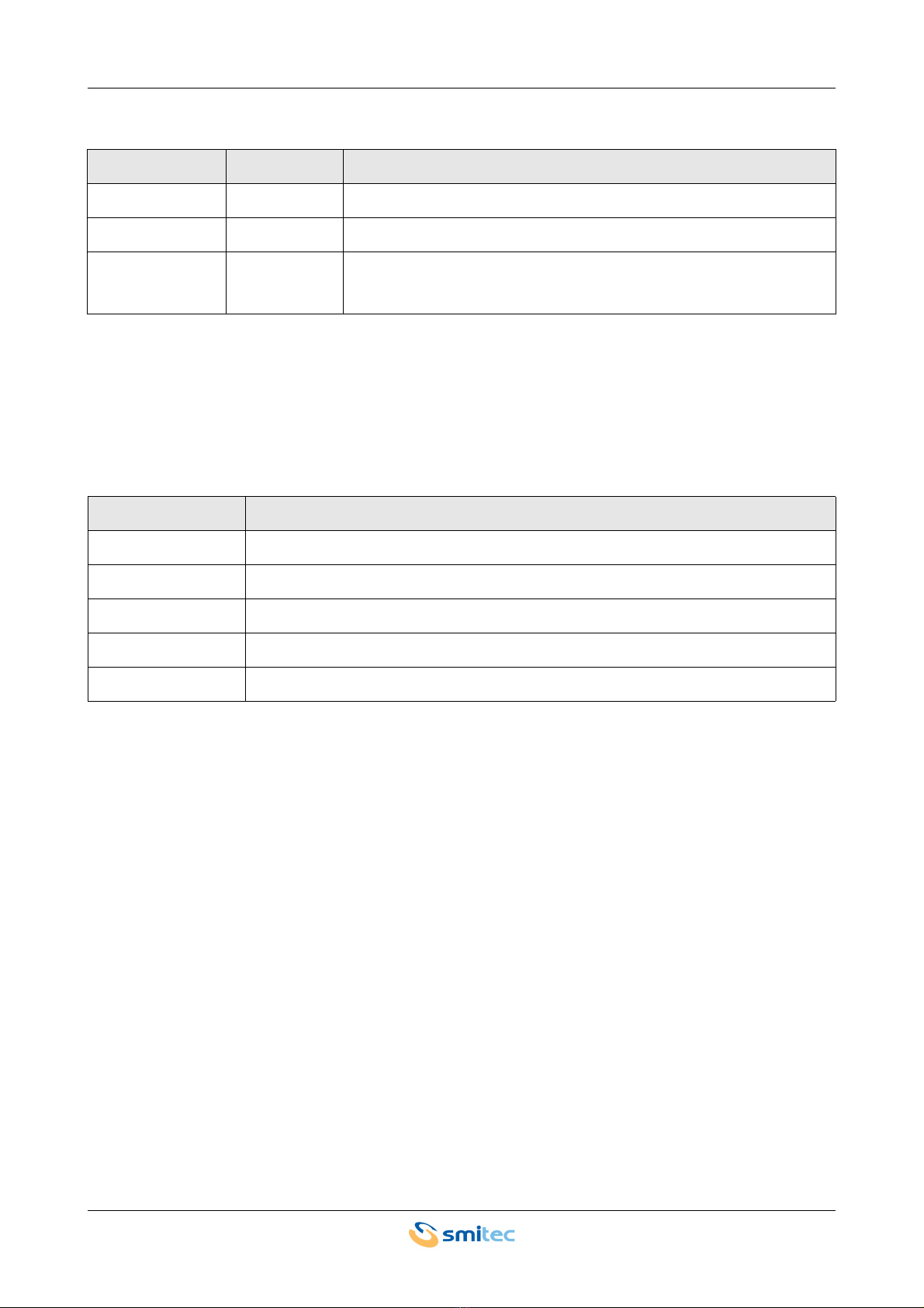
Order code Model Description
KZ010501 3401 Hardware base PC with I/O, 2 Ethernet, FLEXIO bus isolated
KZ010528 3402 Hardware base PC without I/O, 1 Ethernet, FLXIO bus not isolated
KZ010573 3402
AUDION (UL) Hardware base PC without I/O, 1 Ethernet, FLXIO bus not isolated
Order code Article
KF101074 24VDC connector (Phoenix Contact cod.1851232) *
KF101049 I/O connector (Phoenix Contact cod.1738856) **
KE050082 Micro SD flash disk, minimum class 4, 4GB capacity (with Linux operating system)
KE020040 Micro SD flash disk, minimum class 4, 4GB capacity (empty)
TB010554 CR2032 3V lithium coin cell battery *
Industrial computers POSYC 3401/3402 Installation, use and maintenance manual - EN
Ver. 1.03 14
6 Connections and LEDs
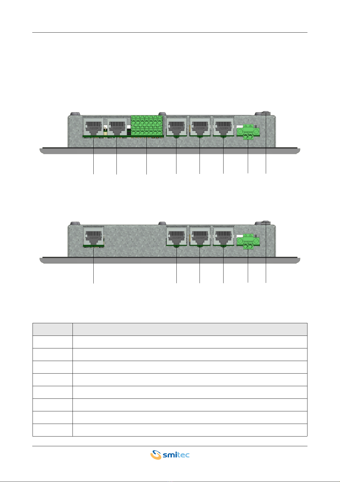
6.1 Top panel view
The following figures show the connectors on the top of the POSYC:
POSYC 3401
POSYC 3402
Name Function
PWR 24 VDC power supply connection
FE Earth protection connection
ETH 1 Ethernet communication port 1
ETH 2 Ethernet communication port 2 (only for POSYC 3401)
I/O 24V digital inputs and outputs (only for POSYC 3401)
L0 FLXIO communication port 1
L1 FLXIO communication port 2
L2 FLXIO communication port 3
ETH 1 ETH 2 I/O L0 L1 L2 PWR FE
ETH 1 L0 L1 L2 PWR FE

Industrial computers POSYC 3401/3402 Installation, use and maintenance manual - EN
Ver. 1.03 15
6.2 Side panel view
The following image shows the connectors on the side of the POSYC:
POSYC 3401/3402
Name Function
MSD Socket for micro SD card
USB AB AB type USB micro port (for SMITEC internal use only)
RESET Reset button
USB 1 Port 1 USB 2.0
USB 2 Port 2 USB 2.0
RRed LED: indication of operating status of the device (depends on the application)
O Orange LED: indication of operating status of the device (depends on the application)
GGreen LED: indication of operating status of the device (depends on the application)
MSD
USB 1 USB 2
RESET
ROG
USB AB
Industrial computers POSYC 3401/3402 Installation, use and maintenance manual - EN
Ver. 1.03 16
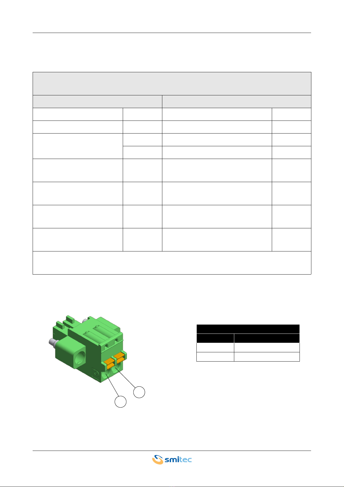
6.3 PWR connector
The connector used to power the POSYC 340X, has spring contacts to facilitate wiring of individual cables.
Connector type: Phoenix Contact FK-MCP 1,5/2-STF-3,81 (1851232) * **
Order code: KF101074
Features Conductors cross section
Connection in accordance with EN-VDE Solid min. 0,14 mm²
Rated voltage 320V Solid max. 1,5 mm²
Rated current
8A Stranded min. 0,14 mm²
Stranded max. 1,5 mm²
Insulating material PA Stranded, with ferrule without plastic
sleeve min. 0,25 mm²
Inflammability class according to
UL 94 V0 Stranded, with ferrule without plastic
sleeve max. 1,5 mm²
Stripping length 9 mm Stranded, with ferrule with plastic sleeve
min. 0,25 mm²
Screwdriver to be used for open-
ing the connections 0,6 x 3,5 mm Stranded, with ferrule with plastic sleeve
max. 0,5 mm²
*= Use only 75°C cables
**= Use only copper conductors
Supply 24VDC
Pin Signal
1 VM (24 VDC)
2GND
1
2
Industrial computers POSYC 3401/3402 Installation, use and maintenance manual - EN
Ver. 1.03 17
CAUTION
ATTENTION
Use a cable with a suitable cross-section, sized correctly according to the through-current.
A cable with a section smaller than that required may cause fire due to overheating phenom-
ena generated by the cable itself.
To ensure compliance with the EMC 2014/30 / EU directive, the length of the cables must
not exceed a length of 30 meters.
The POSYC 340X is a high-tech electronic device, sensitive to electrostatic discharge
(ESD) phenomena. Pay the utmost attention to prevent such phenomena, complying with
the provisions of the law, in order to avoid damage to the device.
Utilisez un câble de section appropriée, dimensionné correctement en fonction du courant
traversant. Un câble de section inférieure à celle requise peut provoquer un incendie en rai-
son de phénomènes de surchauffe générés par le câble lui-même.
Pour garantir la conformité avec la directive EMC 2014/30 / EU, la longueur des câbles ne
doit pas dépasser 30 mètres.
Le POSYC 340X est un appareil électronique de haute technologie, sensible aux phéno-
mènes de décharge électrostatique (ESD). Faites très attention à ce que ces phénomènes
ne se produisent pas, dans le respect des dispositions légales, afin d’endommager l’appa-
reil.

Industrial computers POSYC 3401/3402 Installation, use and maintenance manual - EN
Ver. 1.03 18
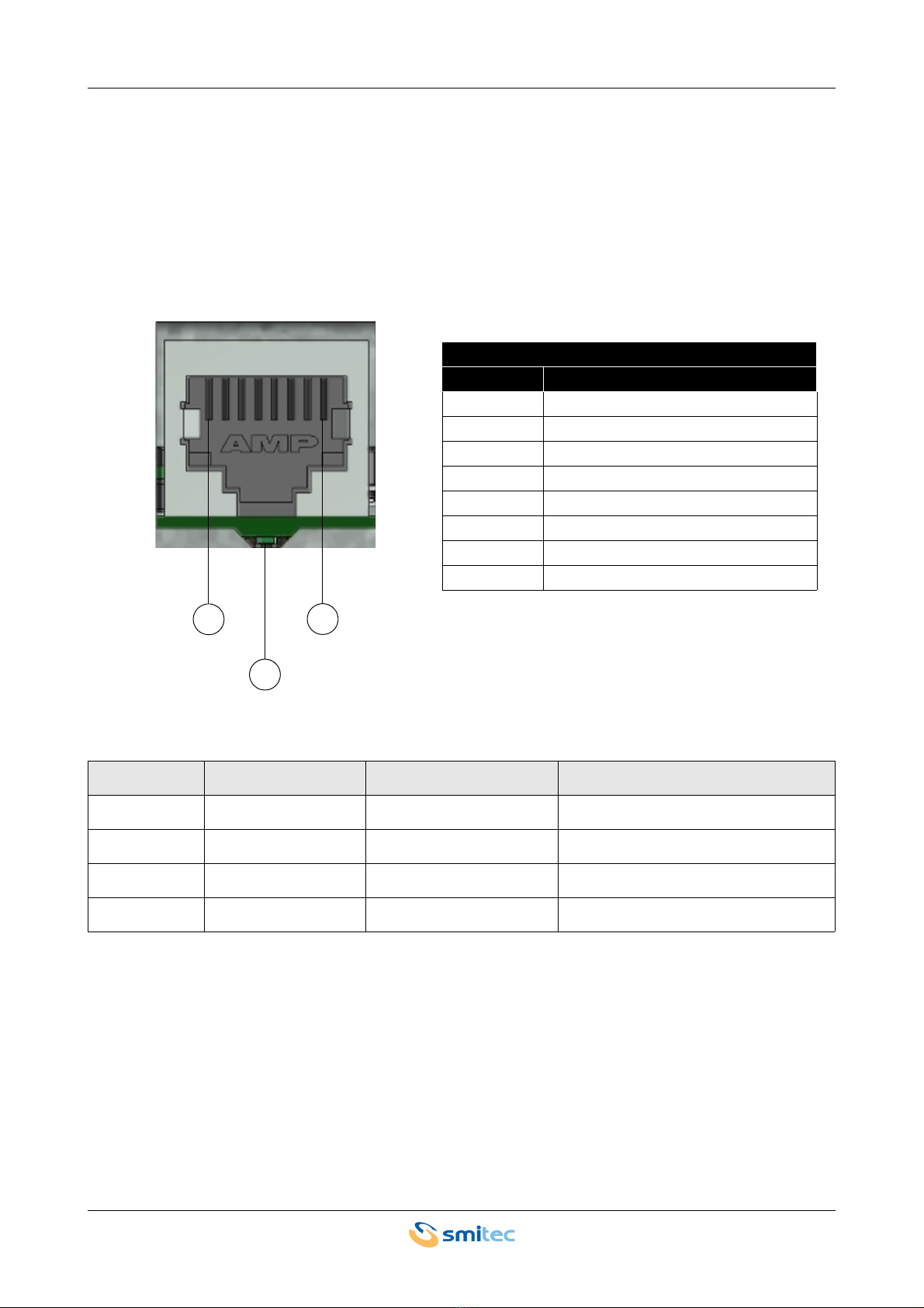
6.4 Ethernet ports
Depending on the model, there are one or two 10/100 Mbps Ethernet ports that use standard RJ45 Ethernet
connectors.
The Ethernet port has two LEDs. The first one, in green color, marked with the letter L, indicates if the door is
connected. The second, orange, marked by the letter A, indicates the state of activity of the door itself, or if the
door is communicating.
LED Color State Function
L Green OFF Not connected
LGreen ON Connected
A Orange OFF No activity
AOrange BLINK ON Communicating
LA
Industrial computers POSYC 3401/3402 Installation, use and maintenance manual - EN
Ver. 1.03 19
6.5 FLXIO port
The POSYC 3401/3402, are equipped with three FLXIO doors; the ports are isolated in the model 3401 unlike
the model 3402. This proprietary field bus is based on an RS485 electrical interface and allows a reliable real-
time control of complex applications.
The connections are made via the RJ45 connectors; the following illustration shows the pinout of one of the
connectors and the behavior of the LED (S).
This fieldbus requires a minimum CAT 5 type shielded cable, headed with RJ45 connectors.
Refer to the FLXIO and FLXMOD integration manual (DK400076) for using these buses.
LED Color State Function
S Green Slow flashing (1Hz) Initialization of the bus
SGreen OFF Absent communication
S Green ON Communicating
SGreen Fast flashing (5Hz) Communication error
FLXIO port
Pin Signal
1DATA+
2 DATA -
3GND
4NC
5NC
6 Self-addressing service
7 Reserved
8 Reserved
18
S

Industrial computers POSYC 3401/3402 Installation, use and maintenance manual - EN
Ver. 1.03 20
6.6 I/O connector
The connector used for the wiring of the digital I / O of the POSYC 3401/3402 is detachable and has spring-
loaded contacts to facilitate the wiring of the individual cables:
Connector type: Phoenix Contact FMCD 1,5/ 7-ST-3,5 (1738856) * **
Order code: KF101049
Features Conductors cross section
Connection in accordance with EN-VDE Solid min. 0,2 mm²
Rated voltage 160V Solid max. 1,5 mm²
Rated current
8A Stranded min. 0,2 mm²
Stranded max. 1,5 mm²
Insulating material PA Stranded, with ferrule without plastic
sleeve min. 0,25 mm²
Inflammability class according to
UL 94 V0 Stranded, with ferrule without plastic
sleeve max. 1,5 mm²
Stripping length 10 mm Stranded, with ferrule with plastic sleeve
min. 0,25 mm²
Screwdriver to be used for open-
ing the connections 0,6 x 3,5 mm Stranded, with ferrule with plastic sleeve
max. 0,75 mm²
*= Use only 75°C cables
**= Use only copper conductors
This manual suits for next models
1
Table of contents


