SMT 600REY User manual
Date Manufactured:
__________/__________/__________
600 Series
REY ____________________
600 Series
WCY ____________________
2000 Series
REY ____________________
SMT Central Systems
600REY 600WCY 2000REY
Owner’s Manual
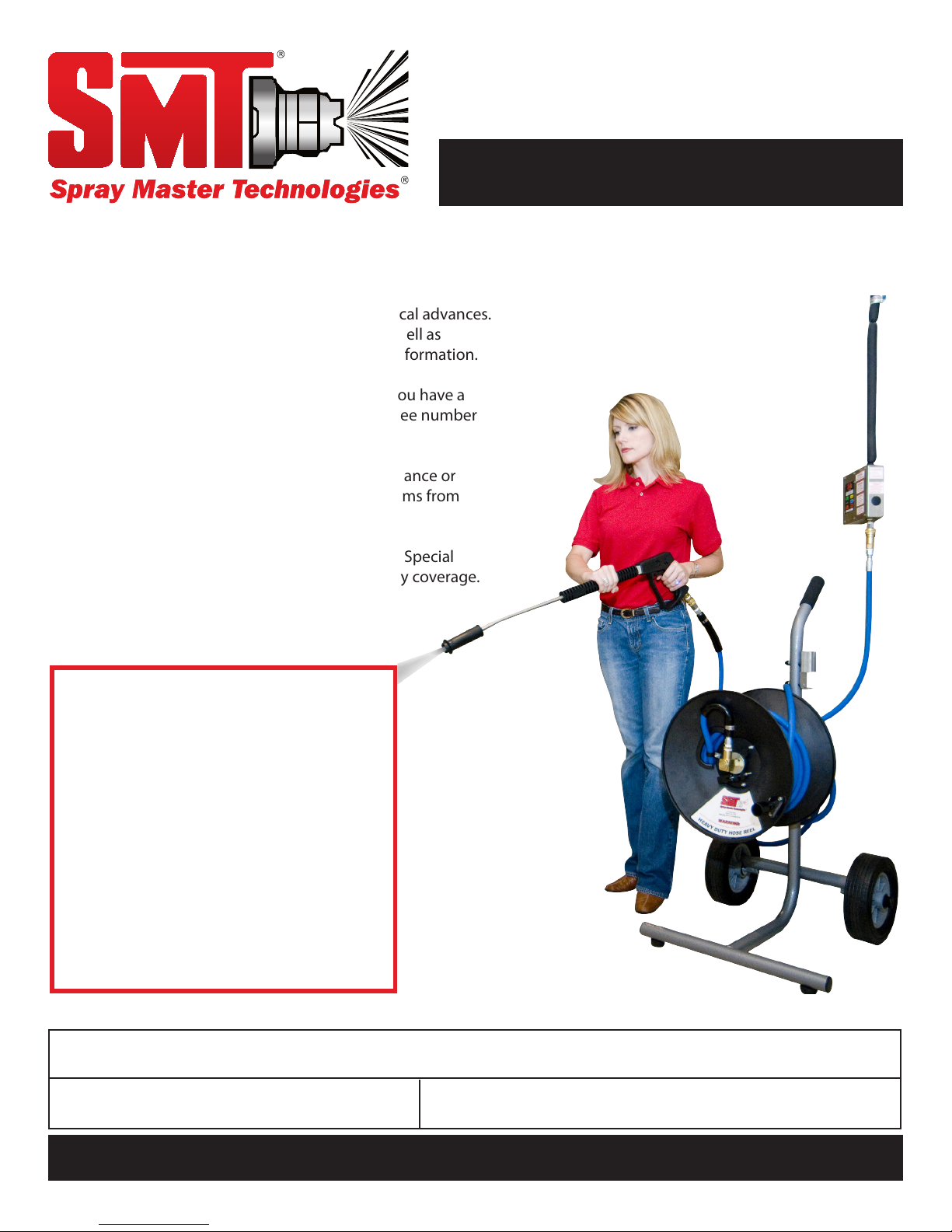
You have just purchased the best spray washer on the market
today. It incorporates the very latest in technological advances.
To assure you the best and safest performance as well as
longest equipment life, please read the enclosed information.
After reading the material in this manual, should you have a
service problem or need help, please call our toll free number
1-800-548-3373 or (479) 636-5776.
TERMS: All parts will be shipped with check in advance or
C.O.D. Commercial accounts are allowed 15 day terms from
date on invoice with approved credit.
FREIGHT: All freight will be paid by the customer. Special
consideration will be given to items under warranty coverage.
NOTE: Specications found in this manual subject to change without notice.
FOR COMMERCIAL USE ONLY
IMPORTANT DOCUMENT - DO NOT DISCARD
Serial Number: Date Shipped:
spraymastertech.com
SMT WARRANTY – LIMITED Eective November 1, 2008
PARTS -SMT warrants parts for wall mounted and rack mounted 600 series and 2000 series machine to be free from defects in material or workmanship for a period
of 2 years from the date of purchase from date of shipment from factory (if proof of purchase is missing) to the original purchaser excluding items listed below.
SMT warrants parts for all other machines, wall mounted 1100 series machines and all portable machines to be free from defects in material or workmanship for
a period of 1 year from the date of purchase (from date of shipment from factory if proof of purchase is missing) to the original purchaser excluding items listed
below. This warranty is limited to repairing or replacing products to the original purchaser, which manufacturer’s investigation shows were defective at the time of
shipment by the manufacturer. All products subject to this warranty shall be returned F.O.B. Spray Master Technologies - Rogers, Arkansas for examination, repair or
replacement.
The warranty set forth herein is in lieu of all other warranties, expressed or implied, including without limitation any warranties of merchantability or tness for
a particular purpose and all such warranties are hereby disclaimed and excluded by the manufacturer. The manufacturer shall not be liable for any further loss,
damages, or expenses, including incidental or consequential damages, directly or indirectly arising from the sale or use of this product.
ITEMS VOIDING WARRANTY- This warranty is subject to the following conditions and limitations. The following voids all warranty claims on Spray Master
Technologies products: Abuse, misuse, using excessive hot water temperatures - exceeding 120 degrees Fahrenheit (49 degrees Celsius), hard water conditions,
using bleach as an injected chemical, failures caused by incorrect installation or failure to correctly wire the system at the electrical source.
EXCLUDED ITEMS- The following items are excluded: SPRAY GUNS, WANDS, HOSES, NOZZLES, HUMMER JET SR. & JR. CASTERS AND HANDLES. These items are
covered by the above warranty for 90 days from the date of purchase for defects in materials or workmanship.
LABOR - to repair or replace defective components shall be covered for a period of 1 year from date of purchase (90 days on excluded items), proof of purchase is
required.
www.spraymastertech.com
Phone: 479.636.5776 • Fax: 479.636.3245 • 115 E. Linden • Rogers, Arkansas 72756 USA
SMT-WARRANTY-CS-102808-EN Specications are subject to change without notice Printed in the U.S.A.
Water
Flow: 4 gallons per minute (600 & 1100 series) or 5 gallons per
minute (2000 series) @ 30 PSI minimum.
Temperature: 120° F maximum, 120° F recommended.
Connection: Hose Bib.
Electrical
2000 Series: 208-230V/30Amp (single phase) dedicated circuit with GFCI circuit breaker in main panel and service disconnect at pump. 600 & 1100 Series:
208-230V/20Amp (single phase) dedicated circuit with GFCI circuit breaker in main panel and service disconnect at pump.
Service Requirements
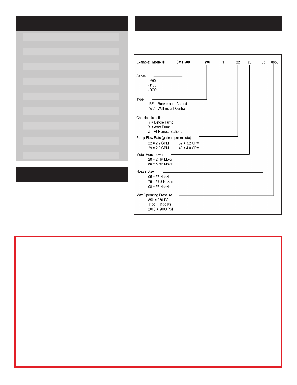
The complete model number located on the serial number label identies
the series, type and operating specications of the system.
Model Identication & Specications
Warranty 2
Model Identication & Specications 2
Service Requirements 2
Warranty 2
Warning Labels 3
Risk of Fire, Electric, or Personal Injury 3
Grounding & GFCI 3
Returned Goods Policy 3
Operating Instructions 4-5
User Maintenance 5
Sensors 6
Service 6
Features 6
Moving & Storage 6
Chemical Metering Instructions 6
SMT Wiring Schematics 7
SMT Wiring System 8
Table of Contents
2

Receiving
Damage: Report any damage to the shipping
carton or contents to the freight carrier. File a claim
with the carrier within 10 days if damage is evident.
The manufacturer is not responsible for damage to
the equipment caused by the freight carrier.
Package Contents: Carefully check the contents
of the shipping cartons to ensure the contents
agree with the packing list. If items are missing
or if you have any questions, please call our
customer service department at (800) 548-3373
or (479) 636-5776.
Warning Labels
These "WARNING" labels are axed to your
system for all operators to read. If they have
been removed or are illegible, please call
1-800-548-3373 for replacement.
Note: Labels on this page are not to scale.
Risk of Fire, Electric Shock or Personal Injury
IMPORTANT SAFETY INSTRUCTIONS
WARNING - When using this product, basic precautions should always be followed, including the
following:
• Read all the instructions before using the product.
• To reduce the risk of injury, close supervision is necessary when a product is used near children.
• Know how to stop the product and bleed pressures quickly. Be thoroughly familiar with the controls.
• Stay alert - watch what you are doing.
• DO NOT operate the product when fatigued or under the inuence of alcohol or drugs.
• Keep operating area clear of all persons.
• DO NOT overreach or stand on unstable support. Keep good footing and balance at all times.
• Follow the maintenance instructions specied in the manual.
• NEVER look directly into a nozzle. Always release the pressure in the high pressure hose by
opening the spray gun after machine is shut o.
• NEVER allow your unit to run at a pressure above its “maximum pressure while spraying” as
documented in this manual for your model number.
• NEVER re-adjust the unloader valve if it has been set by the factory.
• NEVER turn the unloader adjusting nut whereby the unloader opening pressure exceeds
100 PSI above“maximum pressure while spraying.”
WARNING - Risk of injection or injury -
DO NOT directly discharge stream at persons.
SAVE THESE INSTRUCTIONS
Ground Fault Circuit Interrupter (GFCI) Protection
A GFCI is a safety device that protects the operator from electrical shock hazards by disconnecting
power from a circuit to a load when a potentially dangerous condition occurs.
NEVER BYPASS A GFCI. Find out the cause or reason why the GFCI opened the circuit. This may
require the services of a qualied electrician. Do not attempt any electrical repairs yourself.
This product shall be permanently connected to a dedicated power supply circuit protected by
a Ground Fault Circuit Interrupter. This product shall be connected through a service disconnect
located at the pump.
Grounding
This product must be connected to a grounded,
metal, permanent wiring system; or an equipment-
grounding conductor must be run with the circuit
conductors and connected to the equipment-
grounding terminal or lead on the product.
Installation
Installation instructions are contained in
a separate manual that is provided with
your system.
Returned Goods Policy
Any item returned for warranty consideration or for credit must have a RETURN AUTHORIZATION
NUMBER. Call our Customer Service Department and discuss the nature of your request. Please
note that all items returned must be returned F.O.B. Rogers, Arkansas. No collect or C.O.D.
shipments will be accepted unless prior arrangements with our Customer Service Department
have been made. A restocking fee may be applied to items for credit that are not under warranty.
To reach our Customer Service Department call (800) 548-3373 or (479) 636-5776, or write to
Spray Master Technologies®, 115 E. Linden St., Rogers, Arkansas 72756.
3

Operating Instructions
Preparation For Use
• Oil level: The red dot at the center of the clear sight glass on the end of the pump indicates the proper oil level when the pump is o. Check the
oil level in the pump at least once each week. Change the initial oil ll after 50 hours running time. Thereafter, change oil every 3 months or 500
hours of operation.
• Water supply: Check the water supply to the system. Verify that the valve is fully open, the water temperature is less than 120° F, and the lter is
not blocked.
• Chemical supply: Ensure there is adequate chemical in the chemical supply containers. Inadequate chemical supply will reduce cleaning
eectiveness, and may cause a loss of pressure, pump cavitation, excessive wear on the pump seals and shortened pump life.
• Hose and spray gun: Check the hoses and spray gun for leaks and other damage. Leaks will cause lower pressure, pump pulsation and reduced
operating life of the pump and unloader.
Accessory Operation
Spray gun: The spray gun assembly is connected by quick-connect ttings to the output end of the high-pressure hose. Hold the spray gun rmly
with both hands. Operate the spray gun by squeezing the gun trigger while directing the hi-pressure spray toward the surface or object to be
cleaned.
Dual nozzle selector: The dual nozzle selector is located on the nozzle end of the spray gun and used to select either low or high-pressure spray.
Selection of the desired nozzle must be made while the spray gun trigger is released. To select the low pressure nozzle, rotate the spray gun 90°
counter-clockwise so that the spray gun handle is parallel to the ground with the hose connection extending to the operator’s right, then squeeze
the spray gun trigger. To select the high-pressure nozzle, rotate the spray gun 90° clockwise so that the spray gun handle is parallel to the ground
with the hose connection extending to the operator’s left, then squeeze the spray gun trigger. Once the nozzle has been selected and the spray gun
trigger held open, the spray gun can be rotated and aimed in any direction without aecting nozzle selection.
Vari nozzle: The vari nozzle is used to select low or high pressure, and to adjust the spray pattern. Selection of the high or low pressure is made by
moving the black body of the nozzle toward or away from the gun handle. For high pressure, pull the black nozzle-body rmly toward the spray gun
handle. To select low pressure, push the black nozzle-body rmly away from the spray gun handle. The spray pattern can be varied from a fan spray to
a zero degree stream. To vary the spray pattern at the nozzle, twist the black nozzle-body for the desired spray pattern.
Warning: Pressurized spray may cause personal injury or injection. Never adjust vari nozzle while spray gun is in operation.
Tornado nozzle: The tornado nozzle is a powerful tool that easily removes the most dicult dirt and grime. The nozzle directs a high-pressure,
rotating, zero-degree stream in a high speed, close circular pattern. The circular pattern allows for maximum coverage with the zero-degree stream.
Simply aim the nozzle at the surface to be cleaned and squeeze the spray gun trigger.
Trap shooter: The Trap Shooter is used to open up clogged drains. To use the trap shooter, connect it to the SMT pressure cleaning system, insert the
trap shooter nozzle as far into the blocked drain as possible and squeeze the trigger on the trap shooter gun.
Warning: Pressurized spray may cause personal injury or injection. Never operate the trap shooter without the nozzle fully inserted into the
drain. The trap shooter nozzle sprays in both the forward and reverse directions.
Remote station: The Remote Stations are permanently connected to the main pump system through stainless steel tubing and shielded control
cable. The remote station provides remote operation of the pump and chemical injection systems from up to ten remote locations. Only one remote
can be operated on each pumping system at a time. In addition, the Remote Station provides a quick connect access to the pressurized water at each
remote location. The lights on the remote station’s panel indicate the status of the system to the operator.
There are ve controls on the remote station touch-pad.
ON - turns the pump on
OFF - turns the pump o
SOAP- enables the Soap Injection feature while the pump is operating
SANITIZE- enable the Sanitize Injection feature (if equipped) while the pump is operating,
RINSE - disables both Soap and Sanitize functions.
READY - lamp on the remote station indicates that the system is available for use, and not in use at any other remote station.
Attempting to operate two remotes simultaneously, will reduce pressure and water ow to both remotes. All other remote station controls are
disabled when an operator turns the system on at any one remote station. This prevents operation interference from the other remotes.
Hose reel: Hose reels for use with a central system are equipped with an umbilical hose and a quick connect to allow for connection to the remote
station port. Hose reels are available as portable or stationary wall-mounted units, with 3/8” hose capacities of 75 to 200 feet. Connect the hose reel
umbilical hose to the remote station with the quick coupling provided. Connect the spray gun or other accessory to the output hose on the hose
reel. Reel o minimum amount of hose to reach the area to be cleaned. Excessive hose in the working area is a trip-hazard and should be avoided.
Manually rewind hose after use.
Hummer Jet™Sr.: The Hummer Jet Sr. is a at surface cleaner for use with SMT 2000 series pressure cleaning systems. High-pressure spray is directed
by two high-pressure nozzles rotating at high speed just inches above the surface to be cleaned. Connect the Hummer Jet Sr. to the high-pressure
hose and set the control valve to “OFF”. Turn the pumping system “ON”, open the control valve fully. Move the Hummer Jet Sr. over the surface to be
cleaned while the high-pressure blasts away the dirt and grime.
WARNING: Pressurized spray may cause personal injury or injection. Never place hands or feet under the Hummer Jet Sr. body while it is in operation.
Keep all four wheels of the Hummer Jet Sr. in contact with the surface being cleaned during operation.
4

Operating Instructions
Hummer Jet Jr: The Hummer Jet Jr. is a at surface cleaner for use with SMT 600, 1100, and 2000 series pressure cleaning systems. High-pressure
spray is directed by two nozzles rotating at high speed just inches above the surface being cleaned. The Hummer Jet Jr. is equipped with a detachable
caster ring that permits using the Hummer Jet Jr. with or without casters. The caster ring is easily removed by squeezing the spring-loaded retainer
clip and lifting the Hummer Jet out of the ring. The caster ring is re-attached to the Hummer Jet by placing one edge of the Hummer Jet Jr. under
the stationary tab inside the caster ring and pressing down gently until the spring loaded retainer clip captures the opposite side of the Hummer Jet
Jr. Casters provide ease of movement for the Hummer Jet Jr. while detaching the casters allows for cleaning in close quarters and closer to walls and
other objects. Connect the Hummer Jet Jr. to the hose by mating the quick connects. Turn the pumping system “ON” and squeeze the trigger on the
Hummer Jet Jr. handle. Move the Hummer Jet Jr. over the surface to be cleaned.
WARNING: Pressurized spray may cause personal injury or injection. Never place hands or feet under the Hummer Jet Jr. body while it is in
operation. Keep the Hummer Jet Jr. in complete contact with the surface being cleaned during operation.
System Operation
The “READY” lamp on each remote station is the system status indicator. Check the“READY”lamp on any remote station to ensure that no other user
is operating the system. An illuminated “READY”lamp indicates that the system is not in use and is available for operation. An extinguished “READY”
lamp indicates that another user is cleaning and the system is not available. All other lamps on the remote station (ON, OFF, SOAP, RINSE, SANITIZE),
apply only to that remote station and only when it is in control of the system.
Step 1: Connect the high-pressure hose or hose reel to the selected remote station with the quick-connects.
Step 2: Connect the spray gun to the high-pressure hose with the quick-connects.
Step 3: Hold the spray gun rmly with the spray gun trigger released.
Step 4: Press the ON button on the remote station touch-pad. The “ON”lamp will illuminate on the remote station, the pump will operate and the
system will pressurize.
Step 5: For Soap application, press the SOAP button on the remote station touchpad. The SOAP lamp will illuminate on the remote station and soap
will be injected into the high-pressure spray. It may require operation for one minute for soap to appear at the spray gun.
Step 6: Grasp the spray gun rmly with both hands, direct the spray gun at the surface or item to be cleaned and squeeze the spray gun trigger.
WARNING! Risk of electrocution. Do not spray energized electrical equipment or electrical outlets.
WARNING! Risk of injection or injury - Do not direct discharge stream at persons.
Step 7: For Rinse application, press the “RINSE” button on the remote station touch-pad. The Rinse lamp will illuminate on the remote station. It may
require operation for one minute for the chemical to be purged from the system and clean water to ow out the spray gun.
Step 8: To apply Sanitizer (if your system has this feature), press the “SANITIZER”button on the remote station. The Sanitizer lamp will illuminate on
the remote station and sanitize solution will be injected into the high-pressure spray. It may require operation for one minute for sanitizer to
appear at the spray gun.
Step 9: Rinse the surface or item to be cleaned thoroughly.
Step 10: Disconnect and store hose, hose reel and spray gun.
NOTE: For systems with down-stream chemical injection (identied by an X or Z in the model number), chemical is injected on low pressure only
and metered with a chemical metering knob. To select chemical injection, operate the spray gun on low pressure. To rinse, operate the spray gun on
high pressure.
User Maintenance
Oil - Add oil as necessary to keep the oil level at the center of the red dot on the oil level sight glass. Check the oil level with the pump "OFF". Use ISO
68, 30 weight non-detergent hydraulic oil only. Change the initial oil ll after 50 hours running period. Thereafter, change oil every three months or
500 hours of operation.
Filters - Replace lter element in the water supply lter assembly as necessary to ensure free ow of clean water to the pumping unit. Clean or
replace the bulb screen lter in the oat-tank as necessary to permit unrestricted ow to the input of the pump.
Chemical injection system servicing - Clean the chemical foot screens with warm water to remove chemical build up that will restrict chemical ow.
Remove the chemical pickup tubes from the chemical containers and submerse them in a container of warm water. To ush the chemical solenoids,
submerse the chemical pickup tubes in warm water and operate the spray gun at a remote station for several minutes with each chemical selected.
Chemical metering - To adjust the chemical mix ratio, use a 1/16”allen wrench to turn the needle-valve set screw located between the mounting
screws on the bottom of the chemical solenoids. Chemical metering can be adjusted to the desired mix ratio by following the instructions on the
chemical metering chart on page 6 of this manual.
Note: All user replaceable items are available from Spray Master Technologies® by calling our customer service number at 1-800-548-3373 or (479) 636-5776.
Winterization: Warning…Outside remotes stations can be damaged during prolonged freezing weather. Using the SMT winterizing hose accessory
(SKU # 300-2592), please follow Winterization Procedure document (300-0237) to drain water from the remote stations during winter months. For
additional information call our Service department at 800-548-3373.
5

Sensors
Water supply sensor (oat switch/pressure switch): SMT 600 and 2000
series pumps are equipped with a water supply oat switch in the tank
that will disable the system should the water supply to it be interrupted.
SMT 1100 series pumps are equipped with a water supply pressure switch
that will disable the system should the water supply be interrupted.
Water temperature sensor (thermal limit switch): This product is
equipped with a water supply sensor that will disable the system
should the water supply temperature exceed 120° F. Excessive water
temperature will reduce the life of the pump.
Chemical inhibit sensor (ow switch): All SMT 600 and 2000 series
central systems are equipped with a chemical inhibit ow switch that
disables the chemical injection solenoids when the spray gun is closed
and water is being recirculated back to the oat tank. This feature is
required to prevent chemical introduction into the tank.
Features
Anti-siphon/anti-backow: The oat tank and oat valves provide anti-
siphon/anti-back ow protection for the potable water supply system,
and is approved for use by the City of Los Angeles, California (one of the
strictest standards in the country).
Line pressure release: The line pressure release feature dumps the
pressure in the system any time the pump is turned o to allow hoses,
spray guns and other accessories to be connected and disconnected. It
also saves time and steps by eliminating the need to manually open the
bleeder valve to release pressure.
Bleeder valve: The bleeder valve provides a service port for the system
and manual system pressure release.
Unloader: The unloader feature removes the pressurized load from the
pump and motor when the user is not spraying with the spray gun. This
prolongs the life of the pump and motor.
Moving & Storage
Service
Operator troubleshooting - If your system does not operate correctly,
check the following items to ensure that the problem is not external to
the system.
• Main circuit breaker is reset and 24V AC lamp in Master Control Panel
is illuminated.
• Water supply to the system is fully open, hose is not kinked and lter
is clean.
• Water supply temperature to the pump is less than 120°F.
• Bleeder valve on wall next to pump is fully closed.
• Chemical pickup tubes are fully submersed in adequate chemical supply.
Technical Trouble shooting - If a problem occurs, please refer to the
"Diagnostic and Maintenance Chart" in the Express Service Manual.
If the problem is not resolved, then please call our toll free customer
service number 1-800-548-3373 or (479) 636-5776.
Spray Master Technologies® has a nationwide service network. If the
conditions listed above are correct and the system still does not operate
properly, call the SMT Service Department, 1-800-548-3373 or (479)
636-5776, for assistance.
Moving equipment and accessories: Avoid dragging hoses, guns and
accessories across the ground or oor during movement to prevent
damage and prolong the life of the equipment.
Storage:
• Flush the pump, gun and hose with rinse water to clean out any
chemical residue in the system.
• Wipe down your pressure washer and neatly store all hoses, cords
and accessories.
• If the pressure washer is to be stored for more than three months,
change the oil upon re-entry into service.
• Properly store equipment so that it does not present a falling or trip
hazard.
• Store equipment and accessories in an area that is protected from
freezing. Equipment and accessories could hold water after use and
may be damaged when it freezes.
Chemical Metering Instructions
One gallon equals 128 ounces
CHEMICAL DILUTION:
Ounces of Water per Ounce of Chemical
Note: Do not use bleach as the injected
chemical. Any such use of bleach will
void the warranty on your machine.
To calculate and adjust the chemical dilution for a Spray Master Technologies cleaning system, follow the steps below:
1. Find your pump GPM rating on the left-hand side of the chart.
2. Follow the row selected in Step 1 to the right and nd the column with the approximate “Dilution Ratio”specied for the chemical to be used. (If
the exact dilution ratio specied for your chemical is not listed, interpolate between the two nearest ratios on that row.)
3. From the mix ratio identied (or interpolated) in step 2, move to the top of the column to determine the“Chemical Injection: Ounces per Minute”
to be injected. EXAMPLE: A 3 gallon per minute (GPM) pump used to apply a chemical requiring a mix ratio of 128:1 (1 ounce per gallon) you
will need to inject 3 ounces of chemical during a period of 1 minute.
4. Fill a measuring cup (graduated in ounces) with the chemical to be injected and submerge the chemical pick-up tube with foot screen into the chemical.
5. Turn the pump on and set it to inject the chemical.
6. Adjust the chemical metering device so that the ounces of chemical calculated in Step 3 above is drawn from the measuring cup during a period
of one minute.
NOTE: Check chemical metering regularly to ensure accurate chemical dispensing.
6
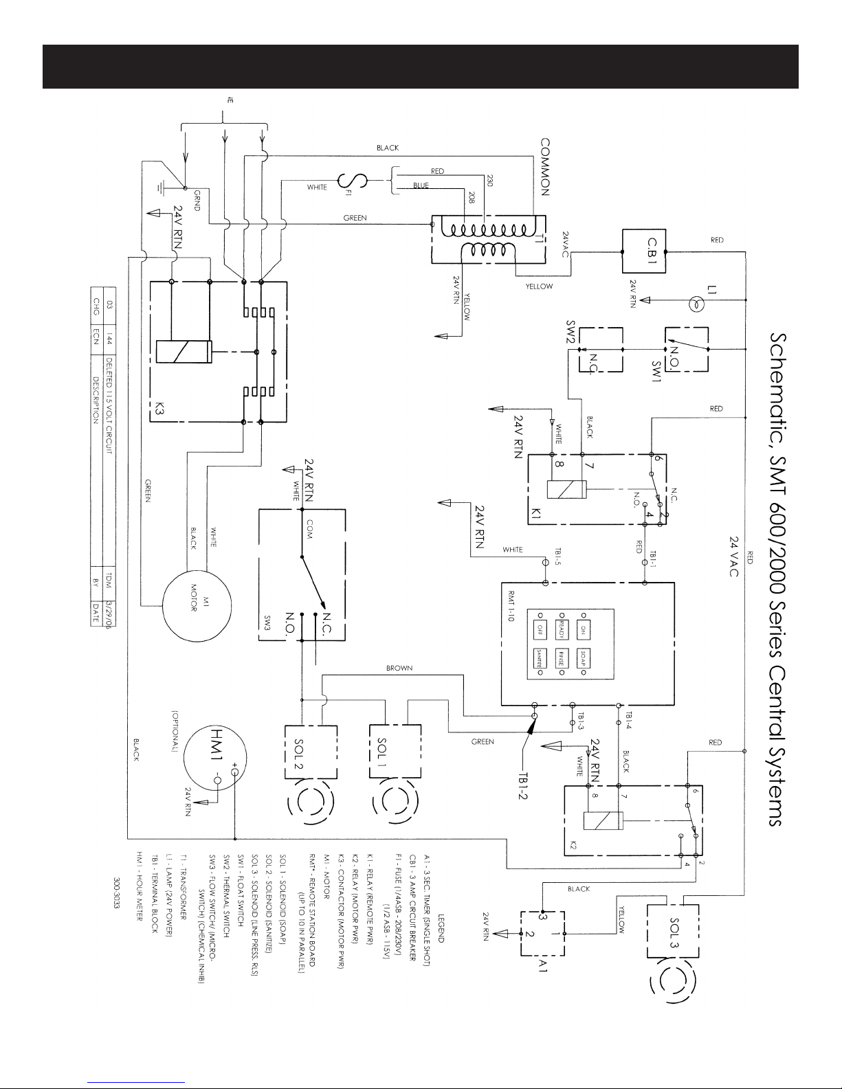
SMT Wiring Schematics
7

SMT Wiring System
SPRAY MASTER TECHNOLOGIES®
A product line of Assembled Products Corporation
115 E. Linden Street, Rogers, Arkansas 72756
479-636-5776 • 800-548-3373
spraymastertech.com
SMT-CSYS-OM-140421-EN Price and specifications are subject to change without notice . Printed in the USA.
Other manuals for 600REY
1
This manual suits for next models
2
Table of contents
Popular Pressure Washer manuals by other brands

Black & Decker
Black & Decker BCPC20 Original instructions

DeVillbiss Air Power Company
DeVillbiss Air Power Company Water Driver D28921 Operation manual

Frank
Frank FC 711 M operating instructions

Champion Power Equipment
Champion Power Equipment 71320 Owner's Manual and Operating Instructions

North Star
North Star M157115C.2 owner's manual

Homelite
Homelite UT80522G Quick reference guide


