Smyth Research Realiser A16 User manual

The Realiser A16 is defined by its firmware, which is updated from time to time with refinements and new features.
Likewise the manual is updated to conform with new firmware, and to provide additional information.
Current firmware and the current manual are available on the Smyth Research website at: www.smyth-research.com/downloads
Please check regularly for firmware and manual updates and keep both current. There may be significant differences between the
operation described here and that for other firmware versions.
Realiser A16 Manual
Mathew Kane
Manual v0.91 for A16 firmware v1.02
8/29/19

1 | P a g e
Contents
1Safety 6
Firmware update 9
2Introduction 11
Realiser A16 operational design 11
2.1.1 The Problem: Listening to multichannel audio over headphones. 11
2.1.2 The Solution: Realiser A16 11
2.1.3 Realiser A16 specifications 11
Realiser A16 operational overview 12
2.2.1 Presets 12
2.2.2 Listening Rooms 12
2.2.3 PRIRs 12
Unpacking and parts assembly 14
2.3.1 Unpacking 14
Part Names and Functions 22
2.4.1 Front panel of the Realiser A16-2U 22
2.4.2 Rear panel of the Realiser A16-2U 23
2.4.3 Realiser A16 Remote control 24
2.4.4 Head-tracker: Head-top and IR Reference Set-top 25
Quick start 30
3Initial power up 31
Power On Sequence 31
3.1.1 Splash screen 31
3.1.2 Hardware tests 31
3.1.3 Loading and running Presets 31
3.1.4 Displaying the Speaker Map for User A preset 32
3.1.5 Listening to the Internal Audio Test Loop 32
4Menu Navigation 34
The Home Page menu 34
Navigating the menus, selecting options and changing values with the remote control 34
4.2.1 Menu option selection: 34
4.2.2 Selecting values in a menu option: 34
Moving between menu levels using the ENTER and BACK keys 35
4.3.1 The ENTER symbol: 35
4.3.2 Menu continuation symbols: ↓ and ↑ 35
4.3.3 The BACK key: 35
Accessing the Preset Speaker Map page 36
4.4.1 The PA and PB key 36
4.4.2 Changing Presets from the Speaker Map page: 36
4.4.3 The Menu key: 36

2 | P a g e
5Settings 37
PRIR Sound Rooms 37
5.1.1 PRIR room 1 loc 37
5.1.2 PRIR room 1 desc 38
5.1.3 PRIR room 1 speaker setup 38
Headphones 39
5.2.1 SVS Bass 39
System 40
5.3.1 Assign solo buttons 40
5.3.2 HT Settings 40
5.3.3 Measurement Settings 42
5.3.4 Volume settings 42
5.3.5 LCD off timer 43
5.3.6 Default HDMI input 43
5.3.7 Full factory restore 44
5.3.8 Factory Tests 44
Time 44
Users 44
Updates/About 45
5.6.1 Check for updates at power-up 45
5.6.2 Generate log file 45
Restore factory setup 45
6File Management 47
Files menu 47
Memory locations 47
PRIR files menu 47
6.3.1 Location 48
6.3.2 Layout, Subject, Date 48
6.3.3 Copy to SD card menu and Delete menu 48
HPEQ files menu 49
6.4.1 Phones, Subject, Time 49
6.4.2 Content 49
6.4.3 Copy to SD card menu and Delete menu 49
7Configuring a Preset for SVS headphone or AV mode 51
The Home Page Menu 51
The Preset Menu 52
7.2.1 Select the Preset number 52
7.2.2 Set the SVS Rendering Mode 53
7.2.3 Verify the User 53
7.2.4 Select the Atmos, DTS:X and PCM listening rooms for this preset number 53
7.2.5 Toggle the AV mode ON or OFF 53
7.2.6 HPEQ menu 53
7.2.7 PCM Audio management 54

3 | P a g e
7.2.8 Legacy Dolby decode 54
7.2.9 Legacy DTS decode 55
7.2.10 Dolby night mode 55
7.2.11 DTS night mode 55
7.2.12 Dolby Surround 55
7.2.13 DTS Neural:X 55
Load and Activate presets for User A and User B 55
Audio Meters 56
7.4.1 Elements of the Speaker Map display for any preset (Figure 7-11) 56
7.4.2 Controls associated with the Speaker Map display 57
8Measuring a new PRIR in a sound room using the synchronous (ALL) method 62
Configure the PRIR Sound room 62
8.1.1 Edit the PRIR room 1 location (loc) 63
8.1.2 Edit the PRIR room 1 description (desc) 63
8.1.3 Configure the PRIR room 1 speaker setup 63
8.1.4 Configure the measurement settings 64
8.1.5 Connect the A16 to the loudspeakers in the sound room 65
8.1.6 Connect the binaural microphones to the A16 65
8.1.7 Insert the binaural microphones in the ear canal 65
Configure and run the loudspeaker calibration routine 65
8.2.1 Set the subject name, room name and headphone name 65
8.2.2 Set the loudspeakers to be calibrated 66
8.2.3 Run the Speaker Calibration routine 66
Configure and run the PRIR Measurement routine 67
8.3.1 Subject and Room names 68
8.3.2 Select the loudspeakers to be measured 68
8.3.3 Configure the look angles for the PRIR measurements 68
8.3.4 Set the measurement mode 70
8.3.5 Set the sweep type 70
8.3.6 Load and run the PRIR measurement routine 70
8.3.7 Saving the PRIR measurement 72
9Measuring personalised headphone EQ filters 73
9.1.1 AutoEQ filter measurement using binaural microphones 73
9.1.2 FlatEQ filter generation for IEM-type headphones 73
9.1.3 Manual EQ modification of either the autoEQ or flatEQ filters 73
Configure the A16 for an automatic HPEQ measurement of normal headphones. 73
9.2.1 Connect the binaural microphones to the A16 73
9.2.2 Set the headphone A output gain 73
9.2.3 Connect headphones to the User A HP jack 73
Configure the HPEQ options 74
9.3.1 Set the Subject name and Headphone name 74
9.3.2 Set the HPEQ measurement options 74
Saving the HPEQ measurement 76

4 | P a g e
76
Configure the A16 to generate a flat HPEQ filter. 76
9.5.1 Set the Subject name and Phones name 76
9.5.2 Set the HPEQ measurement options 76
Manual HPEQ adjustment using an external loudspeaker as reference. 77
9.6.1 Set the HPEQ measurement options 77
Manual HPEQ adjustment using an equal loudness curve. 79
9.7.1 Set the HPEQ measurement options 79
10 Configuring a Listening Room from one or more PRIRs 81
Select the room type: Atmos, DTS:X or PCM 81
Configure the selected listening room 81
10.2.1 Select a room number 81
10.2.2 Unlock a room to change its configuration 81
10.2.3 Set the Listening Mode 82
Select virtual speakers for a Listening Mode from a PRIR file 83
10.3.1 Select one matching speaker 83
10.3.2 Select all matching speakers 84
10.3.3 Normalise speaker volumes 85
Set Bass Management / Tactile outputs / Stereo mixdown outputs 86
10.4.1 Dolby Atmos and DTS:X listening rooms 86
10.4.2 PCM listening rooms 86
10.4.3 Bass Management for Dolby Atmos or DTS:X listening rooms 86
10.4.4 Bass Management for PCM listening rooms 87
10.4.5 Limit Reverb 88
10.4.6 Tactile (mixdown) 88
10.4.7 Stereo (mixdown) 89
General notes for Configuring a Listening Room 89
11 Appendix A: Listening rooms loudspeaker configurations 90
Dolby Atmos Listening Rooms loudspeaker configurations 90
DTS:X listening rooms loudspeaker configurations 92
PCM listening rooms loudspeaker configurations 94
12 Appendix B: Loudspeaker names and labels 95
Loudspeaker names and labels with default azimuth and elevation angles 95
Graphical representation of loudspeakers in the Speaker Map display of the A16 97
Graphical representation of speaker positions: loudspeaker names and ID numbers 98
13 Appendix C: Calibrating the magnetic sensor in the head-top device 99
14 Appendix D: Setting up the head-tracker 101
15 Appendix E: Testing the binaural microphones using HP-B output 106
16 Appendix F: The Async mode for measuring a PRIR 107
17 Appendix G: Updating the Realiser A16 firmware 108
18 Appendix H: Updating the Factory-PRIR and Factory-HPEQ files 110
19 Appendix I: Updating the Head-top head-tracking firmware 111
20 Appendix J: Connections 115

5 | P a g e
21 Appendix J: Bass Management 117
Atmos / DTS:X AV bass management ON (HDMI, Coaxial) (HP DB disabled) 117
Atmos / DTS:X AV bass management OFF (HDMI, Coaxial) (HP DB disabled) 118
Atmos / DTS:X AV bass management ON (HDMI, Coaxial) (HP DB enabled) 119
Atmos / DTS:X AV bass management OFF (HDMI, Coaxial) (HP DB enabled) 120
PCM ‘Direct’ bass management (USB, Line) 121
PCM ‘Virtual’ bass management (USB, Line) 122
PCM bass management ‘OFF’ 123
22 Appendix K: Tactile management (all inputs) 124
23 Appendix L: Stereo mix-down 125
24 Appendix M: Manual Headphone EQ 126
Manual headphone EQ using an external loudspeaker as reference 126
Manual headphone EQ using an equal loudness curve 126
25 Appendix N: Tri-volume headphone output 127
26 Appendix O: Diagnostic displays 128
Audio source diagnostics 128
Preset speaker map information 128
26.2.1 Listening mode and multichannel line outputs 128
Audio input and output levels 129

6 | P a g e
1Safety
IMPORTANT SAFETY INSTRUCTIONS
READ BEFORE OPERATING EQUIPMENT
• Read these instructions.
• Keep these instructions.
• Heed all warnings.
• Follow all instructions.
• Do not use this apparatus near water.
• Clean only with a dry cloth.
• Install in accordance with the manufacturer’s instructions.
• Do not install near any heat sources such as radiators, heat registers, stoves or other apparatus
(including amplifiers) that produce heat.
• Protect the power cord from being walked on or pinched particularly at plugs, convenience
receptacles, and the point where they exit from the apparatus.
• Only use attachments/accessories specified by the manufacturer.
• Unplug this apparatus during lightning storms or when unused for long periods of time.
• Refer all servicing to qualified service personnel. Servicing is required when the apparatus has been
damaged in any way, such as power-supply cord or plug is damaged, liquid has been spilled or objects
have fallen into the apparatus, the apparatus has been exposed to rain or moisture, does not operate
normally, or has been dropped.
• Never expose the equipment to rain or a high level of humidity. For this reason do not install it in the
immediate vicinity of swimming pools, showers, damp basement rooms or other areas with unusually
high atmospheric humidity.
• Do not use the device/s outside. To reduce the risk of fire or electric shock, do not expose this/these

7 | P a g e
device/s to rain or moisture.
• Never place objects containing liquid (e.g. vases or drinking glasses) on the equipment. Liquids in the
equipment could cause a short circuit.
• Lay all connection cables so that they do not present a trip hazard.
• Check whether the specifications comply with the existing mains supply. Serious damage could occur
due to connecting the system to the wrong power supply. An incorrect mains voltage could damage the
equipment or cause an electric shock.
• Never place open flames near the equipment.
• If the equipment causes a blown fuse or a short circuit, disconnect it from the mains and have it
checked and repaired.
• Do not open the equipment without authorisation. You could receive an electric shock. Leave all
service work to authorised expert personnel.
• Do not hold the mains cable with wet hands. There must be no water or dust on the contact pins. In
both cases you could receive an electric shock.
• The mains cable must be firmly connected. If it is loose there is a fire hazard.
• Always pull out the mains cable from the mains and/or from the equipment by the plug, never by the
cable. The cable could be damaged and cause an electric shock or fire.
• If the power cable is connected, avoid contact of the unit with other metallic objects.
• Do not insert objects into openings. You could damage the equipment and/or injure yourself.
• Do not use the equipment if the mains plug is damaged.
• When installing the device into a 19" rack, make sure that the mains switch, mains plug and all
connection on the rear of the device are easily accessible.
• When connecting the headphone do not place the headphone on your head until you are sure that
there is no sound being played.
• When connecting the headphone, ensure that the volume is turned down to minimum. Adjust the

8 | P a g e
volume after putting on the headphone. Do not set the volume too high, because you could
permanently damage your hearing. Over time you may adapt to a high volume of sound but it can still
cause hearing damage.
• Connecting and disconnecting cables, choosing menu items, and any adjustments should be done at a
low volume setting and with the headphones off your head, to avoid sounds that could cause hearing
damage.
• With wired headphones you should avoid sharp movements, which could cause the headphone to fall
off your head. You could be seriously injured especially if you are wearing pierced earrings, spectacles
etc. The cable could wind around your neck and cause strangulation.
• Take the headphones off when changing presets, until you are familiar with the presets.

9 | P a g e
Firmware update
Updating the firmware of the A16 is only necessary if the A16’s current firmware is older than the latest downloadable version.
The current revision of the firmware is found in ‘Updates/About’ accessed via the ‘Settings’ page as described below in step 6. If
an update is required please begin with step 1.
STEP 1. The new firmware for the Realiser A16 is uploaded through the micro-SD card slot on the front panel. First, obtain a
micro-SD card (commonly 8 or 16 GB) and ensure it is formatted as FAT32. Second, create a ‘Realiser’ folder in the root
directory and copy the firmware file FIRMA001.SVS into the Realiser folder. Insert this micro-SD card into the slot on the front
of your A16.
STEP 2. Power up the A16 ensuring the power indicator LED is steady green. You can power it up using the remote control or by
momentarily depressing either User A or User B volume knobs. Now turn off the A16 by pushing in and holding in the User A
volume knob for at least 3 seconds. The LCD screen will switch off and the power indicator LED will turn red. Release the User A
volume knob.
STEP 3. Push in and hold in the User B volume knob and, simultaneously, push in and release the User A volume knob. Then
release the User B volume knob. This activates the firmware update manager as shown below. The power indicator LED will
also be blinking green.
STEP 4. Using the remote control, press the ENTER key twice to begin the firmware update.
The A16 will enter a long period (20-25 minutes) of authenticating the software, loading and rebooting. When the unit
first reboots it will begin updating the firmware for the individual hardware modules. After the individual firmware
modules have been reprogrammed the unit will reboot using the normal power-up sequence to the Speaker Map display
for User A.
STEP 5. The firmware update is now complete. However, for some revisions it may also be necessary to invoke a ‘Restore
factory setup’ to ensure all settings are also updated. This step will overwrite all User A and User B Presets numbered from 1 to
4, as well as all Atmos/DTS:X and PCM sound rooms 1-4 and any PRIR/HPEQ measurements in the recycle memory. If desired,
save any measurements in the recycle memory to the internal storage memory before proceeding. Internal storage for PRIR
and HPEQ files is not affected by a factory restore. A factory restore will not always be required following a firmware update,
but is a requirement for rev 1.02. Firmware update instructions will always be posted for new firmware updates, indicating
whether ot not the Restore Factory Setup option needs to be invoked.
Move to: Home Page menu: Settings menu: Restore factory setup menu: then ENTER command
The restore will take approximately 10 minutes to complete, thereafter the A16 will automatically return to the User A
live Speaker Map display.
STEP 6. To confirm the firmware update was a success check the revision numbers displayed in ‘Updates/About’ accessed via
the ‘Settings’ page. First, power cycle the A16 (turn off and then on) since the revision information is cleared following an
update and is only refreshed on the next power up. Once the User A live Speaker Map display is running, press BACK and
navigate to ‘Updates/About’ (via ‘Settings’) and press ENTER.

10 | P a g e
Confirm the A16 firmware revision is the version that has been downloaded from the A16 website. The APM runs the Dolby
Atmos decoder and this firmware revision should show 2.2.5 Jul 2019.
STEP 7. The firmware update is now complete. Repeatedly press the BACK key to return to the Home Page menu.

11 | P a g e
2Introduction
Realiser A16 operational design
2.1.1 The Problem: Listening to multichannel audio over headphones.
The Realiser A16 has been designed primarily to allow multichannel immersive audio to be heard accurately through stereo
headphones.
Today, almost all immersive audio content is monitored over loudspeakers during production, not through headphones, and
therefore loudspeaker reproduction, in an acoustically controlled room, is still the preferred method for listening to immersive
audio.
For headphones to accurately mimic loudspeakers, digital signal processing must be used to create multiple virtual
loudspeakers in a virtual acoustic environment. The individual audio signals are filtered through these virtual loudspeakers and
room, and then summed together to create a 2-ch binaural signal suitable for reproduction over headphones.
If the virtual loudspeakers filters are personalised to an individual, the final reproduction through headphones is remarkably
accurate when compared directly to the loudspeaker reproduction: the spatial positioning of each source is maintained, stereo
imaging between the virtual speakers is preserved, and the reverberation of the room and the overall timbre of the sound is
the same.
For an even more naturalistic listening experience head-tracking is also required, while personalised headphone equalisation
help to preserve the quality of the virtualisation over a wide range of headphones.
2.1.2 The Solution: Realiser A16
The Realiser A16 allows users to measure up to 16 virtual loudspeakers in any spatial position around the user, in any room,
and create virtual listening rooms in almost any format from these measurements. Head-tracking is enabled by default, and
methods are included to equalise stereo headphones and in-ear monitors for an individual.
Immersive audio signals can be sourced and decoded internally from Dolby Atmos through HDMI, from stereo and multi-
channel PCM through HDMI, SPDIF and USB, and from stereo and multichannel analogue inputs.
These source signals are convolved with matching virtual binaural loudspeakers, summed to left ear and right ear signals,
equalised and then output to headphones. The result is an accurate reproduction of the multichannel audio source, suitable for
professional monitoring of any immersive 16-ch audio format.
2.1.3 Realiser A16 specifications
SVS loudspeaker virtualisation with integrated headtracking (16ch 32bit floating-point processing@48kHz sampling rate,
processing latency 32ms, maximum reverb length 750ms). All source signals above a sampling rate of 48kHz are down-sampled
to 48kHz.
Virtualisation sources:
1. HDMI inputs (1-4): Dolby Atmos decoded bitstream (16ch), 8ch LPCM (24bit@48/96/192kHz)
2. SPDIF inputs (coaxial and optical): 2ch LPCM (24bit@48/96/192kHz) and Dolby Digital bitstream
3. USB 2.0 input: 16ch LPCM (24bit@48/96/192kHz)
4. Analogue line inputs: 16ch (24bit@48kHz)
5. Stereo line inputs: 2ch (24-bit@48kHz)
12 | P a g e
Realiser A16 operational overview
⚫The A16 runs on Presets –each preset contains three different Listening Rooms.
⚫Listening Rooms are designed for specific decoding formats, and for specific loudspeaker arrangements
within these formats. Listening rooms contain a maximum of 16 virtual loudspeakers.
⚫PRIRs contain the binaural room impulse measurement data from real loudspeaker sources that is used to
generate virtual loudspeakers. PRIRs can contain measurements from up to 64 virtual sources.
2.2.1 Presets
Presets contain multiple Listening Rooms. This allows the A16 processor to switch automatically between different loudspeaker
reproduction formats, depending on the detected bitstream, Dolby, DTS or PCM.
2.2.2 Listening Rooms
A Listening Room contains up to 16 virtual loudspeakers arranged in a single defined format, with the virtual loudspeakers
being created from one or more PRIRs. The Listening Room controls the output format of the decoded immersive audio signals,
and also contains parameters for room related controls such as bass management. The Listening Room also controls switching
between SVS headphone mode and AV loudspeaker mode –in the AV mode the SVS processing is bypassed, and the decoded
multichannel outputs signals are sent directly to the 16-ch analogue Line Outputs.
2.2.3 PRIRs
PRIRs contain raw unprocessed data of binaural room impulse response measurements, taken either by an individual or a
dummy head, in a real sound room, using one or more real loudspeaker sources. In order to allow for head-tracking each PRIR
data set consists of binaural measurements from multiple head orientations (also described as ‘look angles’). A single PRIR can
contain up to 64 ‘virtual’ loudspeakers and up to 23 look angles for each of these speakers.
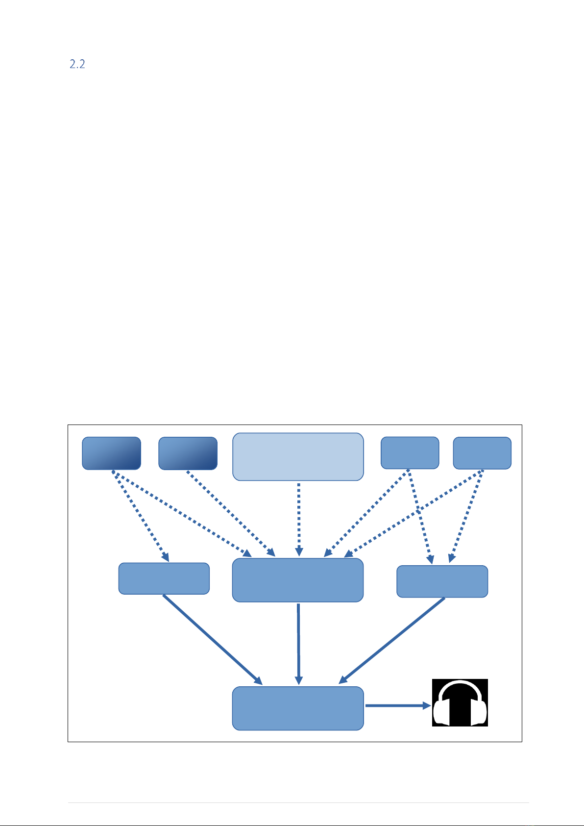
PRIRs
are measurements of binaural
room impulse responses of real
loudspeakers in a real room
Listening Room #3
Presets
contain three Listening Rooms
and run on a DSP
PRIR#3
PRIR#2
Listening Rooms
are constructed from
one or more PRIRs
Listening Room #1
PRIR#4
PRIR#1
Figure 2-1 Operational flow of the Realiser A16
13 | P a g e
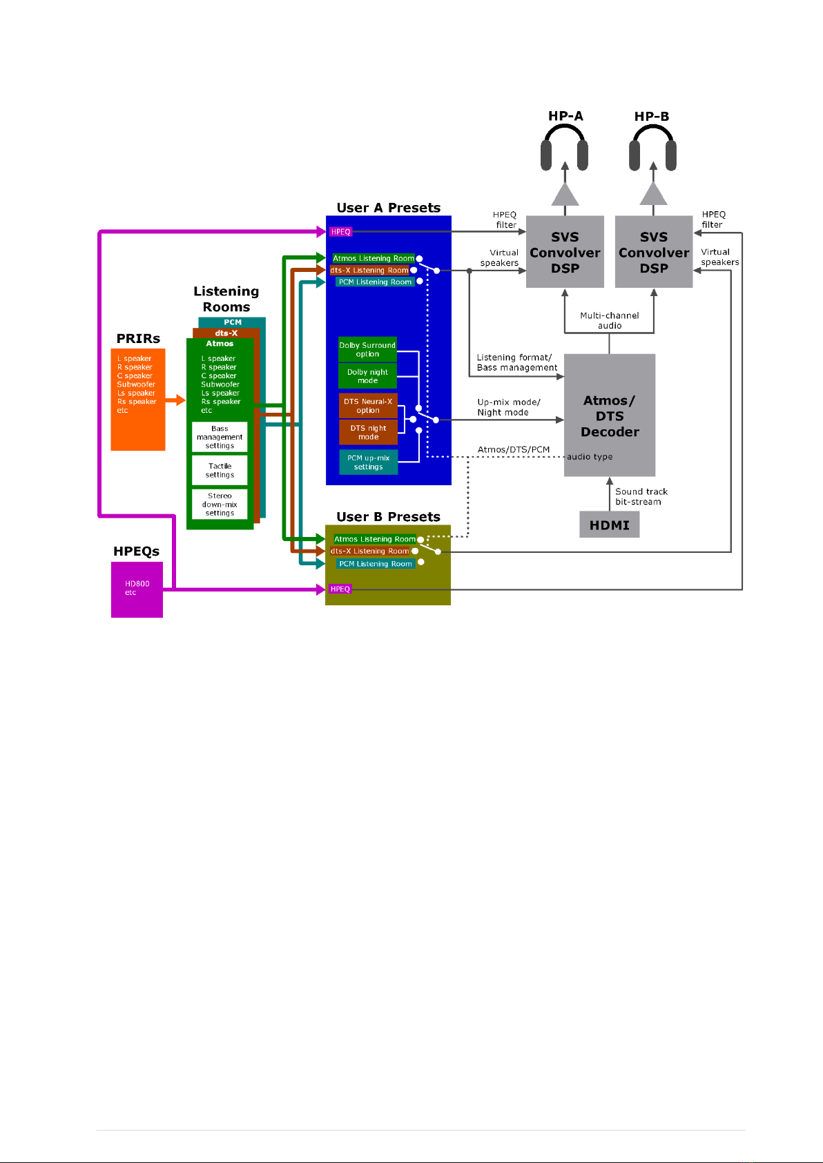
Figure 2-2 Operational overview of the Realiser A16 with audio input from an HDMI source. Audio can also be sourced from
stereo and multichannel analogue inputs, digitally via SPDIF, or from a computer via USB 2.0.

14 | P a g e
Unpacking and parts assembly
2.3.1 Unpacking
The Realiser A16 package contains the items below.
Main processor components:
1. Realiser A16 processor (either the 2U 19” rack-mountable version or the HS version)
2. Power Supply (input 100-240V AC, 50/60 Hz, output 12V DC @ 3A) *
3. IR remote control
Set-top head-tracking components:
4. Set-top IR reference unit (for head-tracking)
5. Set-top cable (3.5mm plug to 3.5mm plug, 4-pole)
6. Set-top extension cable (3.5mm socket to 3.5mm plug, 4-pole)
Head-top head-tracking components:
7. Head-top head-tracker
8. Clip for mounting the head-top to headphones
9. Rubber bands (for connecting head-top clip to headphones - 3 sizes)
10. Head-top cable (2.5mm plug to 2.5mm plug, 4-pole)
11. Head-top extension cable (2.5mm socket to 2.5mm plug, 4-pole)
12. Cable clips (to attach the head-top cable to the headphone cable)
Measurement microphone components:
13. Lanyard (orange neck strap)
14. Clip for lanyard (for supporting in-ear microphones during PRIR measurements)
15. In-ear microphones (one pair)
16. Foam earplugs (for microphones - 3 sizes)
17. Grounding wrist strap (for earthing body during PRIR measurements)
18. Head-band for mounting a Head-top device during PRIR measurements
For the Realiser A16 2U processor there is an optional accessory.
Optional accessories:
19. 2U 19” rack-mount ears
* The power supply is designed for any mains voltage and frequency, and is provided with a mains plug appropriate for the
market to which the Realiser is shipped.
15 | P a g e
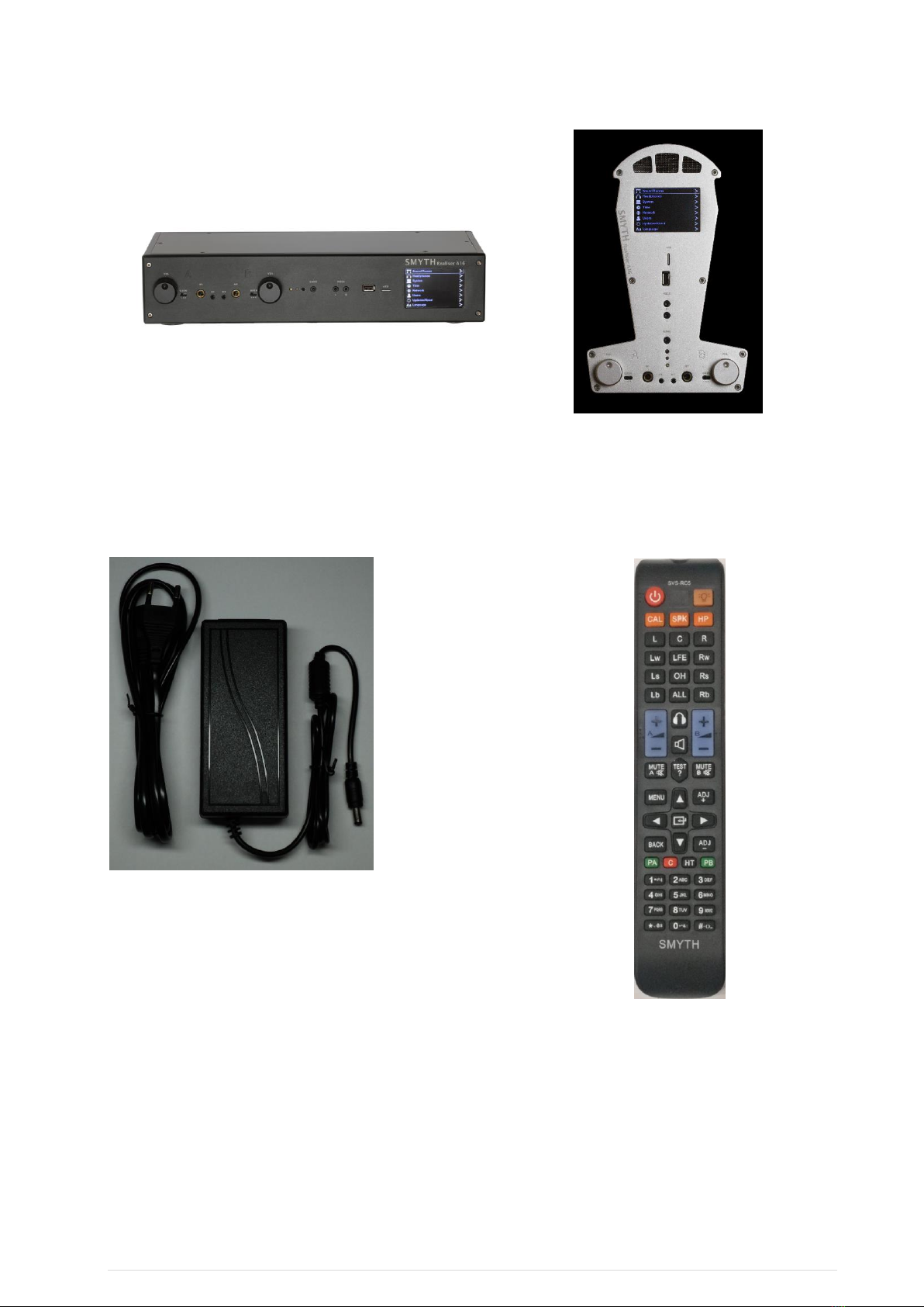
2.3.1.1 Unpacking: Main processor components
Figure 2-3: Realiser A16 processor (either a 2U (left) or HS (right) version)
Figure 2-4 Universal power supply (100-240V,
50/60Hz)
Figure 2-5 Remote
control (IR)

16 | P a g e
2.3.1.2 Unpacking: Set-top head-tracking components
Figure 2-6: Set-top IR reference for head-tracking
Figure 2-7: Set-top cable (3.5mm plug to 3.5mm plug, 4-pole)
Figure 2-8: Set-top extension cable (3.5mm socket to 3.5mm plug, 4-pole)

17 | P a g e
2.3.1.3 Unpacking: In-ear measurement microphone components
Figure 2-9: Lanyard (for supporting microphones during measurements)
Figure 2-10: Microphone cable support clip (connects to the lanyard and
provides strain relief to the microphones when inserted in the ear canals)
Figure 2-11: In-ear measurement microphones (one pair)

18 | P a g e
Unpacking: In-ear measurement microphone components (cont.)
Figure 2-12: Ear foam (seals the microphones when inserted
in the ear canal –4 pairs in 3 sizes)
Figure 2-13: Grounding wrist-strap (used during microphone measurements
to reduce body-induced hum)
Figure 2-14: Head-band
19 | P a g e
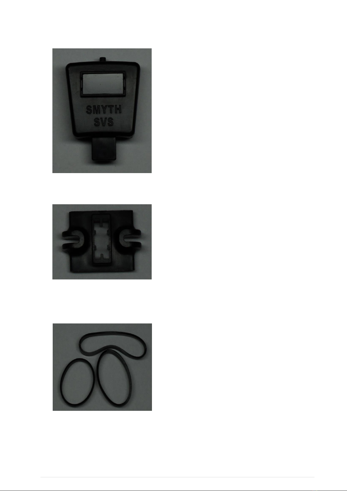
2.3.1.4 Unpacking: Head-top head-tracking components
Figure 2-15:Head-top head-tracking device
Figure 2-16:Clip for mounting the head-top device
(connects to the headphone head-band)
Figure 2-17:Rubber bands (3 sizes)
(connects the clip to a headphone head-band)
Other manuals for Realiser A16
1
Table of contents


