Snell IQOTR31 Operator's manual

snellgroup.com
User Instruction Manual
IQOTR31
3G/HD/SD-SDI Single Mode Fiber Optic Transceiver

IQOTR31 www.snellgroup.com Information and Notices
Issue 1 Rev 1 Page 2 ©2012 Snell Limited
Information and Notices
Copyright and Disclaimer
Copyright protection claimed includes all forms and matters of copyrightable material and
information now allowed by statutory or judicial law or hereinafter granted, including without
limitation, material generated from the software programs which are displayed on the screen
such as icons, screen display looks etc.
Information in this manual and software are subject to change without notice and does not
represent a commitment on the part of Snell Limited. The software described in this manual is
furnished under a license agreement and can not be reproduced or copied in any manner
without prior agreement with Snell Limited. or their authorized agents.
Reproduction or disassembly of embedded computer programs or algorithms prohibited.
No part of this publication can be transmitted or reproduced in any form or by any means,
electronic or mechanical, including photocopy, recording or any information storage and
retrieval system, without permission being granted, in writing, by the publishers or their
authorized agents.
Snell operates a policy of continuous improvement and development. Snell reserves the right
to make changes and improvements to any of the products described in this document
without prior notice.
Contact Details
Customer Support
For further details of our Regional Customer Support Offices, please visit the Snell website
and navigate to Support/Customer Support Contacts.
http://www.snellgroup.com/support/customer-support/customer-support/
Customers with a support contract should call their personalized number, which can be found
in their contract, and be ready to provide their contract number and details.
United Kingdom (HQ)
+44 (0) 118 921 4214 (tel)
+44 (0) 118 921 4268
Regional Support Contacts
Snell USA
+1 818 556 2616 (tel)
+1 818 556 2626 (fax)
Snell Germany
+49 (0) 6122 98 43 0 (tel)
+49 (0) 6122 98 43 44 (fax)
Snell Spain
+34 91 446 23 07 (tel)
+34 91 446 17 74 (fax)
Snell France
+33 1 41 95 30 50 (tel)
+33 1 41 95 30 51 (fax)
Snell Asia Pacific
+852 2356 1660 (tel)
+852 2575 1690 (fax)
Snell India
+91 124 462 6000 (tel)
+91 124 437 5888 (fax)
Snell Russia
+7 499 248 3443 (tel)
+7 499 248 1104 (fax)
Snell China
+86 10 6515 6158 (tel)
+86 10 6515 5659 (fax)

IQOTR31 www.snellgroup.com Safety Information
Issue 1 Rev 1 Page 3 ©2012 Snell Limited
Safety Information
Warnings
Notes
• All lasers used in this product are Class 1, in
accordance with EN60825-1 as well as 21CFR
1040.10 and 1040.11.
• Laser light can be damaging to the eyes. Optical
fibers and uniters should be handled with great
care.
• The IQOTR31 is designed for use with Class 1 laser systems only. Ensure that all
outputs do not exceed Class 1 as doing so will impair the safety of the system and
may result in damage to the equipment.
• Active fibers should not be handled unless their source can positively be identified
as not exceeding Class 1 limits.
Note: • Optical uniters have shutters to prevent the ingress of dust. These shutters should
only be opened when connecting optical fibers.
• The ends of optical fibers should be cleaned with a liquid fiber cleaner, using a
cotton bud, to ensure that there is no dust present before they are plugged in (the
uniter is polarized).
• Do not disturb or handle the optical fibers.
•1550 nm Tx on the IQOTR31 module
An attenuator is required for short link distances (<15 km) and is fitted by default.
For link distances greater than 15 km, the supplied attenuator may be removed to
increase power. See “Attenuation” on page 13.

IQOTR31 www.snellgroup.com Contents
Issue 1 Rev 1 Page 4 ©2012 Snell Limited
Contents
Information and Notices . . . . . . . . . . . . . . . . . . . . . . . . . . . . . . . . . . . . . . . . . . . . . . . . 2
Safety Information . . . . . . . . . . . . . . . . . . . . . . . . . . . . . . . . . . . . . . . . . . . . . . . . . . . . . 3
1. Introduction. . . . . . . . . . . . . . . . . . . . . . . . . . . . . . . . . . . . . . . . . . . . . . . . . . . . . . . . . 6
1.1 Module Description . . . . . . . . . . . . . . . . . . . . . . . . . . . . . . . . . . . . . . . . . . . . . . . . 6
1.2 Order Codes . . . . . . . . . . . . . . . . . . . . . . . . . . . . . . . . . . . . . . . . . . . . . . . . . . . . . 6
1.3 Rear Panel View . . . . . . . . . . . . . . . . . . . . . . . . . . . . . . . . . . . . . . . . . . . . . . . . . . 6
1.4 Enclosures. . . . . . . . . . . . . . . . . . . . . . . . . . . . . . . . . . . . . . . . . . . . . . . . . . . . . . . 7
1.4.1 B-style Enclosure. . . . . . . . . . . . . . . . . . . . . . . . . . . . . . . . . . . . . . . . . . . 7
1.4.2 A-style Enclosures . . . . . . . . . . . . . . . . . . . . . . . . . . . . . . . . . . . . . . . . . . 7
1.5 Feature Summary . . . . . . . . . . . . . . . . . . . . . . . . . . . . . . . . . . . . . . . . . . . . . . . . . 8
2. Technical Specification . . . . . . . . . . . . . . . . . . . . . . . . . . . . . . . . . . . . . . . . . . . . . . . 9
3. Connections . . . . . . . . . . . . . . . . . . . . . . . . . . . . . . . . . . . . . . . . . . . . . . . . . . . . . . . 11
3.1 Optical Input (RX IN). . . . . . . . . . . . . . . . . . . . . . . . . . . . . . . . . . . . . . . . . . . . . . 11
3.2 Electrical Input (SDI IN). . . . . . . . . . . . . . . . . . . . . . . . . . . . . . . . . . . . . . . . . . . . 11
3.3 Optical Output (TX OUT). . . . . . . . . . . . . . . . . . . . . . . . . . . . . . . . . . . . . . . . . . . 11
3.4 Electrical Outputs (SDI OUT 1). . . . . . . . . . . . . . . . . . . . . . . . . . . . . . . . . . . . . . 11
3.5 Electrical Outputs (RX SDI OUT) . . . . . . . . . . . . . . . . . . . . . . . . . . . . . . . . . . . . 11
4. Card Edge LEDs . . . . . . . . . . . . . . . . . . . . . . . . . . . . . . . . . . . . . . . . . . . . . . . . . . . . 12
5. Attenuation . . . . . . . . . . . . . . . . . . . . . . . . . . . . . . . . . . . . . . . . . . . . . . . . . . . . . . . . 13
6. Controlling the IQOTR31 from the RollCall Control Panel . . . . . . . . . . . . . . . . . . 14
6.1 Information Window. . . . . . . . . . . . . . . . . . . . . . . . . . . . . . . . . . . . . . . . . . . . . . . 14
6.1.1 Unit Status . . . . . . . . . . . . . . . . . . . . . . . . . . . . . . . . . . . . . . . . . . . . . . . 14
6.2 Inputs. . . . . . . . . . . . . . . . . . . . . . . . . . . . . . . . . . . . . . . . . . . . . . . . . . . . . . . . . . 14
6.2.1 Input 1 SDI Rate (SDI IN 1) / Input 2 SDI Rate (RX IN 2) . . . . . . . . . . . 14
6.2.2 Output 1 / Output 2. . . . . . . . . . . . . . . . . . . . . . . . . . . . . . . . . . . . . . . . . 15
6.2.3 Fiber Optic Tx 1 . . . . . . . . . . . . . . . . . . . . . . . . . . . . . . . . . . . . . . . . . . . 15
6.2.4 Fiber Optic Tx 2 . . . . . . . . . . . . . . . . . . . . . . . . . . . . . . . . . . . . . . . . . . . 15
6.3 Memories 1-16 . . . . . . . . . . . . . . . . . . . . . . . . . . . . . . . . . . . . . . . . . . . . . . . . . . 16
6.3.1 Saving a Memory Name. . . . . . . . . . . . . . . . . . . . . . . . . . . . . . . . . . . . . 16
6.3.2 Changing a Memory name. . . . . . . . . . . . . . . . . . . . . . . . . . . . . . . . . . . 16
6.3.3 Recalling a Memory . . . . . . . . . . . . . . . . . . . . . . . . . . . . . . . . . . . . . . . . 16
6.4 Logging . . . . . . . . . . . . . . . . . . . . . . . . . . . . . . . . . . . . . . . . . . . . . . . . . . . . . . . . 17
6.4.1 Fiber Logging. . . . . . . . . . . . . . . . . . . . . . . . . . . . . . . . . . . . . . . . . . . . . 18
6.4.2 Log Field Descriptions . . . . . . . . . . . . . . . . . . . . . . . . . . . . . . . . . . . . . . 19
6.5 RollTrack . . . . . . . . . . . . . . . . . . . . . . . . . . . . . . . . . . . . . . . . . . . . . . . . . . . . . . . 20
6.5.1 Disable All . . . . . . . . . . . . . . . . . . . . . . . . . . . . . . . . . . . . . . . . . . . . . . . 20
6.5.2 Index . . . . . . . . . . . . . . . . . . . . . . . . . . . . . . . . . . . . . . . . . . . . . . . . . . . 20
6.5.3 Source . . . . . . . . . . . . . . . . . . . . . . . . . . . . . . . . . . . . . . . . . . . . . . . . . . 20
6.5.4 Address . . . . . . . . . . . . . . . . . . . . . . . . . . . . . . . . . . . . . . . . . . . . . . . . . 20
6.5.5 Command. . . . . . . . . . . . . . . . . . . . . . . . . . . . . . . . . . . . . . . . . . . . . . . . 21
6.5.6 RollTrack Sending . . . . . . . . . . . . . . . . . . . . . . . . . . . . . . . . . . . . . . . . . 21
6.5.7 RollTrack Status. . . . . . . . . . . . . . . . . . . . . . . . . . . . . . . . . . . . . . . . . . . 21
6.6 Status . . . . . . . . . . . . . . . . . . . . . . . . . . . . . . . . . . . . . . . . . . . . . . . . . . . . . . . . . 22
6.6.1 Factory Defaults. . . . . . . . . . . . . . . . . . . . . . . . . . . . . . . . . . . . . . . . . . . 22
6.6.2 Default Settings . . . . . . . . . . . . . . . . . . . . . . . . . . . . . . . . . . . . . . . . . . . 23
6.6.3 Restart . . . . . . . . . . . . . . . . . . . . . . . . . . . . . . . . . . . . . . . . . . . . . . . . . . 23
6.6.4 Input 1 Name and Input 2 Name . . . . . . . . . . . . . . . . . . . . . . . . . . . . . . 23
7. Controlling the IQOTR31 from an Active Front Panel. . . . . . . . . . . . . . . . . . . . . . 24
7.1 Information Window. . . . . . . . . . . . . . . . . . . . . . . . . . . . . . . . . . . . . . . . . . . . . . . 24

IQOTR31 www.snellgroup.com Contents
Issue 1 Rev 1 Page 5 ©2012 Snell Limited
7.2 Control Window. . . . . . . . . . . . . . . . . . . . . . . . . . . . . . . . . . . . . . . . . . . . . . . . . . 24
IQOTR31 www.snellgroup.com Introduction
Issue 1 Rev 1 Page 6 ©2012 Snell Limited
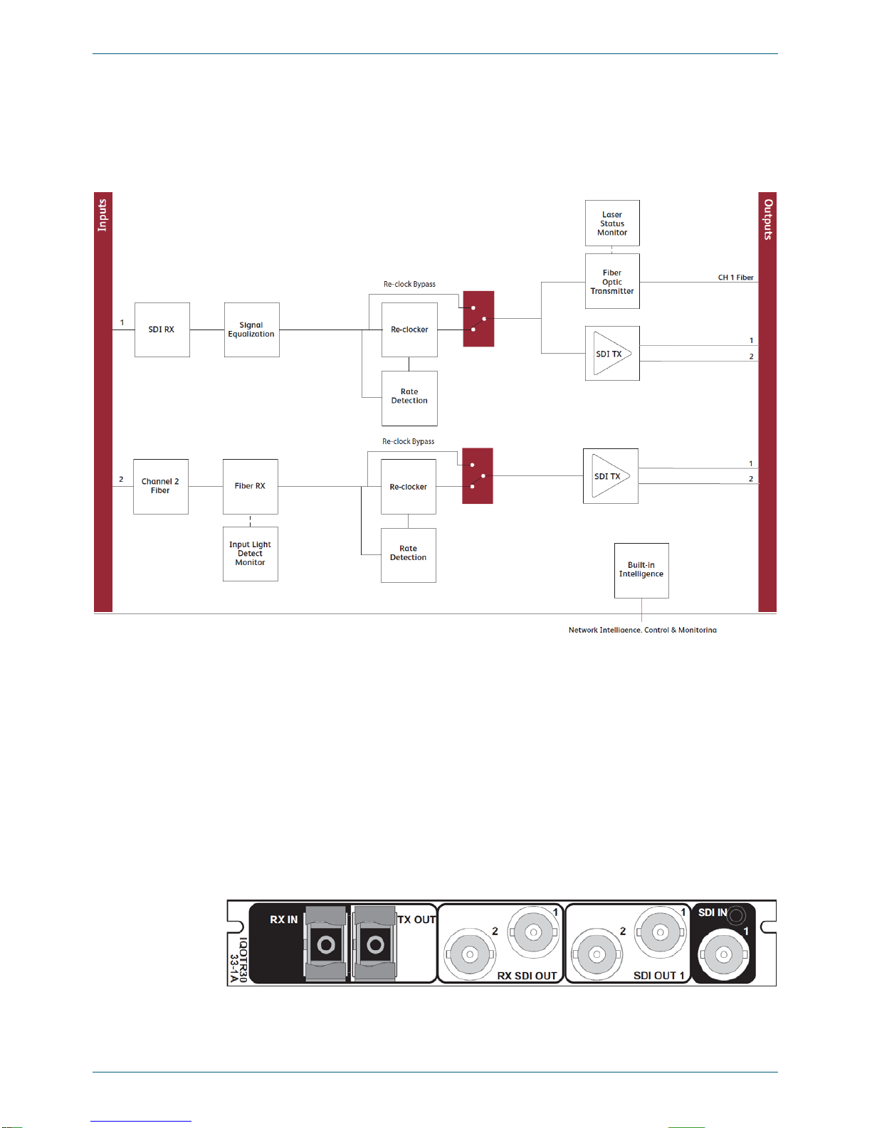
1. Introduction
1.1 Module Description
The IQOTR31 is a fiber optic transceiver for bi-directional conversion of 3 Gbps, HD, and
SD-SDI signals to 1550 nm wavelength optical signals.
1.2 Order Codes
The following product order codes are covered by this manual.
1.3 Rear Panel View
IQOTR3133-1A 1550 nm single mode fiber optic transceiver for HD/SD-SDI. 1 x
HD/SD-SDI input, 2 x HD/SD-SDI outputs, 1 x optical output. 1 x
optical input, 2 x HD SD-SDI outputs
IQOTR3133-1A3 Includes 3G-SDI functionality
IQOTR3133-3G 3G software upgrade for 3G-SDI operation

IQOTR31 www.snellgroup.com Introduction
Issue 1 Rev 1 Page 7 ©2012 Snell Limited
1.4 Enclosures
The module can be fitted into the enclosure types shown.
1.4.1 B-style Enclosure
Enclosure order codes: IQH3B-S-0, IQH3B-S-P
1.4.2 A-style Enclosures
Enclosure order code: IQH1A-S-P
r
Enclosure order codes: IQH3A-S-0, IQH3A-S-P
Enclosure order codes: IQH3A-E-0, IQH3A-E-P, IQH3A-0-0, IQH3A-0-P
Enclosure order code: IQH1A-S-P
Important: An IQH3B enclosure accepts modules with either “A” or “B” order codes. An IQH3A or
IQH1A enclosure accepts modules with “A” order codes only.

IQOTR31 www.snellgroup.com Introduction
Issue 1 Rev 1 Page 8 ©2012 Snell Limited
1.5 Feature Summary
The IQOTR31 provides the following features:
• Reclocking for 3 Gbit/s, 1.5 Gbit/s HD-SDI and 270 Mbit/s SDI signals, or
asynchronous operation for other frequencies (input range 50 Mbit/s to 3 Gbit/s).
• Single mode fiber optic transmitter for 3G HD/SD-SDI and DVB ASI Signals.
• 1550 nm output wavelength.
• Active loop-through 3G/HD/SD-SDI outputs for each input in accordance with
SMPTE424M, SMPTE292M, SMPTE259M and DVB ASI.
• Single mode fiber optic receiver for 3G/HD SD-SDI and DVB ASI Signals.
• Input wavelength range 1260-1620 nm.
• 3G/HD/SD-SDI outputs for CH 2 optical input, in accordance with SMPTE424M,
SMPTE292M, SMPTE259M and DVB ASI.

IQOTR31 www.snellgroup.com Technical Specification
Issue 1 Rev 1 Page 9 ©2012 Snell Limited
2. Technical Specification
Inputs and Outputs
Signal Inputs (Tx)
Electrical 3 GBit/s HD-SDI, 1.485 GBit/s HD-SDI or 270 Mbit/s SD-SDI
(asynchronous operation available at other frequencies)
Connector/Format BNC/75 Ohm panel jack
Conforms to SMPTE 424M (HD level A)
SMPTE 292M (HD)
SMPTE 259M-C (SD)
Inputs 1
Input Cable Length Up to 80 m Belden 1694A @ 3 GBit/s
Up to 180 m Belden 1694A @ 1.5 GBit/s
Up to 350 m Belden 1694A @ 270 Mbit/s
Signal Inputs (Rx)
Optical 3 GBit/s HD-SDI, 1.485 GBit/s HD-SDI or 270 Mbit/s SD-SDI
(asynchronous operation available at other frequencies)
Connector/Format SC/PC singlemode panel uniter
Standard SMPTE 297-2006
Inputs 1
Signal Outputs (Tx)
Electrical 3 GBit/s HD-SDI, 1.485 GBit/s HD-SDI or 270 Mbit/s SD-SDI
(asynchronous operation available at other frequencies)
Connector/Format BNC/75 Ohm panel jack
Conforms to SMPTE 424M (HD level A)
SMPTE 292M (HD)
SMPTE 259M-C (SD)
Outputs 2 reclocked active loop-through for CH1 SDI input, 1 reclocked active loop
through for CH2 SDI input
Optical 3 GBit/s HD-SDI, 1.485 GBit/s HD-SDI or 270 Mbit/s SD-SDI
(asynchronous operation available at other frequencies)
Connector/Format SC/PC singlemode panel uniter
Standard SMPTE 297-2006
Outputs 1 per channel
Signal Outputs (Rx)
Electrical 3 GBit/s HD-SDI, 1.485 GBit/s HD-SDI or 270 Mbit/s SD-SDI
(asynchronous operation available at other frequencies)
Connector/Format BNC/75 Ohm panel jack
Conforms to SMPTE 424M (HD level A)
SMPTE 292M (HD)
SMPTE 259M-C (SD)
Outputs 2
Control Interface
GPI/O 2x closing contact via screw terminal (ST) connector
Controls
Functions Available via RollCall Only
Mode Auto/3G/HD/SD
Reclocker On/Off

IQOTR31 www.snellgroup.com Technical Specification
Issue 1 Rev 1 Page 10 ©2012 Snell Limited
Laser Disable On/Off
Rx Input Status Present, Loss/Unknown, Data Rate
Logging Input 1 (2) Type
Input 1 (2) Data Rate
Input 1 (2) Present
Input 1 (2) Error
Input 1 (2) Loss
Tx Laser Bias High Warning, Tx Power Low Warning, Tx Power High
Warning, Tx Laser Wavelength, Rx Power High Warning, Rx Power Low
Warning, Rx Power Measurement
RollTrack Controls On/Off, Index, Source,Address, Command, Status, Sending
RollTrack Outputs Unused
Input 1 (2) Present
Input 1 (2) Rate Unknown
Input 1 (2) Loss
Input 1 (2) 3G
Input 1 (2) HD
Input 1 (2) SD
Tx Laser Bias High Warning, Rx Power High Warning, Rx Power Low
Warning
Indicators
Power OK (Green)
CPU OK (Green Flashing)
Input 1 (2) OK (Green), Bypass (Orange), Loss (Red)
Specifications
Optical Outputs (Tx) 1550 nm Tx
Wavelength 1550 nm
Spectral Width (FWHM) >1 nm (typical)
Output Power 4 dBm (±1 dBm)
Extinction Ratio >7.5:1 (typical)
Transmission Distance Up to 50 km max
Optical Inputs (Rx)
Input Wavelength Range 1260 nm (min.), 1620 nm (max.)
Optical Power Input Range >-3 dBm, <-18 dBm
Detector Damage Threshold -3.5 dBm
Power Consumption
Module Power Consumption 4 W max (A Frames)
3.5 W max (B Frames)

IQOTR31 www.snellgroup.com Connections
Issue 1 Rev 1 Page 11 ©2012 Snell Limited
3. Connections
This section describes the physical input and output connections provided by the IQOTR31.
3.1 Optical Input (RX IN)
Optical input (Rx IN) to the module is via a single SC/PC singlemode panel uniter.
3.2 Electrical Input (SDI IN)
Electrical input (SDI IN) to the module is via a single BNC 75 ohm panel jack connector.
3.3 Optical Output (TX OUT)
There is a single optical output from the unit via an SC/PC singlemode panel uniter. The input
source for this output is the SDI IN connector.
3.4 Electrical Outputs (SDI OUT 1)
There are two serial digital outputs via BNC 75 ohm panel jack connectors. The input source
for these outputs is the SDI IN connecor.
3.5 Electrical Outputs (RX SDI OUT)
There are two serial digital outputs via BNC 75 ohm panel jack connectors. The input source
for these outputs is the RX IN connector.

IQOTR31 www.snellgroup.com Card Edge LEDs
Issue 1 Rev 1 Page 12 ©2012 Snell Limited
4. Card Edge LEDs
The LEDs on the edge of the module indicate its operating status:
LED Color Description
POWER OK Green Indicates that a positive power supply is present.
CPU OK Green This LED will flash to indicate that the CPU is running.
ERROR Red This LED indicates board fault conditions.
When the unit is booting, this LED is illuminated, until the
SDI is enabled.
WARNING Yellow This LED is illuminated if one or more of the SDI inputs is
not valid or if the reference signal is missing when the unit is
set to Lock to Reference.
OK Green Indicates that the module is operating correctly.

IQOTR31 www.snellgroup.com Attenuation
Issue 1 Rev 1 Page 13 ©2012 Snell Limited
5. Attenuation
The IQOTR31 has 1550 nm transmission lasers. The lasers have a higher optical power
output than the 1310 nm variety. For link distances less than 15 km, this power is suffiecient to
saturate receivers.As a precaution, all units with 1550 nm transmission lasers are fitted with a
5 dBm attenuator. For distances greater than 15 km, it may be desirable to use the extra
optical power, in which case the attenuator can be removed.
To remove the attenuator:
1. Remove the card from the IQ enclosure.
2. Press down on the blue latch that holds the optical fiber connector in place and
withdraw the opitcal fiber.
3. Press down on the blue latch that holds the attenuator in place and remove withdraw
the attenuator from the SFP module.
4. Push the optical fiber connector directly into the SFP module. It will click when it is in
place.
5. Refit the card into the IQ enclosure.
Note: Take care not to touch the exposed glass tip of the optical fiber. If this does happen, clean
the exposed tip with an isopropyl alcohol wipe.
Optical Fiber Cables Attenuator SFP Module
IQOTR31 www.snellgroup.com Controlling the IQOTR31 from the RollCall Control Panel
Issue 1 Rev 1 Page 14 ©2012 Snell Limited
6. Controlling the IQOTR31 from the RollCall Control Panel
6.1 Information Window
The information window is displayed in the upper-right corner of each screen and displays
basic information about the input status, video, audio and reference status of the module.
6.1.1 Unit Status
The first two lines of the Unit Status display the input status, detected rate, and input selection
method for Input 1.
The third and fourth lines of the Unit Status display the same information for Input 2.
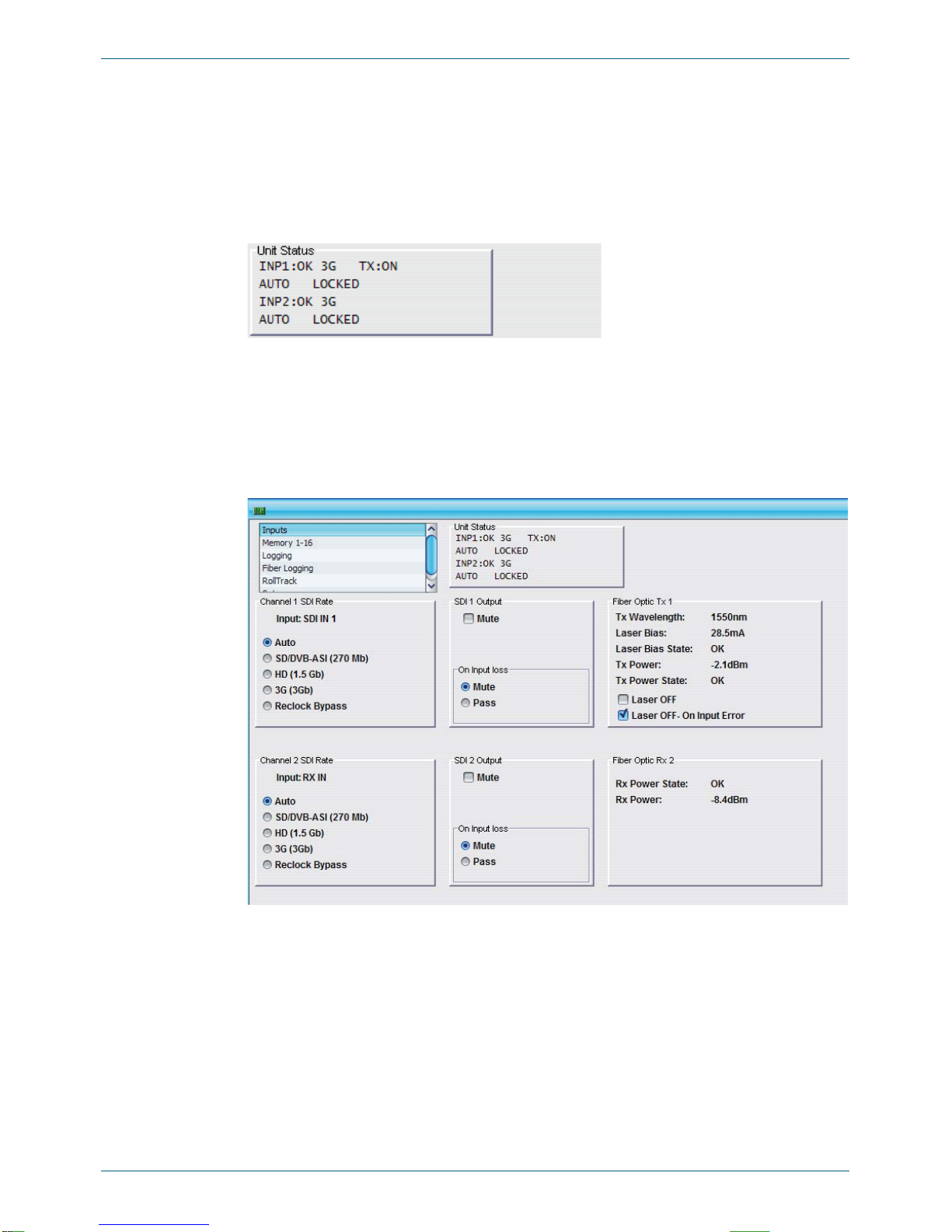
6.2 Inputs
The Inputs screen enables the type of input signal to be selected.
6.2.1 Input 1 SDI Rate (SDI IN 1) / Input 2 SDI Rate (RX IN 2)
•Auto: When selected, the unit will automatically detect and reclock any valid input
signal, and the detected rate will be displayed in the Unit Status.
If anything else is detected, the output will not be reclocked. If the On Input Loss /
Mute option is selected, the output will be muted; or, if the On Input Loss / Pass
option is selected, the output will be passed through.
•SD/DVB-ASI (270 Mb): When selected, the unit will reclock only SD/DVB-ASI (270
Mb) signals.
When selected, the On Input Loss controls are greyed out and are inactive. If any
other standard is applied to the unit, the output will be muted.

IQOTR31 www.snellgroup.com Controlling the IQOTR31 from the RollCall Control Panel
Issue 1 Rev 1 Page 15 ©2012 Snell Limited
•HD (1.5 Gb): When selected, the unit will reclock only HD (1.5 Gb) signals.
When selected, the On Input Loss controls are greyed out and are inactive. If any
other standard is applied to the unit, the output will be muted.
•3G (3 Gb): When selected, the unit will reclock only 3G (3 Gb) signals.
When selected, the On Input Loss controls are greyed out and are inactive. If any
other standard is applied to the unit, the output will be muted.
•Reclock Bypass: When selected, the unit will not reclock the input signal. If a
supported rate is detected, the Unit Status will display the detected rate, otherwise, ***
will be displayed.
• If the On Input Loss / Mute option is selected, the output will be muted whenever a
recoginized rate is not detected; or, if the On Input Loss / Pass option is selected,
any signal standard, frequency, etc… will pass through.
6.2.2 Output 1 / Output 2
•Mute: When selected, this option applies a mute on the output.
•On Input loss / Mute: When selected, if the Input signal is lost, the output signal will
be muted.
•On Input loss / Pass: When selected, if the input signal is lost, it will be passed
unchanged.
6.2.3 Fiber Optic Tx 1
This section displays the following information about the fiber optic output signal:
• Tx Wavelength
• Laser Bias
• Laser Bias State
• Tx Power
• Tx Power State
•Laser OFF: Selecting this option disables the laser.
•Laser OFF - On Input Loss: Selecting this option disables the laser if the input signal
is lost.
6.2.4 Fiber Optic Tx 2
This section displays the following information about the fiber optic input signal:
• Rx Power
• Rx Power State
Note: These controls only apply to the SDI outputs on the BNC. The laser output is controlled by
the Laser OFF and Laser OFF - On Input Loss controls.
Note: These controls only apply to the fiber optic output signal. The SDI outputs on the BNC are
controlled by the Mute and On Input Loss - Mute controls.
When the unit is forced to a particular standard, the laser controls are not grayed out, and
the laser will still be active if an incorrect standard is applied unless Laser OFF - On Input
Loss is selected.

IQOTR31 www.snellgroup.com Controlling the IQOTR31 from the RollCall Control Panel
Issue 1 Rev 1 Page 16 ©2012 Snell Limited
6.3 Memories 1-16
The Memories screen enables up to 16 setups to be saved and recalled later. The default
memory names can be changed to provide more meaningful descriptions.
6.3.1 Saving a Memory Name
To save settings:
• In the Save Memory column, select a memory location, and then click Save. The
current settings are saved and the memory appears in the Recall Memory column.
6.3.2 Changing a Memory name
• In the Save Memory Name field, type the new memory name, and then click S. To
return the memory to its default value, click the preset button (P).
Use the Recall Memory function to recall the settings saved in a memory location.
Last Recalled Memory displays the most recently recalled memory. An asterisk next
to the name displayed in the Last Recalled Memory field indicates that one or more
controls has been changed since the memory was recalled.
6.3.3 Recalling a Memory
• In the Recall Memory column, select the memory to recall. The recalled settings will
be applied and the memory name will appear in the Last Recalled Memory section.

IQOTR31 www.snellgroup.com Controlling the IQOTR31 from the RollCall Control Panel
Issue 1 Rev 1 Page 17 ©2012 Snell Limited
6.4 Logging
Information about several parameters can be made available to a logging device that is
connected to the RollCall network.

IQOTR31 www.snellgroup.com Controlling the IQOTR31 from the RollCall Control Panel
Issue 1 Rev 1 Page 18 ©2012 Snell Limited
6.4.1 Fiber Logging
The Fiber Logging screen displays the current log information for the Fiber Optic module.
Each logging screen comprises three columns:
•Log Enable: Select the check boxes that correspond to the parameters for which log
information should be collected.
•Log Field: Displays the name of the logging field.
•Log Value: Displays the current log value.

IQOTR31 www.snellgroup.com Controlling the IQOTR31 from the RollCall Control Panel
Issue 1 Rev 1 Page 19 ©2012 Snell Limited
6.4.2 Log Field Descriptions
Log Field Description
SN= Displays the module serial number.
OS_VERSION= Displays the operating system name and version.
BUILD_NUMBER= Displays the build number.
HARDWARE_VERSION= Displays the hardware version number.
UPTIME= Displays the time since the last restart in the format
ddd:hh:mm:ss.
LICENSED_OPTIONS= Displays any specially licensed options, if applicable.
INPUT_N_IDENT= Display the input ID.
INPUT_N_NAME= Displays the input name.
INPUT_N_TYPE= This displays the type of input as specified by the unit’s
configuration. Valid values are 3G / HD /SD SDI.
INPUT_N_STATE= Displays the current input state. Valid values are:
•OK
• WARN:Mismatch
• FAIL:Lost
Note: WARN:Mismatch indicates that the input and output
standards are not the same.
INPUT_N_SDIRATE= Displays the input bitrate.
OUTPUT_1_LASER_BIAS_STATE= Displays the current output 1 laser bias state. Valid values are:
•OK
• WARN:Mismatch
• FAIL:Lost
OUTPUT_1_LASER_BIAS= Displays the bias level, in mA.
OUTPUT_1_TX_POWER_STATE= Displays the current Tx power state. Valid values are:
•OK
• WARN:Mismatch
• FAIL:Lost
OUTPUT_1_TX_POWER= Displays the Tx power in dBm.
OUTPUT_WAVELNGTH= Displays the wavelength in nm.
INPUT_N_RX_POWER_STATE= Displays the power status. Valid values are:
•OK
• WARN
• FAIL
INPUT_N_RX_POWER= Displays the Rx power in dBm.

IQOTR31 www.snellgroup.com Controlling the IQOTR31 from the RollCall Control Panel
Issue 1 Rev 1 Page 20 ©2012 Snell Limited
6.5 RollTrack
The RollTrack screen allows information to be sent, via the RollCall™ network, to other
compatible units connected on the same network.
Use the settings on the RollTrack screen to:
• Enable or disable the RollTrack functions.
• Configure up to 16 RollTrack outputs.
• Specify the conditions that trigger RollTrack data transmission.
• Set RollTrack destinations.
• Specify the RollTrack commands to be sent.
6.5.1 Disable All
When checked, all RollTrack items are disabled.
6.5.2 Index
This slider enables up to 70 RollTrack outputs to be setup. Dragging the slider selects the
RollTrack Index number, displayed below the slider. Clicking the Pbutton selects the default
value.
6.5.3 Source
This slider enables the source of information that triggers the transmission of data to be
selected. Dragging the slider selects the RollTrack source, displayed below the slider. Clicking
the Pbutton selects the preset value. When no source is selected, Unused is displayed.
6.5.4 Address
This item enables the address of the selected destination unit to be set.
The address may be changed by typing the new destination in the text area and then selecting
the Sbutton to save the selection. Clicking the Pbutton returns to the default preset
destination.
The RollTrack address consists of four sets of numbers, for example, 0000:10:01*99.
• The first set (0000) is the network segment code number.
Table of contents
Other Snell Transceiver manuals


