Snell IQOTR40 User manual

User Manual
IQOTR40, IQOTR41, IQOTR42,
IQOTR43, IQOTR44, IQOTR45
IQOTR99
3G/HD/SD-SDI Multi-Channel Fiber
Transceiver
snellgroup.com

IQOTR40/41/42/43/44/45/99 www.snellgroup.com
Contents
Module Description........................................................................................................................... 3
Block Diagram................................................................................................................................... 3
Rear Panel View............................................................................................................................... 3
Order Codes ..................................................................................................................................... 4
Feature Summary............................................................................................................................. 5
Technical Profile ............................................................................................................................... 6
Inputs and Outputs........................................................................................................................ 6
Controls......................................................................................................................................... 6
Specifications................................................................................................................................ 7
Connections...................................................................................................................................... 9
SDI Inputs...................................................................................................................................... 9
Fiber Inputs ................................................................................................................................... 9
SDI Outputs................................................................................................................................. 10
Fiber Outputs............................................................................................................................... 10
Card Edge Controls ........................................................................................................................ 11
Controlling the IQOTRXX from the RollCall Control Panel............................................................. 12
Unit Status................................................................................................................................... 12
System-Setup Screen ................................................................................................................. 13
SDI-Inputs 1-4 Screen................................................................................................................. 14
Fiber-Inputs 1-4 Screen............................................................................................................... 16
Output-Fiber Screen.................................................................................................................... 18
System-Memory 1-16 Screen...................................................................................................... 19
Logging........................................................................................................................................ 20
RollCall Log Fields................................................................................................................... 25
System-RollTrack Screen............................................................................................................ 27
This information applies to the transceiver modules in the Optical Converter Platform range. In the
case of the IQOTR99, some of the RollCall screens will be missing if the SFPs for the channels
associated with those screens are not fitted and, in some cases, although the screen will be
present, the group boxes or controls associated with particular channels will be missing or
disabled.
The different versions of the standard product simply have different wavelength fiber transmitters
fitted.
Issue 1 Rev 2 © 2012 Snell Limited
Page 2
IQOTR40/41/42/43/44/45/99 www.snellgroup.com
Module Description
The IQOTR40-45 range converts four single mode fiber optic signals to four 3G/HD/SD-SDI
outputs and four 3G/HD/SD-SDI signals to four single mode fiber optic outputs. The unit is
available in single or dual width versions with either DIN1.0/2.3, HDBNC or BNC connectors.
The IQOTR99 is a special version of the product with a partial fit of channels and/or with non-
standard combinations of transmitter wavelengths.
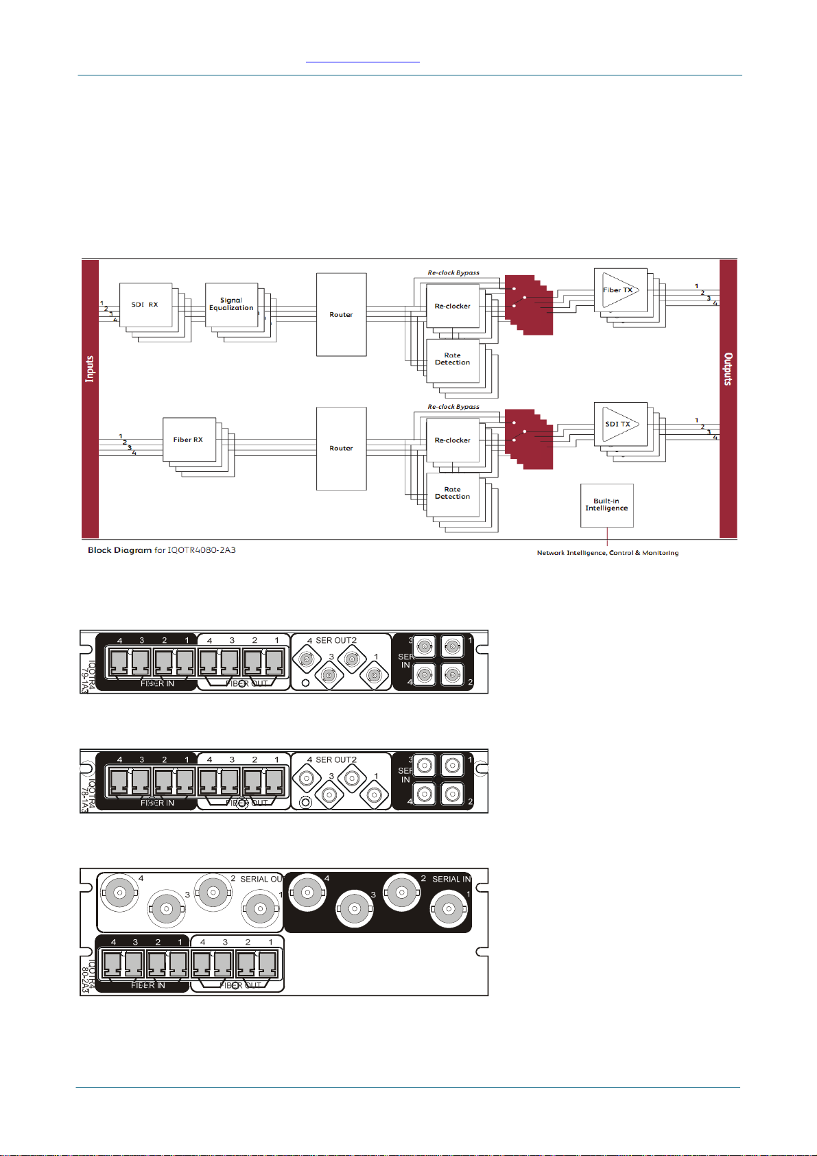
Block Diagram
Rear Panel View
Single width Fibre and DIN1.0/2.3 (IQOTR4_78-1A3)
Single width Fibre and HD BNC (IQOTR4_79-1A3)
Double width Fibre and BNC (IQOTR4_80-2A3)
Issue 1 Rev 2 © 2012 Snell Limited
Page 3

IQOTR40/41/42/43/44/45/99 www.snellgroup.com
Order Codes
Versions of the module cards available are:
SFP fit options for different wavelength operation.
CH1/2 CH3/4
IQOTR40 Dual 1310nm Dual 1310nm
IQOTR41 Dual 1550nm Dual 1550nm
IQOTR42 1270/1290nm 1310/1330nm
IQOTR43 1350/1370nm 1390/1410nm
IQOTR44 1470/1490nm 1510/1530nm
IQOTR45 1550/1570nm 1590/1610nm
IQOTR4078-1A3 3G/HD/SD-SDI multi-channel fiber transceiver. 4 x 3G/HD/SD-SDI inputs
(DIN 1.0/2.3), 4 x 1310nm optical outputs.
IQOTR4079-1A3 3G/HD/SD-SDI multi-channel fiber transceiver. 4 x 3G/HD/SD-SDI inputs
(HD-BNC), 4 x 1310nm optical outputs.
IQOTR4080-2A3 3G/HD/SD-SDI multi-channel fiber transceiver. 4 x 3G/HD/SD-SDI inputs
(BNC), 4 x 1310nm optical outputs.
IQOTR4178-1A3 As IQOTR4078-1A3 but fitted with 1550nm optical transmitters
IQOTR4179-1A3 As IQOTR4079-1A3 but fitted with 1550nm optical transmitters
IQOTR4180-2A3 As IQOTR4080-2A3 but fitted with 1550nm optical transmitters
IQOTR4278-1A3 As IQOTR4078-1A3 but fitted with 1270-1330nm CWDM optical transmitters
IQOTR4279-1A3 As IQOTR4079-1A3 but fitted with 1270-1330nm CWDM optical transmitters
IQOTR4280-2A3 As IQOTR4080-2A3 but fitted with 1270-1330nm CWDM optical transmitters
IQOTR4378-1A3 As IQOTR4078-1A3 but fitted with 1350-1410nm CWDM optical transmitters
IQOTR4379-1A3 As IQOTR4079-1A3 but fitted with 1350-1410nm CWDM optical transmitters
IQOTR4380-2A3 As IQOTR4080-2A3 but fitted with 1350-1410nm CWDM optical transmitters
IQOTR4478-1A3 As IQOTR4078-1A3 but fitted with 1470-1530nm CWDM optical transmitters
IQOTR4479-1A3 As IQOTR4079-1A3 but fitted with 1470-1530nm CWDM optical transmitters
IQOTR4480-2A3 As IQOTR4080-2A3 but fitted with 1470-1530nm CWDM optical transmitters
IQOTR4578-1A3 As IQOTR4078-1A3 but fitted with 1550-1610nm CWDM optical transmitters
IQOTR4579-1A3 As IQOTR4079-1A3 but fitted with 1550-1610nm CWDM optical transmitters
IQOTR4580-2A3 As IQOTR4080-2A3 but fitted with 1550-1610nm CWDM optical transmitters
Note: All these versions are also available for the new IQ 3U B enclosure. Please append order
code with A3 (A enclosure) or B3 (B enclosure) as appropriate.
Issue 1 Rev 2 © 2012 Snell Limited
Page 4

IQOTR40/41/42/43/44/45/99 www.snellgroup.com
Feature Summary
•4 channels of fiber outputs single mode fiber optic transmitter for 3G/HD/SDSDI
and DVB ASI signals.
•4 channels of electrical SDI inputs for 3G/HD/SDSDI and DVB ASI signals.
•4 channels single mode fiber optic receiver for 3G/HD/SDSDI and DVB ASI
signals.
•4 channels of electrical SDI outputs for 3G/HD/SDSDI and DVB ASI signals.
•Output wavelengths of 1310 nm, 1550 nm or CWDM combinations.
•Input wavelengths of 1260 nm to 1610 nm.
•Reclocking for 3 Gbps, 1.5 Gbps HD-SDI and 270 Mbps SDI signals, or
asynchronous operation for other frequencies.
•Input channel routing – electrical SDI inputs 1 to 4 can be routed to fiber output
channels 1 to 4, and fiber inputs 1 to 4 can be routed to electrical SDI output
channels 1 to 4.
•Input selection logic – two configurations can be preset with routing.
Configurations can be selected on input signal status.
•RollCall monitoring allows all signal paths to be managed
•High density DIN1.0/2.3 and HDBNC options provide compact space saving
single slot solution.
•The SFP receivers and transmitters are hot-pluggable – i.e. they may be
removed and inserted without removing power from the module.
Issue 1 Rev 2 © 2012 Snell Limited
Page 5

IQOTR40/41/42/43/44/45/99 www.snellgroup.com
Technical Profile
Inputs and Outputs
Signal Inputs (Tx)
Electrical 3 Gbps HD-SDI, 1.485 Gbps HD-SDI or 270 Mbps SD-SDI (asynchronous
operation available at other frequencies)
Connector / format BNC / 75 Ohm, DIN1.0/2.3, HDBNC panel jack
Conforms to SMPTE 424M (HD level A)
SMPTE 292M (HD)
SMPTE 259M-C (SD)
Inputs 4
Input cable length Up to 100m Belden 1694A @ 3Gbps
Up to 150m Belden 1694A @ 1.5 Gbps
Up to 250m Belden 1694A @ 270 Mbps
Signal Inputs (Rx)
Optical 3 Gbps HD-SDI, 1.485 Gbps HD-SDI or 270 Mbps SD-SDI (asynchronous
operation available at other frequencies)
Connector / format LC single mode SFP
Conforms to: SMPTE 297-2006
Inputs 4
Signal Outputs (Tx)
Optical 3 Gbps HD-SDI, 1.485 Gbps HD-SDI or 270 Mbps SD-SDI (asynchronous
operation available at other frequencies)
Connector / format LC single mode SFP
Conforms to SMPTE 297-2006
Outputs 1 to 4 per Channel
Signal Outputs (Rx)
Electrical 3 Gbps HD-SDI, 1.485 Gbps HD-SDI or 270 Mbps SD-SDI (asynchronous
operation available at other frequencies)
Connector / format BNC / 75 ohm, DIN1.0/2.3, HDBNC panel jack
Conforms to SMPTE 424M (HD level A)
SMPTE 292M (HD)
SMPTE 259M-C (SD)
Outputs 1 to 4 per Channel
Controls
Indicators
Power OK (Green)
CPU OK (Green flashing)
Good Hardware OK (Green)
Warning SFP fit not as sold (Yellow), SFP warning active (Yellow flashing), OK (Off)
Error Hardware error (Red), SFP alarm active (Red flashing), OK (Off)
Input 1-8 SD-OK (Yellow), HD-OK (Green), 3G-OK (Blue), other-OK (White flashing),
Bypass (Rate colour flashing), Loss (Red)
Issue 1 Rev 2 © 2012 Snell Limited
Page 6

IQOTR40/41/42/43/44/45/99 www.snellgroup.com
RollCall Functions
Input 1-8 rate select 3G, HD, SD, other
Reclock bypass On/Off
Fiber O/P select SDI Input 1-4
Electrical O/P select Fiber Input 5-8
Input status Present, Loss, Unknown, Unrouted, Data Rate
Output Mute On/Off
Laser disable On/Off
Logging Input 1-8 Type
Input 1-8 Bit Rate
Input 1-8 Present
Input 1-8 Loss
Output 1-4 laser bias
Output 1-4 laser power
Output 1-4 laser wavelength
Input 5-8 laser power
Output Configuration
RollTrack controls On/Off, Index, Source, Address, Command, Status, Sending
RollTrack outputs Unused
Input 1-8 Present
Input 1-8 Rate Unknown
Input 1-8 Loss
Input 1-8 3G
Input 1-8 HD
Input 1-8 SD
Output 1-4 laser bias OK
Output 1-4 laser bias High
Output 1-4 laser bias Low
Input 5-8 Power OK
Input 5-8 Power High
Input 5-8 Power Low
Output Configuration
Specifications
Electrical 3 Gbps SDI, SMPTE 424M,
1.5 Gbps HD-SDI, SMPTE 292M
270 Mbps SDI, SMPTE 259MC / DVB-ASI
Connector / format BNC/ 75 Ohm panel jack on standard Snell connector panel
Return loss >-15 dB (270 Mbps, 1.5 Gbps)
>-10 dB (3 Gbps)
Output jitter SD-SDI 0.2 UI (10 Hz) / 0.2 UI (1 kHz)
3G/HD-SDI 1.0 UI (10 Hz) / 0.2UI (100 kHz)
Module power 10.5 W max
Receiver wavelength 1260 – 1610 nm
Optical power 0 dBm to -18 dBm
Input range
Issue 1 Rev 2 © 2012 Snell Limited
Page 7

IQOTR40/41/42/43/44/45/99 www.snellgroup.com
(Depends on SFP fitted)
1310 nm Tx
Wavelength 1310 nm
Spectral width (FWHM) 1.5 nm (typ RMS)
Output power -2 dBm (typ), 0 dBm max
Extinction ratio >7.5:1 (typ)
Transmission distance 10 km max under worst conditions, up to 30 km max
1550 nm Tx
Wavelength 1550 nm
Spectral width (FWHM) 1 nm (max)
Output power 4 dBm max
Extinction ratio >7.5:1 (typ)
Transmission distance Up to 50 Km max
CWDM wavelength Tx
Wavelength 1270 nm – 1410 nm and 1470 nm –1610 nm
Spectral width (FWHM) 1 nm (max)
Output power 2.5 dBm (typ), 5 dBm max
Extinction ratio >9:1 (typ)
Transmission distance Up to 50 km max
Issue 1 Rev 2 © 2012 Snell Limited
Page 8

IQOTR40/41/42/43/44/45/99 www.snellgroup.com
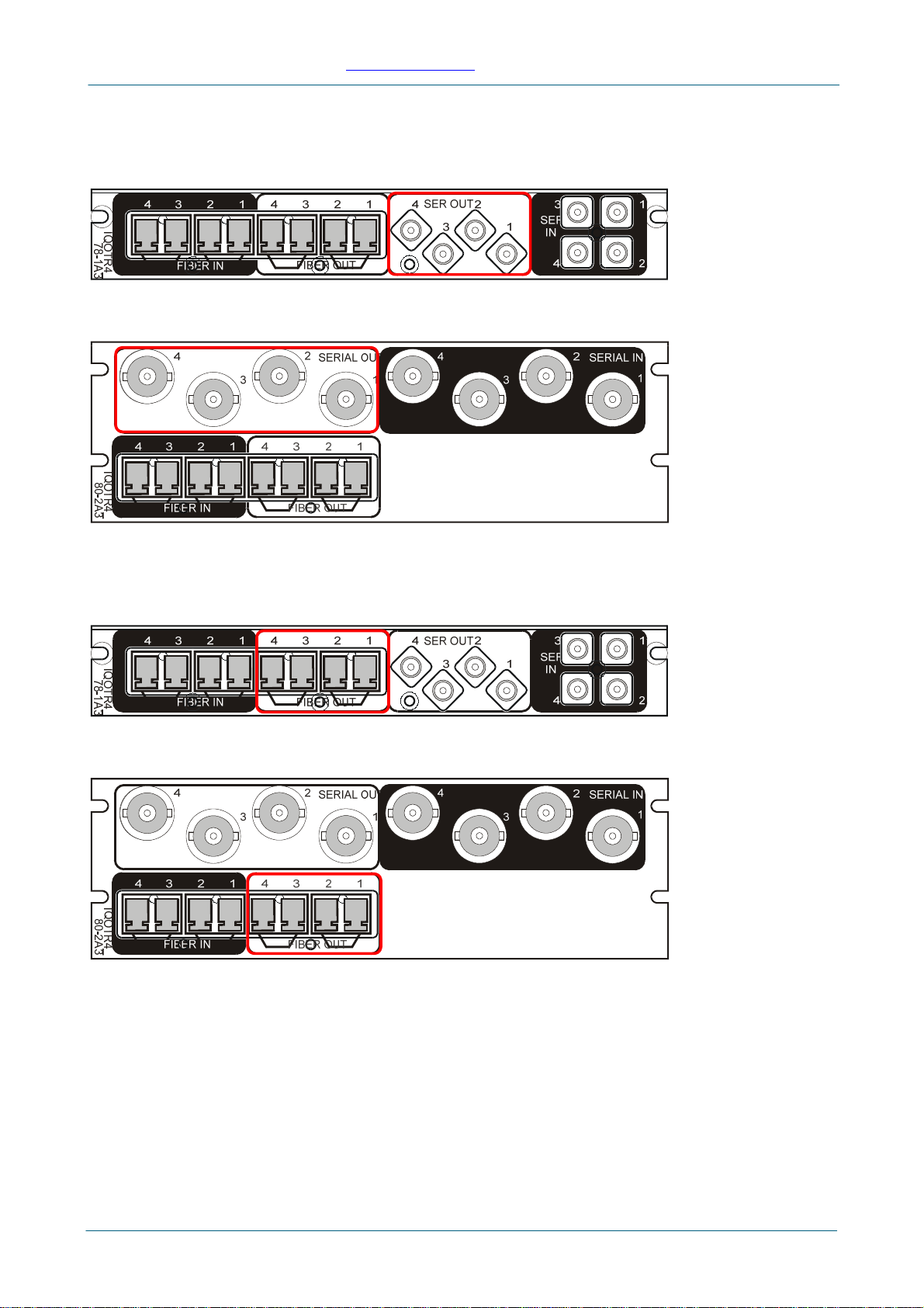
Connections
SDI Inputs IQOTR4_78-1A3 and IQOTX8_79-1A3
SDI inputs to the unit are made via 8 DIN 1.0/2/3 or HD BNC (75ohm) panel jack
connectors.
IQOTR4_80-2A3
SDI inputs to the unit are made via BNC / 75ohm panel jack connectors.
Fiber Inputs IQOTR4_78-1A3 and IQOTX8_79-1A3
Fiber inputs from the unit are made via 4 LC connectors.
IQOTR4_80-2A3
Fiber inputs from the unit are made via 4 LC connectors.
Issue 1 Rev 2 © 2012 Snell Limited
Page 9
IQOTR40/41/42/43/44/45/99 www.snellgroup.com
SDI Outputs
IQOTR4_78-1A3 and IQOTX8_79-1A3
SDI outputs to the unit are made via 8 DIN 1.0/2/3 or HD BNC (75ohm) panel jack
connectors.
IQOTR4_80-2A3
SDI outputs to the unit are made via BNC / 75ohm panel jack connectors.
Fiber Outputs
IQOTR4_78-1A3 and IQOTX8_79-1A3
Fiber outputs from the unit are made via 4 LC connectors.
IQOTR4_80-2A3
Fiber outputs from the unit are made via 4 LC connectors.
Issue 1 Rev 2 © 2012 Snell Limited
Page 10

IQOTR40/41/42/43/44/45/99 www.snellgroup.com
Card Edge Controls
V+ and V- When illuminated these LED’s indicate that the positive and negative supplies
are present.
CPU This led will flash to indicate that the CPU is running.
Input Channel Status (Ch1 to Ch8)
Off Channel is not applicable to this product.
Yellow SD - re-clocker locked at 270 MHz, flashes when in RC-bypass
Green HD - re-clocker locked at 1.485/1.4835 GHz, flashes when in RC-bypass
Blue 3G - re-clocker locked at 2.97/2.967 GHz, flashes when in RC-bypass
White (flashing) Unknown rate detected, forcing RC-bypass. Input might actually be
un-routed with all rates selected in the dialog.
Red No signal present.
Red (flashing) Input detected, but rate is in error. This is as a result of the rate
selection logic on the RollCall dialogue, or the channel is un-routed and not all
rates are selected.
Error (Red) When illuminated indicates that SFPs are fitted incorrectly or missing (see
SFP Fit Errors and Warnings).
When flashing indicates that an SFP status alarm has been activated (e.g.
temperature or supply voltage) other than the Rx Power Alarm.
Warning (Yellow) Illuminates to indicate that the order in which the SFPs are fitted has changed
from the original documented fit (see SFP Fit Errors and Warnings).
Flashes to indicate that an SFP status warning has been activated (e.g.
temperature or supply voltage) other than the Rx Power Warning.
Good (Green) Illuminates to indicate all SFPs are fitted and functioning correctly.
Issue 1 Rev 2 © 2012 Snell Limited
Page 11
IQOTR40/41/42/43/44/45/99 www.snellgroup.com
Issue 1 Rev 2 © 2012 Snell Limited
Page 12
Controlling the IQOTRXX from the RollCall Control Panel
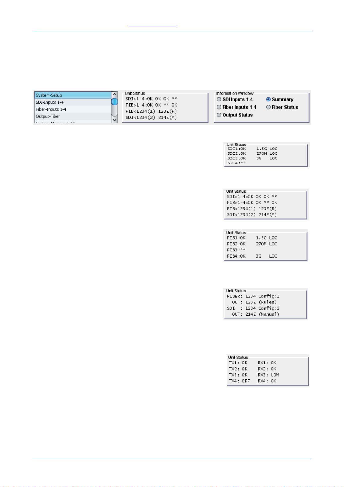
Unit Status
Information about the status of the unit is displayed in the Unit Status section on each RollCall
Control Panel screen. The default is the Summary.
The radio buttons in the Information Window are used to select what is displayed in Unit Status.
•Summary – shows a cryptic view of the channel input
status, the output routing and the mode selection. On the
top two lines it shows signals present on SDI inputs 1, 2
and 3 and on Fiber inputs 1, 2 and 4. On the bottom two
lines it shows the selected Config with Routing and Mode
for the SDI →Fiber and Fiber →SDI channels. Blank status means the fiber receiver isn’t
fitted for that channel or a transmitter is fitted by mistake.
•SDI Inputs 1-4 – shows a more detailed view of SDI
channel input status; includes status field, bit rate and
whether locked or bypassing the reclocker. Uin the first
field indicates the input is not routed to an output and
therefore its bit rate cannot be measured. Err indicates
that a signal has been detected but its bit rate is not one of
those selected for that input.
•Fiber Inputs 1-4 – as SDI Inputs 1-4 but for the fiber
channels.
•Output Status – shows the status for the Fiber and SDI
outputs. On the top two lines it shows that SDI I/Ps 1, 2 and 3 are routed to Fiber O/Ps 1, 2
and 3, Fiber O/P 4 shows Ewhich means it is muted (laser off) due to an input error, Config
1is selected and the Mode is Rules. The bottom two lines
show that Fiber I/Ps 2, 1 and 4 are routed to SDI O/Ps 1,
2 and 3, SDI O/P 4 shows E, muted due to input error,
Config 2is selected and the mode is Manual. Minstead
of Ein the routing status indicates muted using the
channel’s Mute or Laser Off control. An X means a Fiber
Transmitter is missing or a Fiber Receiver is fitted by mistake. A ‘space’ in this position
means that the product does not require a Fiber Transmitter to be fitted for that channel
(applies to IQOTR99).
•Fiber Status – shows the status of the SFP fiber
transmitters and receivers. LOW or HIGH means low or
high Power; with transmitters this could be an early
indication of a fault, though, with receivers, LOW is the
normal state if there is no input signal. Transmitters have
an additional status to indicate the laser is turned OFF.
NONE indicates that a Fiber Transmitter is missing or a Receiver fitted by mistake. ‘Bla
status indicates that the product does require a Fiber Transmitter to be fitted for that
channel (applies to IQOTR99) or a Fiber Receiver is missing or a Tr
nk’
ansmitter is fitted by
mistake.
IQOTR40/41/42/43/44/45/99 www.snellgroup.com
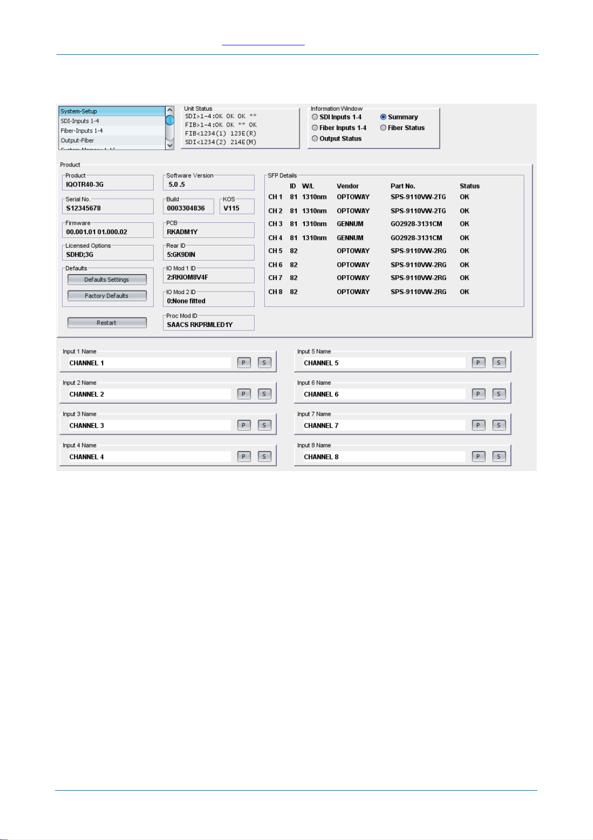
System-Setup Screen
The Setup screen displays basic information about the unit. Use the functions on the screen to
restart the unit, return all settings to their factory defaults, and to change the names of the inputs.
Product: The top left part of the screen shows the various versions, options, identifiers, etc.,
associated with the product’s hardware, firmware and software and also provides a means of
setting controls to defaults or restarting the unit. Note that the Firmware release is in two parts,
the left-hand being for the Administration module FPGA and the right-hand part being for the I/O
module FPGA.
To restart the unit, simulating a power-up/power-down cycle, click Restart.
To reset all of the unit’s settings to their factory defaults, click Factory Defaults.
•NOTE: this also clears all of the saved memory settings.
To reset all of the unit’s settings to their factory defaults, leaving user memories intact, click
Default Settings.
SFP Details: The top right part of the screen shows the details of the SFP transmitters and
receivers fitted. The Status column indicates whether the SFPs fitted are correct for the particular
product. The difference between the TR40, 41, 42, 43, 44, 45 products is purely the wavelengths of
the transmitters fitted. NOTE: SFP details are read only at start up so the unit must be restarted if
an SFP is changed.
Input 1-8 Name: The bottom half of the screen has entry fields for 8 Input Names. These are the
input names displayed in logging. To change a name, type the name in the text field and click S.
To return the name to its factory default, click P. Note that Fiber Inputs 1-4 are Inputs 5-8 in this
context.
Issue 1 Rev 2 © 2012 Snell Limited
Page 13
IQOTR40/41/42/43/44/45/99 www.snellgroup.com
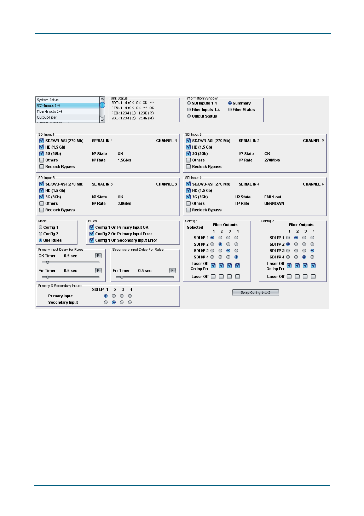
SDI-Inputs 1-4 Screen
The SDI-Inputs screen enables the:
•Inputs and outputs to be configured.
•The configuration mode to be used selected.
•The rules governing configuration use to be specified.
SDI Inputs 1-4
•SD/DVB-ASI (270 Mb):
•HD (1.5Gb):
•3G (3 Gb):
•Others: Check one or more of these checkboxes to determine which types of signal are
deemed to be valid for a particular input. If a signal is present on the input but not selected
as valid, its status will be Error. Others is for signals of type other than the above. Also,
because the reclockers are on the outputs, if an input is detected as present but not routed
to an output, its bit rate will be unknown and its status would be Error unless this box was
checked.
•Reclock Bypass: Check this to bypass the reclocker, which is on the output signal.
•The Channel Ident, I/P Name, I/P State and I/P Rate are shown for each channel.
Config 1 and Config 2
Use the radio buttons to specify the SDI input for each of the four Fiber outputs.
Select Laser Off On Inp Err to apply a mute to the output if there is no valid signal on its input as
defined by the checkboxes; includes signal lost. Select Laser Off to manually apply a mute to the
output.
Issue 1 Rev 2 © 2012 Snell Limited
Page 14

IQOTR40/41/42/43/44/45/99 www.snellgroup.com
Swap Config 1 <> 2
Click Swap Config to swap the Config 1 setup with the Config 2 setup.
Mode
These controls specify which configuration is to be used, or whether the configuration choice
should be made by the rules configured in the Rules section.
Primary & Secondary Inputs
Use the radio buttons to select which input channels are used in the Rules section.
Rules
These controls specify which configuration is to be used if the Use Rules option is selected in the
Mode section. The option enables the configuration to be switched automatically if an input fails
or changes to an inappropriate rate.
•Config 1 On Primary Input OK: this selection will use Config 1 if the Primary Input is
receiving a valid input signal.
•Config 2 On Primary Input Err: this selection will switch to Config 2 if the Primary Input 1
is not receiving a valid input signal.
•Config 1 On Secondary Input Err: this selection will switch to Config 1 if the Secondary
Input is not receiving a valid input signal.
Primary Input Delay for Rules
•OK Timer: this specifies the time that the Primary Input must be receiving a valid signal in
order to be considered ‘OK’ by any rules.
•Err Timer: this specifies the time that Primary Input must be receiving an invalid (or lost)
signal in order to be considered in error by any rules.
Secondary Input Delay for Rules
•Err Timer: this specifies the time that the Secondary Input must be receiving an invalid (or
lost) signal in order to be considered in error by any rules.
NOTE: Because the reclockers that measure the rate of the signals are on the outputs rather than
the inputs of the routing cross-points, an input must be routed in order for its rate to be determined.
Therefore, depending on which Rules are selected, the Primary and/or the Secondary input
channels have to be routed in one or both of the two configurations in order for the rule to work…
•Config 1 On Primary Input OK: Because this is a rule for switching from Config 2 back to
Config 1, the Primary must be routed in Config 2.
•Config 2 On Primary Input Err: Because this is a rule for switching from Config 1 to
Config 2, the Primary must be routed in Config 1.
•Config 1 On Secondary Input Err: Because this is a rule for switching back from Config 2
back to Config 1, the Secondary must be routed in Config 2. Also, to prevent the
configuration switching backwards and forwards between configurations, it must also be
routed in Config 1.
Issue 1 Rev 2 © 2012 Snell Limited
Page 15
IQOTR40/41/42/43/44/45/99 www.snellgroup.com
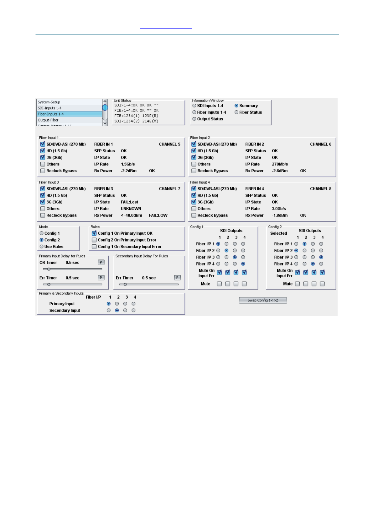
Fiber-Inputs 1-4 Screen
The Fiber-Inputs screen enables the:
•Inputs and outputs to be configured.
•The configuration mode to be used selected.
•The rules governing configuration use to be specified.
Fiber Inputs 1-4
•SD/DVB-ASI (270 Mb):
•HD (1.5Gb):
•3G (3 Gb):
•Others: Check one or more of these checkboxes to determine which types of signal are
deemed to be valid for a particular input. If a signal is present on the input but not selected
as valid, its status will be Error. Others is for signals of type other than the above. Also,
because the reclockers are on the outputs, if an input is detected as present but not routed
to an output, its bit rate will be unknown and its status would be Error unless
•Reclock Bypass: Check this to bypass the reclocker, which is on the output signal.
•The Channel Ident, I/P Name, receiver SFP Status (relating to product SPF fit), I/P State,
I/P Rate, Rx Power (value and alarm status) are shown for each channel.
Issue 1 Rev 2 © 2012 Snell Limited
Page 16

IQOTR40/41/42/43/44/45/99 www.snellgroup.com
Config 1 and Config 2
Use the radio buttons to specify the Fiber input for each of the four SDI outputs.
Select Mute On Inp Err to apply a mute to the output if there is no valid signal on its input as
defined by the checkboxes; includes signal lost. Select Mute to manually apply a mute to the
output.
Swap Config 1 <> 2
Click Swap Config to swap the Config 1 setup with the Config 2 setup.
Mode
These controls specify which configuration is to be used, or whether the configuration choice
should be made by the rules configured in the Rules section.
Primary & Secondary Inputs
Use the radio buttons to select which input channels are used in the Rules section.
Rules
These controls specify which configuration is to be used if the Use Rules option is selected in the
Mode section. The option enables the configuration to be switched automatically if an input fails or
changes to an inappropriate rate.
•Config 1 On Primary Input OK: this selection will use Config 1 if the Primary Input is
receiving a valid input signal.
•Config 2 On Primary Input Err: this selection will switch to Config 2 if the Primary Input 1
is not receiving a valid input signal.
•Config 1 On Secondary Input Err: this selection will switch to Config 1 if the Secondary
Input is not receiving a valid input signal.
Primary Input Delay for Rules
•OK Timer: this specifies the time that the Primary Input must be receiving a valid signal in
order to be considered ‘OK’ by any rules.
•Err Timer: this specifies the time that Primary Input must be receiving an invalid (or lost)
signal in order to be considered in error by any rules.
Secondary Input Delay for Rules
•Err Timer: this specifies the time that the Secondary Input must be receiving an invalid (or
lost) signal in order to be considered in error by any rules.
NOTE: Because the reclockers that measure the rate of the signals are on the outputs rather than
the inputs of the routing cross-points, an input must be routed in order for its rate to be determined.
Therefore, depending on which Rules are selected, the Primary and/or the Secondary input
channels have to be routed in one or both of the two configurations in order for the rule to work…
•Config 1 On Primary Input OK: Because this is a rule for switching from Config 2 back to
Config 1, the Primary must be routed in Config 2.
•Config 2 On Primary Input Err: Because this is a rule for switching from Config 1 to
Config 2, the Primary must be routed in Config 1.
•Config 1 On Secondary Input Err: Because this is a rule for switching back from Config 2
back to Config 1, the Secondary must be routed in Config 2. Also, to prevent the
configuration switching backwards and forwards between configurations, it must also be
routed in Config 1.
Issue 1 Rev 2 © 2012 Snell Limited
Page 17

IQOTR40/41/42/43/44/45/99 www.snellgroup.com
Output-Fiber Screen
The Output-Fiber screen shows status associated with the fiber transmitters.
Fiber Optic Tx 1-4
Shows the fiber transmitter status for each channel. SFP Status relates to the product SPF fit.
Issue 1 Rev 2 © 2012 Snell Limited
Page 18

IQOTR40/41/42/43/44/45/99 www.snellgroup.com
System-Memory 1-16 Screen
Use the Memory function to save up to 16 setups to be recalled later. Default memory names can
be changed to provide more meaningful descriptions.
To save settings:
•In the Save Memory column, select a memory location, and then click Save. The current
settings are saved and the memory appears in the Recall Memory column.
To change a memory name:
•In the Save Memory Name field, type the new memory name, and then click S. To return
the memory to its default value, click the preset button (P).
Use the Recall Memory function to recall the settings saved in a memory location. Last Recalled
Memory displays the most recently recalled memory. If a control is changed after a setup has
been recalled, Last Recalled Memory will display an asterisk (*) beside the memory name.
To recall a memory:
•In the Recall Memory column, select the memory to recall. The recalled set-tings will be
applied and the memory name will appear in the Last Recalled Memory section.
Issue 1 Rev 2 © 2012 Snell Limited
Page 19

IQOTR40/41/42/43/44/45/99 www.snellgroup.com
Logging
Logged parameters are made available to logging devices connected to the RollCall Network.
They are also displayed on a number of RollCall Screens where they can selectively be switched
off to prevent them being logged externally.
Issue 1 Rev 2 © 2012 Snell Limited
Page 20
This manual suits for next models
6
Table of contents
Other Snell Transceiver manuals


