SOGEDIS T0 Series User manual

Série T0
CODES PANNES
et
AUTOTEST

5
3. Operating Instructions
3.1. LCD Screen, Function Buttons & Knobs
3.2. Program List
KNOB
POSITION
PROGRAM
1
Cotton 60°C
2
Cotton 40°C
3
Cotton Prewash
4
Eco 20°C
5
Easy Care
6
Wool
7
Rinse
8
Allergy Safe
9
Spin
10
Delicate / Hand Wash
11
Sports Wear
12
Mix/Duvet*
13
Jeans
14
Daily 60'
15
Rapid 15'**
16
OFF
*Mix algoritm is available for 32, 40, 41+, 42, 44, 44+, 47, 49, 50, 54, 59lts. Duvet algorithm is
available for 55, 60, 61, 62 lts.
**Rapid 15 is available for without twinjet model, Rapid 12 is available for with twinjet model.
PR
Program Selector with ON/OFF
SW1
Start / Pause
SW2
Option Selection
SW3
Spin Speed Selection
SW4
Temperature Selection
LD1
Start / Pause Led
LD2
Option Led
D1
7-segment display 1
D2
7-segment display 2
PR
SW1
SW2
SW3
SW4

6
3.3.
Child Lock
Activation
1. Press the SW2 and SW3 buttons simultaneously for 3 sec.
Deactivation
1. Press the SW2 and SW3 buttons simulaneously for 3 sec.
Child lock during selection:
Machine does not respond to any pressing of buttons or
changing position of program knob. CL at 7 segment display will
make fast blink for 2 sec to
indicate child lock is activated.
Child lock during the program:
Machine does not respond to any pressing of buttons or
changing position of program knob. “CL” is visualized on display for
2 sec to indicate child lock activation with tone D buzzer in models
having buzzer option. After 2 sec “CL” indication if fixed off and
remaining time is visualized on display.
In end condition
When cycle is finished child lock is automatically
deactivated. It is not possible to activate child lock during End mode.
In Error Mode
Child lock will be automatically deactivated when error is
detected
Child lock during delay mode:
Child lock can be activated / deactivated during delay
mode. If child lock is active during delay mode, it will be kept locked
until the end of washing (unless user deactivates by pressing SW2
and SW3 buttons simultaneously for 3 sec.)
7
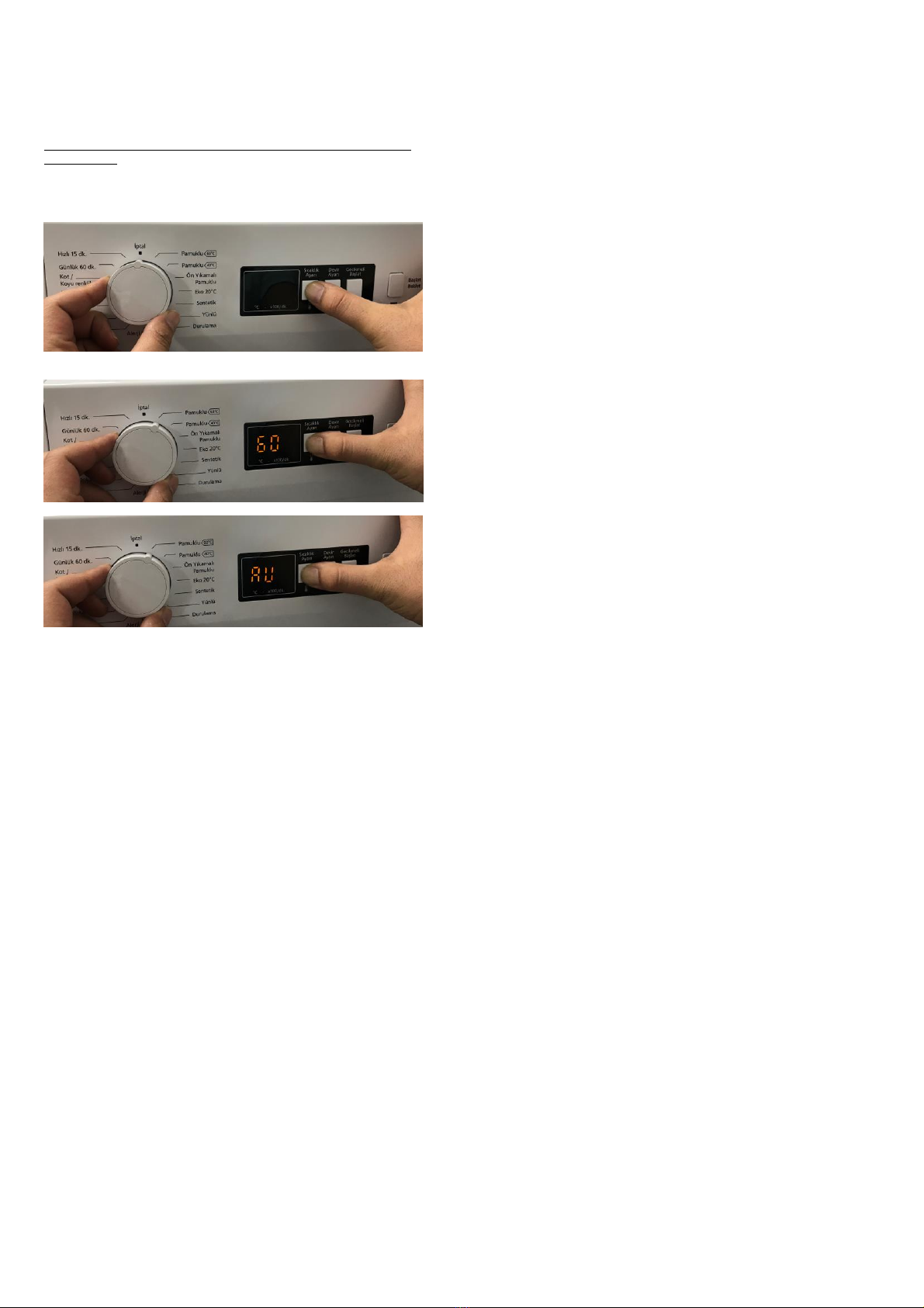
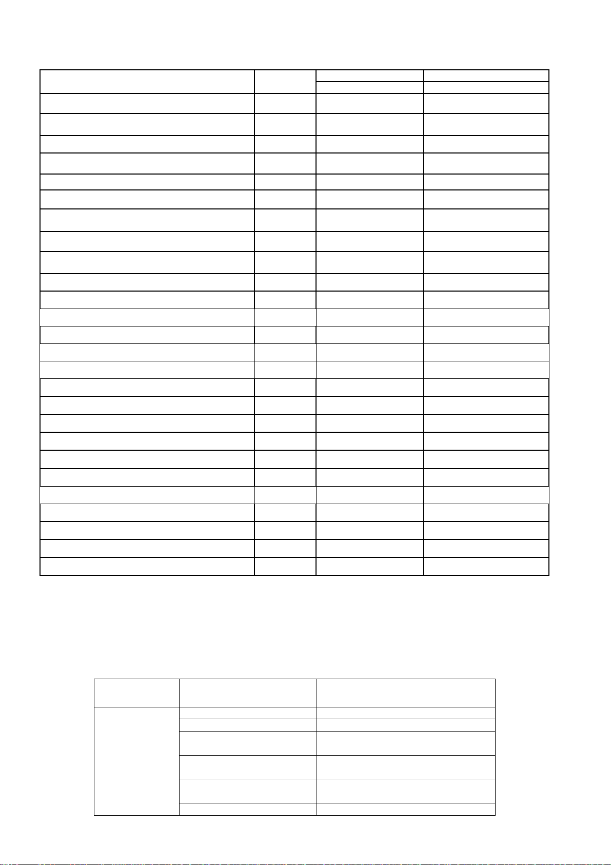
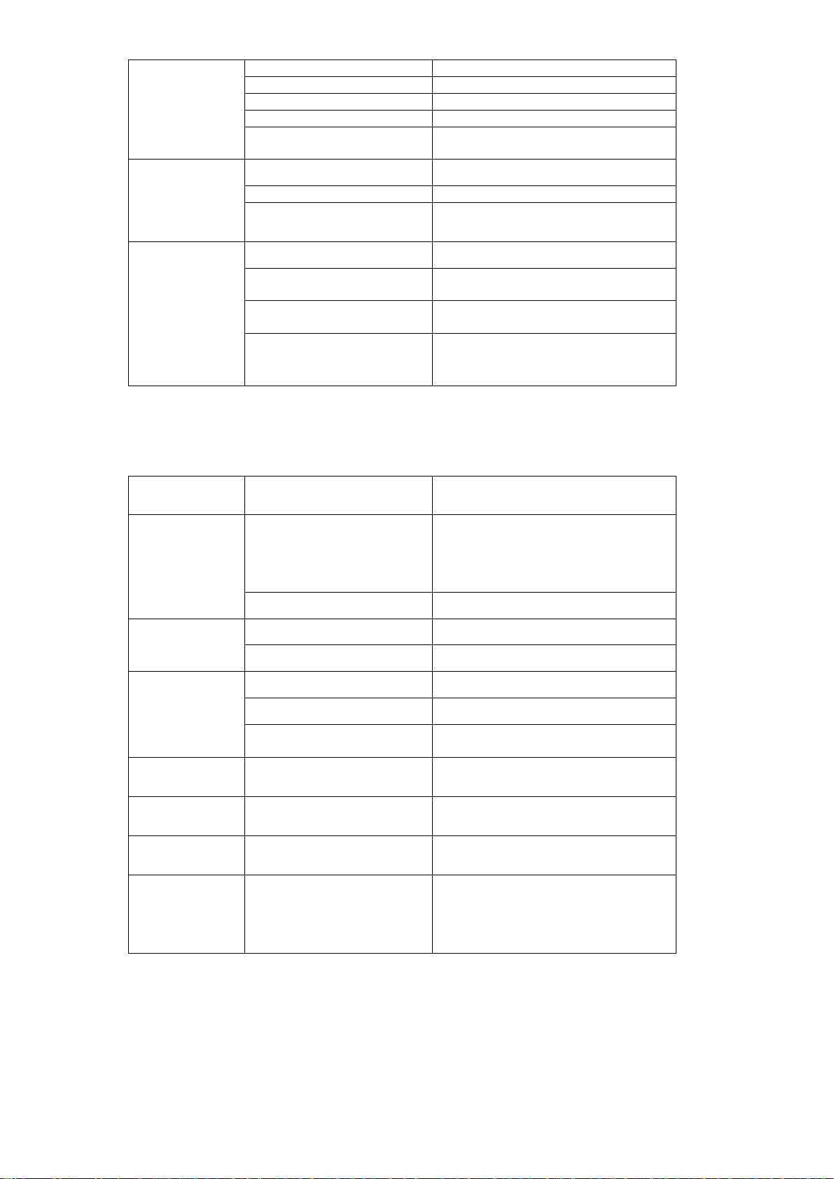
4. Test Mode
4.1. Autotest
* This test is for quick checking of the product. You can not see the
failure codes.
1. Push SW4 button. Keeping SW4 button pushed, turn
program knob to position 1.
2. After 3 sec, door will be locked and machine enters
autotest mode. Release SW4 button. "AU" will be
visualized on LCD.
The test steps are as below;
Step1: The pump is activated for 3 seconds and there is EPS
check , the frequency value should be between the 46.04Hz and
43.40Hz. It checks the EPS and if it is OK it continues the autotest; if
it is NOK then it should give E10 ERROR & cancels the autotest (
goes to the selection mode ). Also if any frequency can not be
detected, then it means there is problem with connection or EPS, so
it gives E10 which is EPS error and cancels the autotest.
Step2: The motor ramps to max spin for 15 seconds. While its
speed rising up to the maximum speed the EV1 (prewash valve) is
activated for 5 seconds and then the EV2 (wash valve) is activated
for 5 seconds.
Step3: The motor reduces speed to stop (depends on the motor
stop time) for 5 seconds. While it is slowing down it activates EV1
and EV2 valve, concurrently.
Step4: The motor turns to right.
Step5: The motor turns to left for 5 seconds.
Step6: The option 1 button is pushed
The EV1 and EV2 are activated concurrently until it reaches
pressure sensor's first level frequency ( Hz ) for 5 seconds.
Step7: Software will detect NTC's resistance value and will check
if the temperature is between 5°C < Tdetected < 40°C . If it is inside
the range, heating step will be done. If temperature value is outside
the range, then it means NTC is detecting the temperature in a
wrong way and heating step will be skipped.
Step8: Autotest ends and "--" is visualized (T0).
Autotest ends and "End" is visualized on LCD (In the rest of the
models).

8
Flow chart of the autotest:
During test “AU” is visualized on display, at the end of the test “--” is visualized and door is unlocked. During test, pressing other buttons makes no change on display.

9
5. Service Mode
5.1. Service Autotest
End users can only see E1-E2-E3-E4. During service autotest, other failures can be seen.
1. To activate service autotest, Press SW3 button and simultaneously position program knob to 1.
2. After 3 sec, door will be locked, and machine enters service autotest mode. Release SW3 button.
In T0 "SA" will be visualized on LCD. In rest of the models "SAU" will be visualized on LCD.
Selector
Position 1
Selector
Position 2
Selector
Position 3
Result
Result
Result
HEATER ON
PUMP ON
RAPID 15' PROGRAM
Comments :
When entering in service
test, door will be locked.
TEST IS OVER Door will be
unlocked, machine will go to
END state.
The test steps are as below ;
Step 1 :
Selector position 1 will be “HEATER ON”
Before heating it should take water till first level frequency then start
heating.
Heater will be on max. 8 minutes.If temperature doesn’t increase 2°C
in 8 minutes,machine will give NTC failure. ( E05 ).
Or if the NTC connection is broken then it should give again E05 NTC
failure.
At the end of heating, "SA" or “SAU” visualization should make slow
blink to indicate that the step is over.
Note : If user changes the selector position, machine will do what is
defined for the new selected position.
Step 2 :
Selector position 2 will be “PUMP ON”
Temperature will be measured, if it is higher than 50°C, it should take
80sec. cooling water and then make "Drain+ 5sec.)
At the end of pump activation, "SA" or "SAU" visualization should
make slow blink to indicate that the step is over.
Step 3 :
Selector position 3 will be “RAPID 15' ”
So machine will make exactly the same algorithm of Rapid 15'.
So, time for selector position 1 is 15 minutes.
At the end of Rapid 15' the door will be unlocked and machine will go
to END mode.
10
5.2. Failure Codes
*Some of the error codes can not be seen based on changing the product types
6. Troubleshooting Guide
All repairs which must be done on the machine should be done by authorized agents only. When a repair is required for machine or you are unable
to eliminate the failure with the help of the information given below:
Unplug the machine.
Close the water tap.
FAILURE
PROBABLE CAUSE
METHODS OF ELIMINATION
Machine does not
operate.
It is unplugged.
Insert the plug into the socket.
Fuse is defective.
Change fuse.
Start / Pause button has not been
pressed.
Press the start / pause button.
The program knob is in 0 (off)
status.
Bring the program knob on the desired status.
The door is not shut properly.
Shut the door properly. You should hear the
click.
Child lock is active.
See page 9.
Error Indication
Error Number
Indication For User
Indication For Service
Yes/No
Yes/No
Door is not locked
E01
Yes
Yes
Door is unlocked during programme
E01
Yes
Yes
Lack of water
E02
Yes
Yes
Pump failure
E03
Yes
Yes
Overflow
E04
Yes
Yes
NTC or Heater Failure
E05
No
Yes
Motor Failure - 1 (Tachometer open-short circuit or motor
connector is disconnected)
E06
No
Yes
Configuration Failure
E07
No
Yes
Motor Triac Failure
E08
No
Yes
Voltage Error
E09
Yes
Yes
Electronic Pressure Sensor
E10
No
Yes
Dryer Card Communication Error
E11
No
Yes
3D Communication Error
E12
No
Yes
LCD Communication Error
E13
No
No
Dryer Resistance Failure
E14
No
Yes
Twinjet Failure
E15
No
No
High Temperature Error
E16
No
Yes
Flowmeter Failure
E17
No
Yes
Dryer NTC Failure
E18
No
Yes
BLDC Failure
E19
No
Yes
Pyrojet Failure
E20
No
Yes
Detergent Dosage Pump Failure
E21
No
Yes
Softener Dosage Pump Failure
E22
No
Yes
Communication Failure Between PCB and BLDC Card
E23
No
Yes
Wrong LCD Software
E50
No
Yes
Wrong BLDC Software
E51
No
Yes
11
Machine does not
receive water.
Water tap is closed.
Open water tap.
The water inlet hose may be bent.
Check the water inlet hose.
The water inlet hose is obstructed.
Clean the filters of water inlet hose.
The water inlet filter is obstructed.
Clean the valve inlet filters.
The door is not shut properly.
Shut the door properly. You should hear the
click.
Machine is not
draining water.
The drain hose is obstructed or
bent.
Check the drain hose.
The pump filter is obstructed.
Clean the pump filter.
The clothes are not placed inside
the machine in a well-balanced
manner.
Spread the clothes inside the machine in an
orderly and well-balanced manner.
Machine is
vibrating.
The feet of machine are not
adjusted.
Adjust the feet.
Transportation screws are not
removed.
Remove transportation screws.
There is a small amount of clothes
in the device.
It does not prevent operation of the machine.
Excessive amount of clothes are
filled in the machine or the clothes
are not placed in a well-balanced
manner.
Do not exceed the recommended quantity of
clothes and spared clothes in the machine in a
well-balanced manner.
FAILURE
PROBABLE CAUSE
METHODS OF ELIMINATION
Excessive foam in
the detergent
drawer
Too much detergent has been
used.
Press the start/pause button. In order to stop
the foam, dilute one table-spoon of softener in
half liter of water and pour it in the detergent
drawer. Press the start/pause button after 5-10
minutes. Arrange the amount of the detergent
properly in the next washing process.
Wrong detergent has been used.
Use only the detergents produced for full
automatic machines.
The washing result
is bad.
Laundry too dirty for the program
you have selected.
Select a suitable program.
The amount of detergent used is
not sufficient.
Use more detergent according to the
detergent.
The washing result
is not good.
Clothes exceeding the maximum
capacity has been filled in machine.
Put the clothes in machine in a manner not to
exceed its maximum capacity.
Water may be hard.
Use the amount of detergent according to the
declaration of the detergent producer.
Distribution of the clothes in
machine is not well-balanced.
Spread the clothes inside the machine in an
orderly and well-balanced manner.
The water is seen
in the drum during
washing.
No failure. The water is at the lower
part of the drum.
There are residues
of detergent on the
clothes.
The pieces of some detergents
which do not dissolve in water may
stick to clothes as white stains.
By calibrating machine for “Rinsing” program,
make an additional rinsing or eliminate the
stains After drying with the help of a brush.
There are grey
stains on the
clothes.
These stains may be caused by oil,
cream or ointment.
In the next washing operation, use the
maximum detergent amount declared by the
detergent producer.
The spinning
process is not done
or starts with delay.
No failure. The unbalanced load
control works in that way.
The unbalanced load control system will try to
distribute clothes in a homogenous manner.
After clothes are distributed, passage to
spinning process will be realized. In the next
washing process, place clothes into the
machine in a well-balanced manner.

25
8. Component Specifications
8.1. Drain Pump
Drain pump is both a mechanical and elektrical component which is used to drain
water inside the washing machine. It has an synchronous motor inside. For
better performance maintanance, pump filter should be cleaned regularly.
8.1.1. Technical Features
Nominal voltage 220 - 240 V
Nominal current 0.28 A (±10 %)
Nominal power 37 W
Frequency 50 Hz
Resistor (coil) 130 Ω (±5%)
Water flow: 17 L/min(to 1 m height)
Thermal protector YES
8.1.2. Checking of Component
Check the resistance value on the component with multimeter as shown in belows figures.
Resistance value should be between 125- 140 Ω
Checking the component

26
8.2. Resistance
Heating element (Resistance) is a component which is desingned to regulate
temperature of water inside the drum. It has three connections: Phase, notral and
ground connections.
8.2.1. Technical Features
Kind of heating Tubular heating element with NTC –sensor
Nominal voltage 230 V
Nominal power 2000 W (±5%)
Resistance 24,8 ±5% Ω
Thermal fuse 2 –sided
8.2.2. Checking of Component
Check the resistance value on the component with multimeter as shown in below pictures.
Checking the component
27
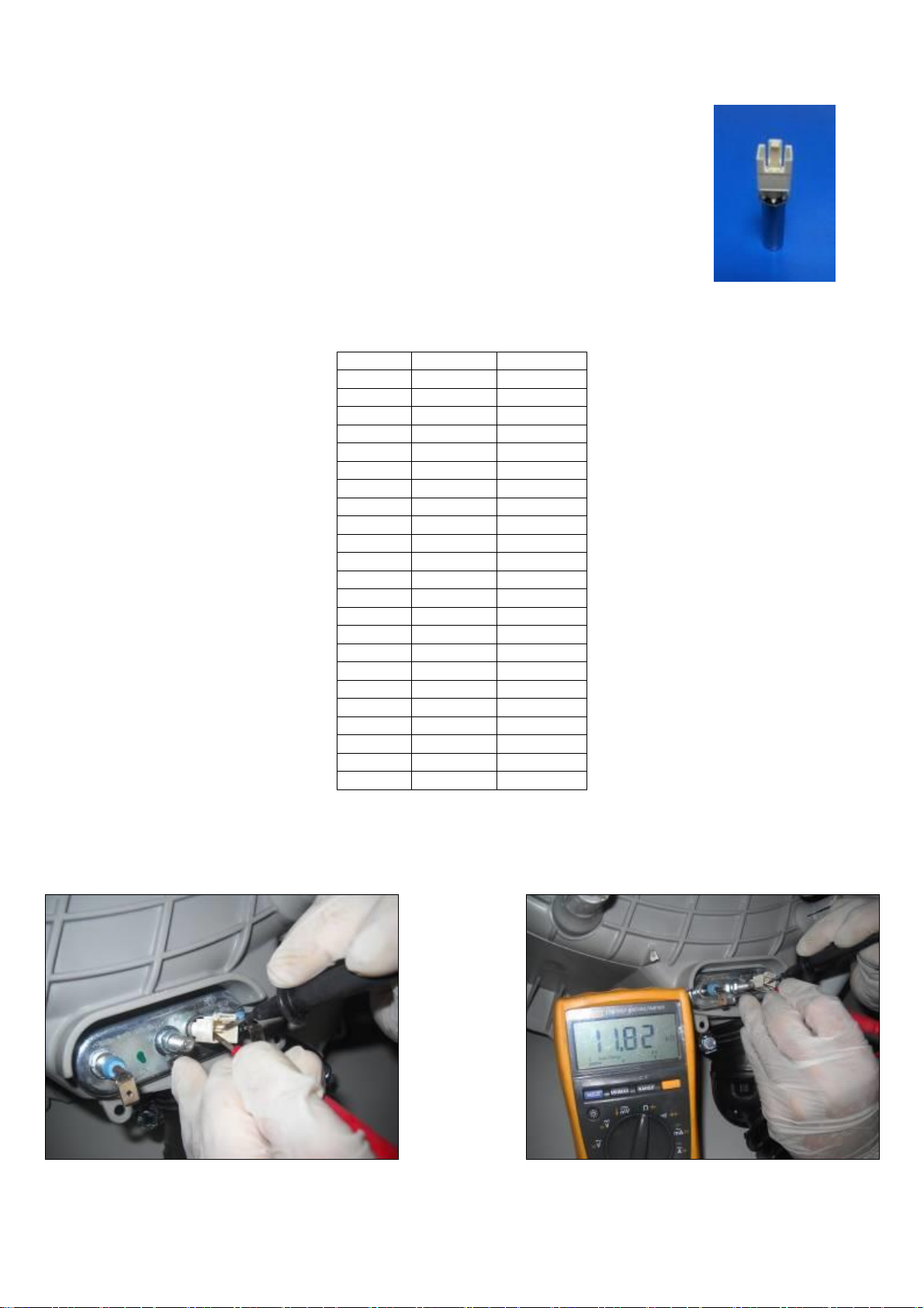
8.3. NTC
Component which sends signals to PCB about the water temperature inside the tub.
The Resistance (Ohm) value of the NTC decreases as the temperature increases.
8.3.1. Technical Features
Tem (°C)
R min (kΩ)
R max (kΩ)
-10
54,9
62,6
-5
43,0
48,6
0
33,9
38,1
5
27,0
30,1
10
21,6
23,9
15
17,4
19,1
20
14,1
15,4
25
11,5
12,5
30
9,4
10,2
35
7,8
8,3
40
6,4
6,9
45
5,4
5,7
50
4,5
4,7
55
3,8
3,9
60
3,2
3,3
65
2,7
2,8
70
2,3
2,4
75
1,9
2,0
80
1,7
1,8
85
1,4
1,5
90
1,2
1,3
95
1,1
1,1
100
0,9
1,0
NTC Tempure –Resistance Values
8.3.2. Checking of Component
Check the resistance value on the component with multimeter as shown in below pictures.
Checking the component
28
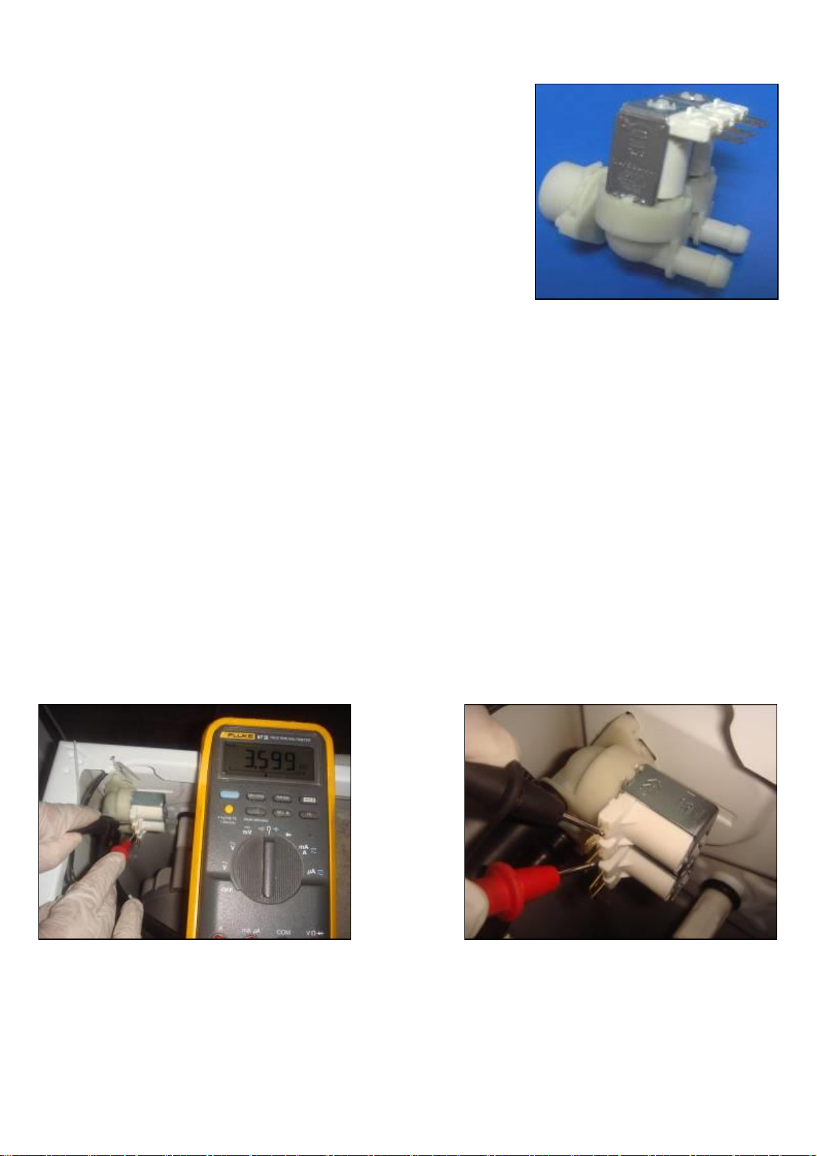
8.4. Valve
Valve is an electrical and mechanical component which is designed to take water from the network
system into the washine machine. It is operated by PCB card.
8.4.1. Technical Features
Nominal voltage 220 –240 V
Nominal power 8 VA
Frequency 50-60 Hz
Rated flow: 7 lt/min (±15 %)
Operating water pressure 0.0,3 –1 Mpa
8.4.2. Checking of Component
Check the resistance value on the component with multimeter as shown in below pictures.
Valve water flow rate should be between 6 lt/min - 8 lt/min.
Each valve bobbin resistance values should be between 3,3 - 4.2 kohm .
Checking the component

29
8.5. Electronic Pressure Switch (EPS)
8.5.1. Technical Features
Electromagnetic field occurs as a result of the vibration of the membrane which is under pressure in the coil. The nucleus part is moved up and down by
the electromagnetic field. The water level is regulated by the frequency which is controlled by the PCB and changes according to the movement of the
nucleus part.
8.5.2. Checking of Component
1. Make sure there are no laundry in washing machine, tap is connected and opened, power cord is plugged. Put no detergent in drawer.
2. Bring porgram knob to position 1 (Cotton 90°C program)
3. Press start button.
4. Wait for water intake step to finish. You can recognise it by listening the water sound or slightly opening and observing detergent drawer.
5. As soon as water intake is over turn program knoc to position 0 (Off position)
6. Check water level from door glass. The water level should be just below door glass as seen in the picture below: (There is a %10 tolerance
with this level)
30
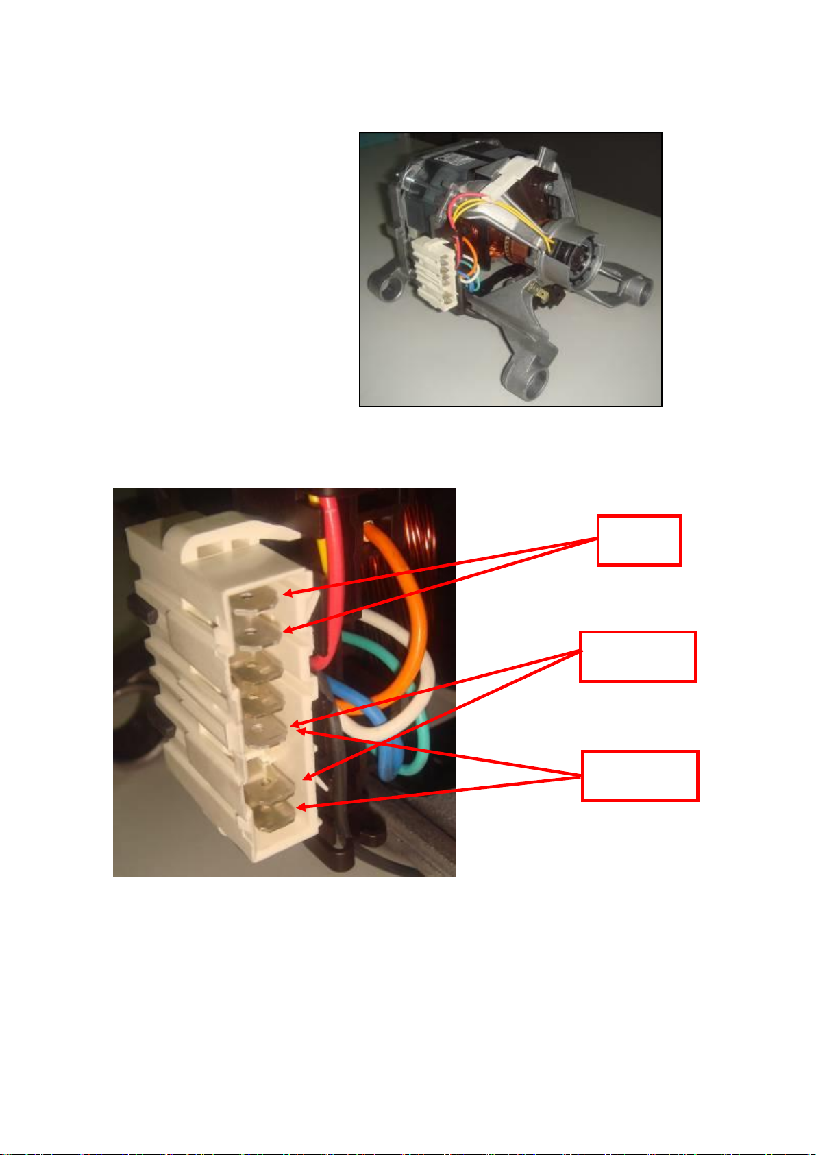
8.6. Motor
The washing machine has an asynchronous motor. t is controlled by the
PCB.
It is essential to check the motor for correct diagnosis and quick servicing.
In the below picture, socket points on the motor is shown to measure with
multimeter.
Motor Socket Terminals
Tacho
Socket
Terminal
Stator Full Field
Coil Socket
Terminal
Stator Half Field
Coil Socket
Terminal
31
Tacho and stator (full field-half field) ohm resistance values for the motor types are listed in the below table.
MOTOR CODE
SUPPLIER
STATOR
AUXILIARY WINDING
TAKO
Resistance
Resistance
Resistance
32016268
WELLING
2,00 ± %7 Ω
NA
66,6± %7 Ω
32030654
G&J
1,86-2,14 Ω
NA
60,69-69,83 Ω
32016267
WELLING
1,45 ± %7 Ω
NA
66,6± %7 Ω
32031898
G&J
2,10-2,42 Ω
NA
60,69-69,83 Ω
32030127
WELLING
1,68 ± %7 Ω
NA
66,6± %7 Ω
32028497
NIDEC
1,63 ± %7 Ω
0,82 ± %7 Ω
184 ± %7 Ω
32028498
WELLING
1,377 ± %7 Ω
0,785 ± %7 Ω
66,6 ± %7 Ω
32030432
WELLING
1,68 ± %7 Ω
1,55 ± %7 Ω
66,6± %7 Ω
32017283
WELLING
1,93 ± %7 Ω (AL)
NA
66,6± %7 Ω
32013652
HAIER
2,65 ± %7 Ω
NA
68,8 ± %7 Ω
32032079
TONLON
2,28 ± %7 Ω
NA
70,2± %7 Ω
32030653
G&J
2,28-2,63 Ω
NA
60,69 - 69,83 Ω
32037679
KENING
2,10 ± %7 Ω
NA
63,6± %7 Ω
32031043
G&J
2,03-2,34 Ω
NA
60,69 - 69,83Ω
32027577
WELLING
2.39±7%Ω
NA
66,6±7%Ω
32027576
HAIER
2.36±7%
NA
68,8± %7 Ω
32019342
WELLING
2,00 ± %7 Ω
NA
66,6± %7 Ω
32034697
G&J
1,82 ± %7 Ω
NA
65,26± %7 Ω
32032630
HAIER
1,27 ± %7 Ω
NA
68,8± %7 Ω
32019343
WELLING
1,67 ± %7 Ω
NA
66,6± %7 Ω
32034698
G&J
1,82 ± %7 Ω
NA
65,26± %7 Ω
32031529
HAIER
1,27 ± %7 Ω
NA
68,8± %7 Ω
32004905
NIDEC
2,70 ± %7 Ω
1,04 ± %7 Ω
184 ± %7 Ω
32027578
WELLING
1,21 ± %7 Ω
NA
66.6 ± %7 Ω
32025348
NIDEC
1,72 ± %7 Ω
0,70 ± %7 Ω
184 ± %7 Ω
32028496
ANAIMEP
1,36 ± %7 Ω
0,70 ± %7 Ω
180 ± %7 Ω
32030431
NIDEC
1,50 ± %7 Ω
0,75 ± %7 Ω
184 ± %7 Ω
32033330
WELLING
1,38 ± %7 Ω
0,761 ± %7 Ω
66,6± %7 Ω
32030003
NIDEC
2,25 ± %7 Ω
1,03 ± %7 Ω
184 ± %7 Ω
32028925
NIDEC
2,70 ± %7 Ω
1,14 ± %7 Ω
184 ± %7 Ω
32033617
WELLING
2,04 ± %7 Ω
0,99± %7 Ω
66,6 ± %7 Ω
Resistance values for the motor types
32
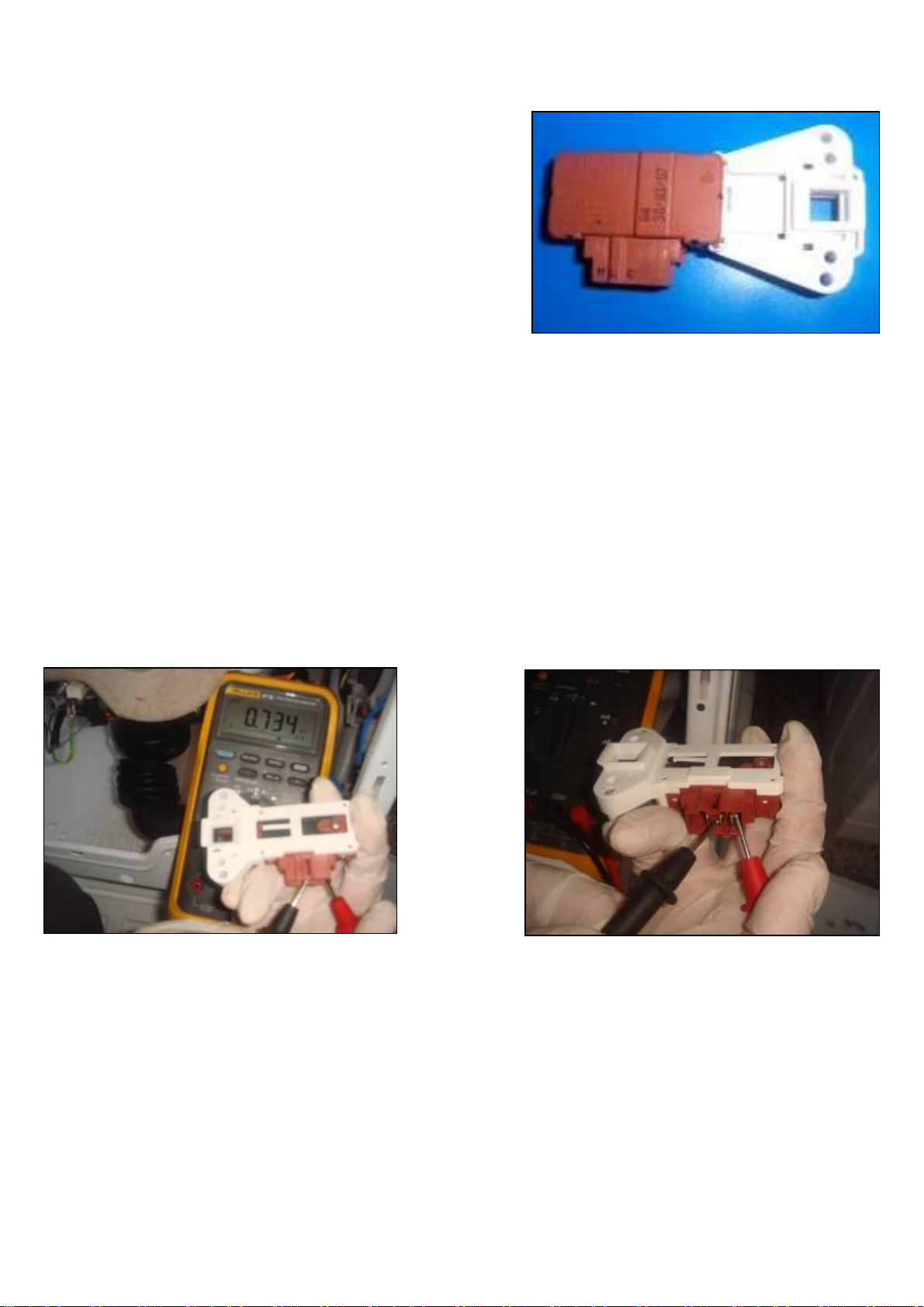
8.7. Door Lock
Door lock is activated at the beginning of the program in order to prevent the door
from opening. It can be unlocked approximately after 2 minutes of the program end.
This time delay is caused by the PTC which is assambled in the door lock.
8.7.1. Technical Features
Lock Time (20 °C) 2” – 6”
Unlock Time (20 °C) 35” – 75”
Nominal voltage 220 V
Nominal current 16 (4) A
8.7.2. Checking of Component
Check the resistance value on the component with multi-meter as shown in below figures.
Resistance value on the PTC should be 1000 Ω ±50% at 25 °C. That resistance value can be measured from terminal 3-4 (See wiring diagram page 51
below).
2
3
4
5
Table of contents
Other SOGEDIS Washer manuals


