SOGEDIS D4 Series User manual

Manuel de service
Séries D4

Table of Contents
1. Safety Precautions ..................................................................................................................................................4
2. Specifications..........................................................................................................................................................5
3. Control Panel and Acronyms ...................................................................................................................................6
4. Test Mode...............................................................................................................................................................7
4.1. Autotest.......................................................................................................................................................................... 7
5. Service Mode ..........................................................................................................................................................9
5.1. Service Autotest............................................................................................................................................................... 9
5.2. Failure Codes .....................................................................................................................................................10
6. Critical Torque Values ...........................................................................................................................................10
7. Disassembly and Assembly Instructions.................................................................................................................11
7.1. Top Plate ....................................................................................................................................................................... 11
7.2. Door.............................................................................................................................................................................. 11
7.3. Spring Wire.................................................................................................................................................................... 12
7.4. Detergent Drawer.......................................................................................................................................................... 12
7.5. Control Panel................................................................................................................................................................. 13
7.6. Electronic Card & Fuse ................................................................................................................................................... 14
7.7. Front Panel .................................................................................................................................................................... 15
7.8 Dryer Card ...................................................................................................................................................................... 16
7.9 Dryer Unit....................................................................................................................................................................... 16
7.10 Support Bracket............................................................................................................................................................ 18
7.11 Detergent Drawer Housing............................................................................................................................................ 18
7.12 Power Cable Group and EMI Filter................................................................................................................................. 18
7.13 Electronic Pressure Switch (EPS).................................................................................................................................... 19
7.14 Door Lock* ................................................................................................................................................................... 19
7.15 Drain Pump................................................................................................................................................................... 20
7.16 Front Counterweight*................................................................................................................................................... 20
7.17 Heater .......................................................................................................................................................................... 20
7.18 Tub Bellow Seal*........................................................................................................................................................... 21
7.19 Transport Screw............................................................................................................................................................ 21
7.20 Upper Counterweight* ................................................................................................................................................. 21
7.21 Washing Group............................................................................................................................................................. 22
7.22 Shock Absorber Pin....................................................................................................................................................... 22
7.23 Driven Pulley................................................................................................................................................................. 22
7.24 Driven Pulley................................................................................................................................................................. 22
7.25 Motor........................................................................................................................................................................... 23
7.26 Tub............................................................................................................................................................................... 23
8. Component Specifications.....................................................................................................................................24
8.1. Drain Pump.................................................................................................................................................................... 24
8.2. Heater ........................................................................................................................................................................... 25
8.3. Washer NTC................................................................................................................................................................... 26
8.4. Valve ............................................................................................................................................................................. 27
8.5. Electronic Pressure Sensor (EPS)* .................................................................................................................................. 28
8.6. Motor............................................................................................................................................................................ 29
8.7. Door Lock* .................................................................................................................................................................... 30
8.8. Fan Group...................................................................................................................................................................... 31
8.9. Dryer Heater.................................................................................................................................................................. 32
8.10. Dryer NTC .................................................................................................................................................................... 33
8.11 Component Control on PCB........................................................................................................................................... 34
9. Wiring Diagram* ...................................................................................................................................................37
10. Troubleshooting..................................................................................................................................................38

About Content
This service bulletin is prepared for all OEM products within D4 range. Therefore you may encounter information
about some optional components that may not exist in your product. As this is a generic service bulletin covering all
range, please ignore and skip extra/optional component information. Sections marked with asterisk (*) sign contain
information about optional components.
Information already exists in user manuals is not included in this service manual. Please refer to user manual of your
product for basic installation, operating, maintenance and troubleshooting issues.
Contact
For your inquiries please send an email to:
WashingMachineCustomerSupport@vestel.com.tr
You can also open a support ticket using Service Support Page:
https://www.vestelservice.com/VestelService/
Acronyms:
WM : Washing Machine
W&D : Washer & Dryer
WMCS : Washing Machine Customer Support
TJ : Twinjet
UI : User Interface
SI : Service Interface
A : Available
NA : Not Available
1. Safety Precautions
Important:
This service information is designed for experienced repair technicians only and is not designed
for use by the general public. It does not contain warnings or cautions to advise non-technical
individuals of potential dangers in attempting to service a product. Products powered by
electricity should be serviced or repaired only by experienced professional technicians. Any
attempt to service or repair the product or products dealt with in this service information by
anyone else could result in serious injury or death.
Warning:
Before any disassembly/repair operation make sure appliance is unlplugged water tap is closed
and heating elements are cooled down. There is electrical shock, burning and flood risk.
Warning:
Please replace whole cable group even in case there is any minor failure with cables / terminals /
sockets. Never try to repair nor to solder cable group. It may cause smoke, ignition and there is
major risk of electrical shock.
Important:
Always use insulator gloves to prevent injury by metal edges or to prevent electrical shock during
electrical tests.
Work with uniforms having long sleeves to protect your arms from metal edges.
Always use original spare parts. You may harm appliance, end user, environment or yourself
using untested and unapproved 3rd party spare parts.
Use right tools to prevent any wear or damage to components during assembly/disassembly.

2. Specifications
Here you will find descriptions of generic specifications for the range specified for this service manual. Please refer to
product fiche and user manual for detailed technical specifications.
*Twinjet System:
Twinjet system is designed to obtain a better washing performance by directly injecting water
with detergent using a recirculation system and two nozzles connected to it. With twinjet
system, water consumption is decreased by 30%, energy consumption is decreased by 10% and
washing time is decreased by 15%
Twinjet system is valid for all programs except spin and drain mode. The system dos not function
during Water inlet, heating, spinning, drain phases.
Even with a large load of 8 kg. the washing machine will have the minimum energy consumption
by the help of Twinjet system.
Washing machines with Twinjet system are very environment-friendly by having maximum
washing performance with minimum water consumption.
Eco-Logic System:
Half load detection system, thus using less water and power accordingly. This system is available
for cotton programs only.
Foam Protection System:
Foam Protection System is a safety algorithm that interrupts normal program flow and reduces
foam level by taking water and draining. This algorithm protects machine and environment
avoiding over foaming inside tub in case any customer misuse such as detergent overdose or use
of foamy cleaning agents.
Overflow Protection System:
Overflow protection is another safety algorithm in case of a flood risk. If there is more water in
tub than expected by algorithm, it will start to the drain routine giving E04 failure code. For
example this may happen in case of a valve failure and the machine constantly takes water. This
algorithm will keep drain routine, keeps water leveled and protects environment and machine
avoiding any flood risk.
Unbalanced Load Detection and Control System:
Unbalance Control System is another safety algorithm that protects the machine and
environment avoiding machine movement due to vibration during spinning profile. The
algorithm tries to balance load by a special balancing agitation, postponing spin profile till it is
balanced. This avoids spinning while load is unbalanced and prevents any possible physical harm
both to the appliance and to surroundings.
3. Control Panel and Acronyms
PR
Program selector 16 programs including off position
SW1
Switch 1, Start / Pause
SW2
Switch 2, Option 1 (Delay Timer)
SW3
Switch 3, Option 2 (Drying Level)
SW4
Switch 4, Spin Speed Selection
SW5
Switch 5, Temperature Selection
L1
LED 1, Start/Pause LED
L2
LED 2, Drying Level 1 LED
L3
LED 3, Drying Level 2 LED
L4
LED 4, Drying Level 3 LED
L5
LED 5, Drying Level Option LED
L6
LED 6, Delay Time LED
PR
SW5
SW4
SW3
SW2
SW1

4. Test Mode
4.1. Autotest
4.1.1. Autotest Steps
1. Press and hold SW5.
Autotest follows a predefined flowchart in order. Unlike
service autotest, autotest automatically skips to next step
upon completing one. The steps of the test are as follows:
Step1:
The drain pump is checked.
Step2:
Motor ramps to max spin speed while valves are activated
in order.
Step3:
Motor stops, both valves are activated simultaneously.
Step4:
The motor turns to right. Also, dryer valve is activated.
Step5:
The motor turns to left.
Step6:
Both valves are activated. (Water intake for heating)
Step7:
Washer NTC is checked.
Step8:
Washer Heater is checked.
Step9:
Dryer resistance I and I&II are checked.
Step10:
Dryer NTC is checked for 2sec.
Step11:
Fan is checked.
In case of no failure test ends after this step and “End” is
displayed. In case of an error detection EXX and error
definition will pop up on display. (where XX is the error
number 1 to 10 )
Please see following autotest chart for details.
2. While pressing SW5, turn PR to 1st position
(Cotton). Wait 3 seconds and release SW5. During
test “AU” is visualized on display.
3. When autotest is finished, END screen is
visualized.
30
35
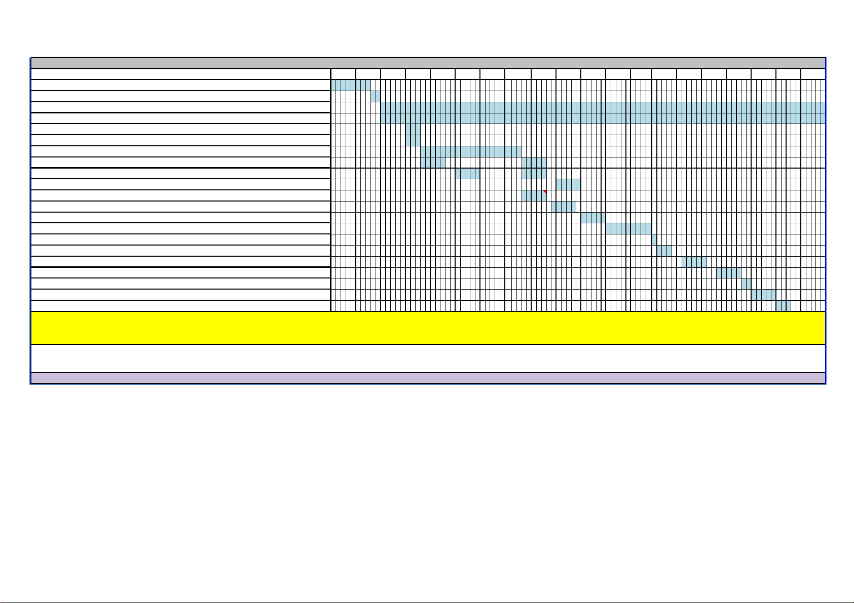
AUTOTEST
90
95
40
45
50
55
60
65
75
80
85
Time in seconds (to be adjusted)
5
10
15
20
25
EV1 + EV2 valves up to first level frequency (Depends on the water level)
Washer NTC check
Washer heater resistance
EPS measurement
Motor Ramp to max spin (max. is 20 sec.)
EV1 (flowrate dependent of washer)
EV2 (flowrate dependent of washer)
Dryer valve
Time until motor is stopped (Depends on the motor stop time)
Motor Preferred Run (Direction to Right)
Motor Inverse Run (Direction to Left)
100
Entering autotest
Changing power to 220 50Hz
Main Voltage 50 Hz
Door Lock Powered (Depends on door lock)
Pump
70
EPS measurement: It checks the EPS and if it OK, it continues the autotest; if it is NOK then cancel the Autotest and go to the selection mode. Also if any frequency can not be detected, then it means there is problem with connecion
or EPS, so it gives E10 which is EPS error and cancels the autotest & goes to the selection mode.
Dryer Ntc detection : Software will detect NTC's resistance value and will check if the temperature is between 0°C < Tdetected < 50°C. If it is inside the range, heating step will be done.
Washer Ntc detection : Software will detect NTC's resistance value and will check if the temperature is between 5°C < Tdetected < 40°C. If it is inside the range, heating step will be done.
If temperature value is outside the range, then it means NTC is detecting the temperature in a wrong way and heating step will be skipped. Additionally if NTC connector disconnected it should shows NTC failure code(E05) on display.
Dryer resistance I
Dryer resistance I + II
Dryer NTC
Fan
End Visualization

5. Service Mode
5.1. Service Autotest
5.1.1. Service Autotest Steps
1. Press and hold SW4.
If you turn knob position to other program between 1st to
3rd it will skip current test and start the selected one. It is
recommended not to skip any steps for a detailed
checkup. Unlike autotest, service autotest starts next test
step manually by rotating program selection knob.
Step1:
There will be a certain amount of water intake and then washer heater is
activated for 8 minutes. Washer NTC values are checked in this period.
In case of a washer heater/NTC failure, it pops up E05 error displaying
“E05” on SW3.
At the end of heating, "SAU" visualization should make slow blink to
indicate that the step is over. You can turn program knob to 2nd position
to continue with step2.
*During this step if EPS detects high water level, overflow algorithm is
applied and E04 is released.
Step2:
Drain pump is activated; in case of a pump failure it pops up E03 error.
At the end of pump activation, "SAU" visualization should make slow
blink to indicate that the step is over. You can turn program knob to 3rd
position to continue with step3.
Step3:
Dryer Heater I and fan is activated. After 3 mins if there will be no
temperature change (ΔT< 10°C), it will release E14 failure.
If temperature increases accordingly (ΔT > 10°C), "SAU" visualization
should make slow blink to indicate that the step is over. You can turn
program knob to 4th position to continue with step4.
Step4:
Dryer Heater II and fan is activated. After 3 mins if there will be no
temperature change (ΔT< 10°C), it will release E14 failure.
If temperature increases accordingly (ΔT > 10°C), "SAU" visualization
should make slow blink to indicate that the step is over. You can turn
program knob to 5th position to continue with step5.
Step5:
Rapid 15’program algorithms is run to test all washing components, the
only difference is error codes are displayed which normally are not
displayed to end user.
If no error found in test program ”SAU" visualization should make slow
blink to indicate that the step is over. You can turn program knob to 6th
position to continue with step6.
Step6:
A 5 mins drying program is run to test all drying components.
If case of no error service autotest ends and "End" is displayed.
*If user changes the selector position, machine will do what is defined
for the new selected position.
2. While pressing SW4, turn PR to 1st position
(Cotton). Wait 3 seconds and release SW4. Step 1 of
service autotest will start. During test “SAU” is
visualized on display. Please see details about steps
in right column.
3. When autotest is finished, END screen is
visualized.

5.2. Failure Codes
Error Indication
Error Number
Indication in UI
Indication in SI
Door/Door Lock Failure
E01
A
A
Lack of water
E02
A
A
Pump failure
E03
A
A
Overflow
E04
A
A
NTC or Heater Failure
E05
NA
A
Motor Failure
E06
NA
A
Configuration Failure
E07
NA
A
Motor Triac Failure
E08
NA
A
Voltage Error
E09
A
A
Electronic Pressure Sensor
E10
NA
A
Dryer Board Connection Failure
E11
NA
A
Dryer Thermostat Failure
E14
NA
A
Twinjet Failure
E15
NA
A
Dryer Overheated Failure
E16
NA
A
Flowmeter Failure
E17
NA
A
Dryer NTC Failure
E18
NA
A
6. Critical Torque Values
Assembly Locatıon
Bolt/Nut/Screw
Torque
Min. (Nm)
Torque
Nom. (Nm)
Torque
Max.
(Nm)
Air Pressure
Wrench
Speed (rpm)
*
Transport Screw Assembly
Transport Screws
6.50
6.50
7.00
1000
*
Motor Assembly
Motor Screws
6.00
6.50
7.50
800
*
Front Concrete Weight - Front
Tub Assembly
Front Counterweight
Screws
14.00
14.50
14.75
600
*
Upper Counter Weight
Assembly
Upper Counterweight
Screws
25.00
27.50
30.00
440
*
Pulley –Drive Shaft –
Washing Group Assembly
Pulley –Drive Shaft
Assembly Bolt
39.50
40.00
40.50
440
*
Washer Heater Assembly
Heater Assembly Nut
3.85
4.00
4.00
970
The bolts/nuts above are important for product safety purposes. Please tighten screw, bolts and nuts
according to the torque values given in table above.
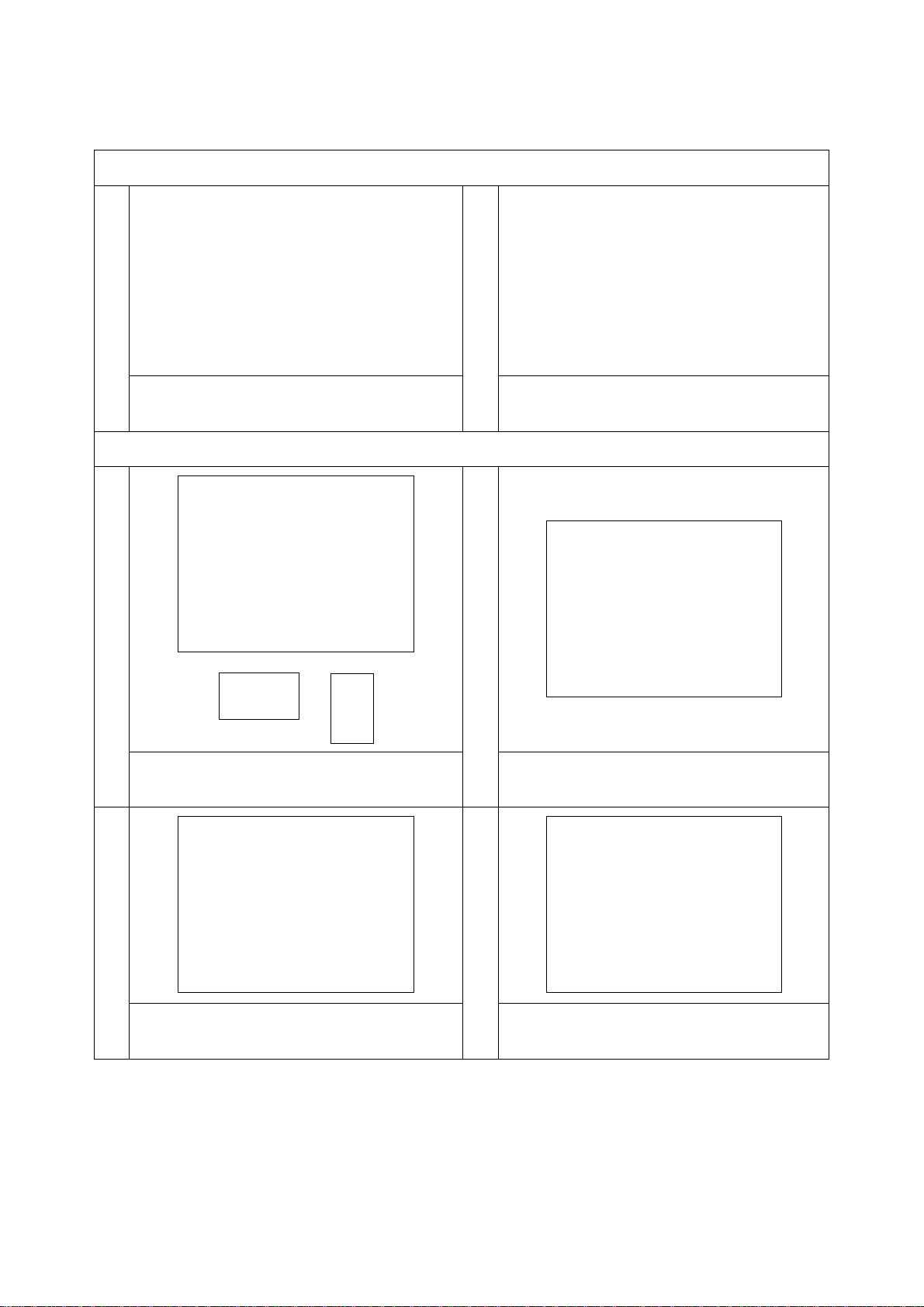
7. Disassembly and Assembly Instructions
7.1. Top Plate
1
2
Remove two screws that fix the top-plate at
the back.
Push the top-plate back and pull it up.
7.2. Door
1
2
Remove two screws that fix the door. (by
using T25 tool)
Pull the door up.
3
4
Remove screws that fix the door group.
Put the door outside plastic with helping
screwdriver.
T25

5
6
Remove the door inside plastic.
Remove six screws that fix the door hinge.
7*
8*
Remove the door handle.
Remove the door handle pin.
7.3. Spring Wire
1
2
First, remove the spring wire fixing the tub
bellows seal by using the small size screw
driver. Pull the tub bellows seal.
Remove the tub bellows seal-body fixing
spring.
7.4. Detergent Drawer
1
2
Gently pull the detergent drawer.
While pressing siphon cover keep pulling
drawer to remove it.

7.5. Control Panel
1
2
Remove the screw which fixes the control
panel to the front panel.
Remove two screws fixing control panel.

3
4
Pull the control panel out.
Remove connectors.
5
6
Remove electronic card cover as it is shown
in the pictures by using small screw driver.
Remove the PCB card box from the control
panel.
7.6. Electronic Card & Fuse
1
2
Remove PCB box using a small screw driver.
3
4
Unplug display card connector.
Open fuse box and remove the fuse.

7.7. Front Panel
1
2
Remove the screw fixing the front panel at
the bottom
Remove two screws fixing the door lock
3
4
Remove the tub bellows seal.
5
6
Remove two screws fixing front panel to
body
Remove the screw fixing twinjet elbow
7
8
Pull front panel up
Remove front panel

9
10
Remove the screw that fixes the pump filter
cover.
Release the holder of the pump filter cover.
7.8 Dryer Card
1
2
Remove the screws that fixes the dryer card
Remove the sockets.
7.9 Dryer Unit
1
2
Remove the screws that fixes the heater unit
of the dryer
Remove the sockets of the heater unit

2
3
Remove the screws that fix the fan group.
Release the cable group by cutting the cable
connection.
4
5
Remove the Cable group of the dryer unit
Remove the sockets of the heater group
6
7
Remove the sockets of the fan group.
Remove the screws that fix the fan group.
8
9
Cut the connection plastic of the dryer unit.
Cut the cable connection of the dryer NTC
and remove the sockets.

7.10 Support Bracket
1
2
Remove two screws fixing the body group on
the upper part
Remove two clips fixing detergent drawer
housing to upper support bracket
7.11 Detergent Drawer Housing
1
2
Remove the tub bellow hose by releasing the
holder extensions of bellow hose
Unplug connectors from feed valve
3
4
Slightly turn the feed valve counter-
clockwise to remove
Remove the detergent drawer housing
assembly
7.12 Power Cable Group and EMI Filter
1
2
Remove the five conectors that is connected
to the EMI filter
Remove two screws fixing EMI filter.

3
4
Pull the power cable group up
Remove EMI filter
7.13 Electronic Pressure Switch (EPS)
1
2
Unplug EPS connector
Pull EPS up
3
Remove clamp from EPS hose
7.14 Door Lock*
1
Unplug door lock connector

7.15 Drain Pump
1
2
Remove clamp holding drain hose by using
a plier
Remove clamp fixing tub outlet hose
3
4
Unplug drain pump connector
Remove screws holding drain pump
7.16 Front Counterweight*
1
2
Remove three screws on the front
counterweight. (Wrench size 13 mm)
Gently pull counterweight out
7.17 Heater
1
2
Unplug heater connectors
Remove nut (8 mm) fixing the heater
Other manuals for D4 Series
1
Table of contents
Other SOGEDIS Washer manuals


