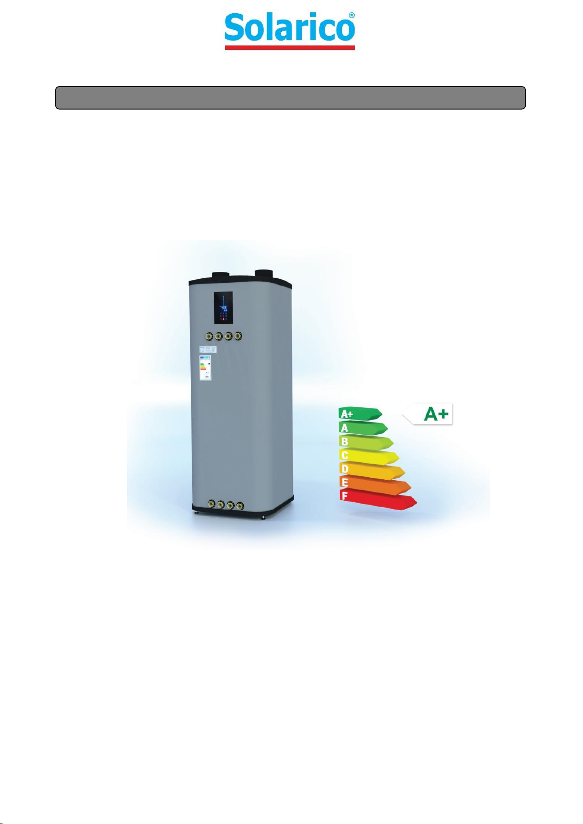
Solarico UniQube 310 Mounting instructions
INSTALLATION, MAINTENANCE AND USER MANUA
L
UniQube Heat Pump
V2.2_2017

Manuals are made for different series of devices. Because of that reason there could be some differences between real
parameters, dimensions or pictures.
We reserve the right to change the technical or any other specifications without notice and without liability. We do not
take responsibility for typographical errors.

CONTENT:
1BASIC INFORMATION __________________________________________________________________________ 1
2SAFETY WARNINGS ___________________________________________________________________________ 1
3IMPORTANT WARNINGS _______________________________________________________________________ 2
4PURPOSE OF THE DEVICE _______________________________________________________________________ 4
5RESPONSIBILITY ______________________________________________________________________________ 4
5.1 Producer responsibility ____________________________________________________________________ 4
5.2 Installer responsibility _____________________________________________________________________ 4
5.3 User responsibility ________________________________________________________________________ 4
6REFRIGERANT ________________________________________________________________________________ 4
7RECYCLING __________________________________________________________________________________ 5
8UNIT SPECIFICATIONS__________________________________________________________________________ 5
9TRANSPORT AND DEPOT _______________________________________________________________________ 6
10 UNIT DIMENSIONS __________________________________________________________________________ 7
11 UNIT INSTALLATION _________________________________________________________________________ 8
12 WATER CONNECTION________________________________________________________________________ 9
12.1 Solar collector installation _________________________________________________________________ 10
13 TRIAL OPERATION _________________________________________________________________________ 12
13.1 Confirmation before trial operation _________________________________________________________ 12
14 UNIT SETTINGS ____________________________________________________________________________ 13
14.1 Operations _____________________________________________________________________________ 13
15 OPERATION INSTRUCTIONS __________________________________________________________________ 16
15.1 Preparation before running the unit_________________________________________________________ 16
15.2 Unit ON/OFF operation ___________________________________________________________________ 16
15.3 Mode selection__________________________________________________________________________ 17
15.4 Target temperature setting ________________________________________________________________ 19
15.5 Lock and unlock keys _____________________________________________________________________ 20
15.6 How to show the bottom temperature of the water tank________________________________________ 20
15.7 Clock and date settings ___________________________________________________________________ 21
15.8 Timer ON/OFF settings____________________________________________________________________ 23
15.9 Canceling timer ON/OFF __________________________________________________________________ 24
15.10 How to check timer ON/OFF _____________________________________________________________ 24
15.11 How to set the holiday mode ____________________________________________________________ 25
15.12 How to check the holiday mode settings and how to cancel them _______________________________ 26
15.13 User parameter settings ________________________________________________________________ 27
15.14 Factory parameter settings ______________________________________________________________ 28
15.15 Parameter upload setting _______________________________________________________________ 29
15.16 Parameter download setting_____________________________________________________________ 30
15.17 Ventilation settings ____________________________________________________________________ 31
16 PARAMETERS _____________________________________________________________________________ 32
16.1 Description of the parameters______________________________________________________________ 34
17 TROUBLESHOOTING ________________________________________________________________________ 34
18 ELECTRIC SCHEME__________________________________________________________________________ 35
18.1 Temperature sensor resistance _____________________________________________________________ 36
19 UNIT COMPONENTS ________________________________________________________________________ 37
20 MAINTENANCE, MALFUNCTION AND SOLUTIONS ________________________________________________ 39
20.1 Maintenance by the user__________________________________________________________________ 39

1BASIC INFORMATION
The enclosed installation, maintenance and user instruction manual contains all information for safe installation,
maintenance and use of the device. BEFORE USAGE, PLEASE READ THIS MANUAL CAREFULLY!
Store this instruction manual in a safe and dry place, if possible somewhere near the unit. The installation manual
must be kept in full legible condition during the lifespan of the device.
The device must be installed and connected according to this manual. IF YOUR ARE NOT ABSOLUTELY SURE, THAT
THE DEVICE IS CORRECTLY INSTALLED AND CONNECTED, DO NOT TURN THE DEVICE ON!
Maintenance must be regularly carried out in time intervals, prescribed by the manufacturer. Maintenance can only
be carried out by suitably qualified and authorized service personnel. INADEQUATE AND UNAUTHORISED
MAINTENANCE LEADS TO THE LOSS OF WARRANTY RIGHTS!
The installer is obliged to explain to the end user how the device is properly used and maintained in accordance
with this manual.
THE MANUFACTURER SHALL NOT BE LIABLE FOR ANY DAMAGE CAUSED BY IMPROPER OPERATION OF THE
DEVICE AS A RESULT OF IMPROPER INSTALLATION AND MAINTENANCE!
The manufacturer reserves the right to modify the installation, maintenance and user manual without prior notice.
If you lose or damage the manual (in unreadable condition), contact the manufacturer or the retailer where you
purchased the device.
2SAFETY WARNINGS
Read the instructions bellow carefully. In order to avoid any damage to persons, animals or plants, use the device only in
accordance with the instructions. The magnitude of danger is highlighted by graphic symbols with the corresponding
description.
WARNING!
Failure to follow the instructions can lead to injury or damage to the device. Failure to follow the
instructions will lead to a loss of warranty.
DANGER!
Failure to follow the instructions can lead to injury or damage to the device. Improper use can lead to
serious injury or even death. Improper use can be harmful to humans, animals and the environment.
DANGER!
Failure to follow the instructions can lead to serious injuries or even death due to an electric shock.
DANGER!
Failure to follow the instructions can lead to device ignition or fire.
DANGER!
Failure to follow the instructions can lead to serious injuries to the extremities.
DANGER!
Failure to follow the instructions can lead to serious burns.
DANGER!
Exposure to specific device parts or refrigerant can lead to frostbite.
DISPOSAL INSTRUCTIONS!
NOTE
Contains useful information and recommendations.
2
3IMPORTANT WARNINGS
WARNING!
The unit can only be used for purposes prescribed by the manufacturer.
WARNING!
Only an adult person acquainted with the content of this manual, can operate the device.
DANGER!
Unit Installation, first start-up, service and maintenance must be performed by a qualified installer and always
in non-electrically supplied condition.
NOTE
Install the device in a room/place, where there is enough space left around the device for cleaning and
maintenance purposes. Consider the space for installation (recommended space requirements).
DANGER!
Never incline the device for more than 30°from its vertical position or transport/carry it by hand. To move the
device, use only proper transport equipment.
WARNING!
Do not install the unit in a space where the temperature can fall below 0°C, water in the pipes and unit can
freeze and cause damage to the unit or pipes.
WARNING!
The unit must be installed in a dry space, if it is exposed to direct sunlight it must be protected from it.
DANGER!
During operation it is forbidden to move, clean or repair the unit.
DANGER!
Do not put any object below or on the unit.
WARNING!
Connect the unit to the system using removable pipe unions, so that the unit can be easily moved or removed
in case of a service intervention without the need of a greater intervention in the piping system.
DANGER!
If the intended installation location of heat pump is in room, where there is a lot of dust or ash, possibility of
leakage of volatile and flammable or other undesirable substances, wood or pellet stove, it is required to
ensure air intake for the heat pump from another room. Ash and dust are deposited on the evaporator, which
can lead to disturbances in operation or damage to the heat pump.
DANGER!
Non-return valve and dirt trap are necessary to install on the domestic cold water inlet tube. Maximum
allowed supply pressure is 1,0 MPa.
WARNING!
When connecting the unit to the heating system it is necessary to prevent the formation of a galvanic couple
and related corrosion. To connect the unit to the heating system it is MANDATORY to use the enclosed
transition pieces, also the piping system MUST be electrically grounded. In case of failure due to improper
device connection the manufacturer will take no liability or warranty.
DANGER!
In case of power supply cable damage, smoke, unusual smell from unit or any other abnormality in operation,
immediately disconnect the power supply cable from the supply and contact an authorized customer service.
DANGER!
Do not insert your fingers through the intake/exhaust gratings. Rotating parts of the device can injure you.
DANGER!
The unit requires reliable grounding during operation, otherwise serious injuries or even death may occur.

3
DANGER!
The unit needs to be connected to the power supply protected with the prescribed fuse.
DANGER!
In the event of damage to the connecting cable, it must be replaced with original cable, provided by
manufacturer or authorized customer service.
DANGER!
Do not use or store flammable materials near the unit
DANGER!
Water with temperature above 50°C can cause injuries, when set temperature is higher than 50°C be careful
when children and other users are using hot water.
DANGER!
Evaporator operates at low temperature. Touching it can cause frostbite.
DANGER!
Never damage or rupture the refrigerant piping. Refrigerant leakage can cause serious frostbite.
DISPOSAL INSTRUCTIONS!
The unit must be replaced and disposed according to local regulations; it contains environment potentially
harmful gasses.
4
4PURPOSE OF THE DEVICE
The device is an air/water heat pump with a UniQube water storage tank below. Its primary task is to heat sanitary
water –the cooling effect on the surroundings is a side effect. The heat pump needs to be set in a sufficiently large and
ventilated room with an enough high air temperature (basement, pantry) from which it will take the energy for its
operation. The heat pump draws 75% of the necessary heat from the air, the rest is provided by the electrical power
that drives the high-quality rotary compressor. The sanitary water is heated through a refrigerant heat exchanger
(condenser) submerged in the water of the storage tank. It is 310L hot water tank. The 310L tank unit is meant to be
installed in a building with a daily consumption not more than 700L per day.
WARNING!
Injuries and resulting damage to the device or third things, which are caused due to misuse and improper use
of the device, are the users sole responsibility.
5RESPONSIBILITY
5.1 Producer responsibility
As a producer we accept no responsibility if:
-The installation and user manuals were not considered properly.
-Unit was not correctly or enough maintained.
5.2 Installer responsibility
Installers take responsibility that the unit is installed and commissioned in accordance with the next requirements:
-Read the complete installation and user manuals.
-Installation of the unit must be performed according to national standards and laws.
-Performs commissioning and solves any problems that occurred during the installation and first startup.
-Explains to the customer proper usage, settings and needed unit maintenance.
5.3 User responsibility
User needs to consider next requirements for proper unit operation:
-Read the complete installation and user manuals.
-Installation and first startup must to be performed by a professional and authorized installer.
-Regular service from an authorized person needs to be allowed / ordered.
-Keep these manuals in a safe dry place, somewhere near the unit.
-For any uncertainty ask the installer for explanation.
-Any modifications or replacement of components of the heat pump EXCLUDES LIABILITY of the manufacturer for
the safety and functionality. In case of misuse and improper use of the device, the manufacturer does not accept
liability. Injuries and resulting damage to the device or third things, which are caused due to misuse and improper
use of the device, are the users sole responsibility.
6 REFRIGERANT
The unit is prefilled with HFC R134a refrigerant. The refrigerant is non-toxic, non-flammable and not explosive, is also
not harmful to the ozone layer, but is heavier than air, which can lead to a crowding-out of air from the area. The result
may be smaller concentration of oxygen in the air, but because of a very small amount of refrigerant in the unit, there
are no serious health risks. A reduced concentration of oxygen can occur only in unventilated areas less than 10 m3
volume. Nevertheless, we recommend that you read the manufacturer's refrigerant safety sheet and handle in
accordance with the written instructions.
5
DANGER!
Refrigerant leakage can cause serious frostbite. In case of refrigerant leakage immediately disconnect power
supply and inform the authorized customer service. Do not approach the device, only when necessary (to
disconnect the power supply).
7RECYCLING
1. Waste Product: Consult the manufacturer regarding recycling or disposal.
2. Contaminated packaging: reuse or recycle after decontamination.
3. Removing the refrigerant must be performed in accordance with EC Directive 842/2006, as well as other national and
local regulations.
DISPOSAL INSTRUCTIONS!
The unit must be replaced and disposed according to local regulations; it contains environment potentially
harmful gasses.
8UNIT SPECIFICATIONS
MODEL
UNIQUBE
HEAT
PUMP
310
Heat output
kW
2,8
Compressor nominal power consumption
kW
0,695
Compressor
type
rotary
Coefficient of performance A20/W15-W45
4,1
Power supply
f/Hz/V
1/50/230
Refrigerant/quantity
Typ/g
R134a / 1000
Tank volume
L
310
Surface of bottom solar heat exchanger (optional)
m2
1,2
Surface of upper hygienic domestic hot water
heat exchanger (optional)
m2
3,8
Air flow
m3/h
500
Air connection dimensions
mm
150
Maximal length of air ducts
m
10
Unit dimensions
a x H (mm)
734 x 2000
Max. water outlet temperature
°C
60°C
Working range
°C
-3~35
Water connection dimensions
˝
5 /4
Unit net weight
kg
147
* According to SIST EN16147 standard
6
9TRANSPORT AND DEPOT
DANGER!
The device can only be moved or transported in non-electricaly supplied condition.
WARNING!
The aggregate of the device is attached on the top of the water storage tank and it is protected
with a plastic cover. The cover must not be used as a holding or support point when the unit is
being transported.
WARNING!
THE DEVICE MUST BE PROPERLY PROTECTED WITH COMPULSORY PROTECTIVE BELTS WHEN
TRANSPORTED IN ORDER TO PREVENT JUMPING, MOVING OR OVERTURNING.
WARNING!
Before transport the device must be properly protected by protective foil or cardboard to avoid damage
such as scrapes, abrasions and holes.
WARNING!
Because of the device’s construction (the aggregate being on top) there is a high risk of the device
overturning during transport. The max incline of 30° must not be exceeded.
WARNING!
Do not exceed the maximum inclination of 30° from vertical.
WARNING!
The allowed temperature during transport and depot is between 10 and 45°C. During shorter periods of
time (up to 24h), a higher temperature is allowed (up to 55°C).
DANGER!
Because of the devices weight there is a high risk of injury to the extremities when moving the device.
When moving the device, only use proper transport equipment.
WARNING!
For damage to the device, due to improper depot and transport, the manufacturer will take no liability!
7
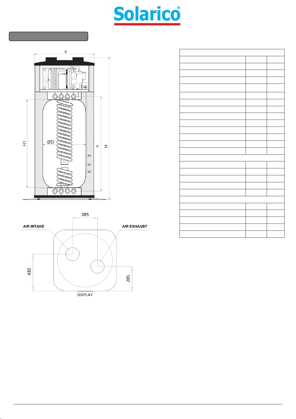
10 UNIT DIMENSIONS
All connections are 5/4"
Air duct connections have a diameter of 150mm. Connection pipes need to have the same diameter or bigger.
UNIQUBE HEAT PUMP
D (diameter)
(mm)
620
H1 (height)
(mm)
1300
h (connectors)
(mm)
1470
H (height)
(mm)
2000
a (width)
(mm)
734
max. working temp.
(oC)
90
max. working pressure
(bar)
6
max. test pressure
(bar)
9
Net tank capacity
(liters)
290
Approx. weight
(kg)
147
S2 Solar sensor position
(mm)
1110
S3 Heating sensor position
(mm)
910
S4 DHW sensor position
(mm)
710
Pivot measurement
(mm)
1730
Solar heat exchanger
dimension
5/4’’
max. working pressure
(bar)
10
max. test pressure
(bar)
15
capacity
(liters)
5
output area
(m2)
1,2
Water heat exchanger
dimension
5/4’’
max. working pressure
(bar)
10
max. test pressure
(bar)
15
capacity
(liters)
15
output area
(m2)
3,8
Left side

8
11 UNIT INSTALLATION
Minimal space requirements for installation and maintenance
The unit must always be installed in a vertical position. We recommend that the unit is inclined 2-3° backwards to
enable smoother condensate runoff.
WARNING!
After placing the unit in its final location, wait at least 1 hour before turning the unit on.
WARNING!
In case of service intervention and if minimum clearances are disregarded, the user covers the costs
incurred.
Min. one elbow is required. Because the inlet and outlet air connections are very close together, there is a possibility of
cold air recirculation, the device will go to defrost mode more often.
WARNING!
Good insulation of neighbouring walls is advisable.
Installation possibilities:
WARNING!
Maximal length of air ducts is 10m. Each bend 90°reduces the maximal length for 1 m. All air duct pipes need
to be insulated to prevent condensation. Never reduce the internal diameter of the pipe.
When the air inlet and outlet are in a
different space, each space needs to have
an opening to the outside or they need to
be connected with an opening surface at
least 300mm2 to be able to equalize
pressure.
9
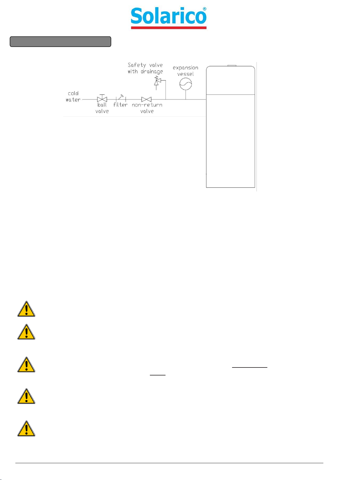
12 WATER CONNECTION
The cold water connection must be performed according to the scheme above. The maximum allowed pressure in the
hygienic domestic water system is 1,0 MPa, a safety valve sould be choosen by installer. Expansion vessel for the
hygienic domestic water circuit is optional, and is not mandatory necessary.
Hot water connection can be directly to tap, or can be upgraded with a circulation pump. Return from the circulation
system can be connected to the connection marked with “A”in scheme “10 Unit dimensions”.
During rapid water heating, a small water leakage on the safety valve can occur. This is not due to damage but due to
normal event of water expansion. This water needs to be captured and lead into drainage.
In case of a solar system or other heat source connected to the internal heat exchanger, it must be assured that the
pressure in the heat exchanger never exceeds 1,0 MPa. It must also be assured that the water does not exceed 80°C.
Damage to internal components or heat pump can occur.
In case that the additional heat exchanger is not to be used, it needs to be filled with glycol to prevent corrosion. It is
not allowed to close both sides of the heat exchanger to enable pressure equalization.
WARNING!
Improper installation of the unit can lead to damages or malfunction of the unit and loss of rights under
warranty.
WARNING!
Connect the unit to the system using removable pipe unions, so that the unit can be easily moved or removed
in case of a service intervention without the need of a greater intervention in the piping system.
WARNING!
When connecting the unit to the heating system it is necessary to prevent the formation of a galvanic couple
and related corrosion. To connect the unit to the heating system it is MANDATORY to use the enclosed
transition pieces, also the piping system MUST be electrically grounded. In case of failure due to improper
device connection the manufacturer will take no liability or warranty.
WARNING!
Before the unit is turned on, it needs to be filled with water and the system completely vented. To do this,
open all hot water taps and wait until water starts to flow from all of them.
WARNING!
On the back side of the unit there is a pipe connection for condensate drain. At high water usage and high air
humidity, more than a few litres of condensate water per day can occur, so this connection must be
connected to outlet drainage. This pipe needs to have a constant incline of at least 1° and must be always
clean.
5/4”
10
WARNING!
Condensate pipe must be checked and cleaned once per month.
DANGER!
The supply socket must be positioned at least 1,5m above ground level, to avoid direct water spray causing
injuries or damage. The socket must be earthed, secured with a 16A fuse and FI relay with max. current
0,03A. The wire cable to the socket needs to be at least 3x1,5 mm, only the heat pump can be connected to
the socket.
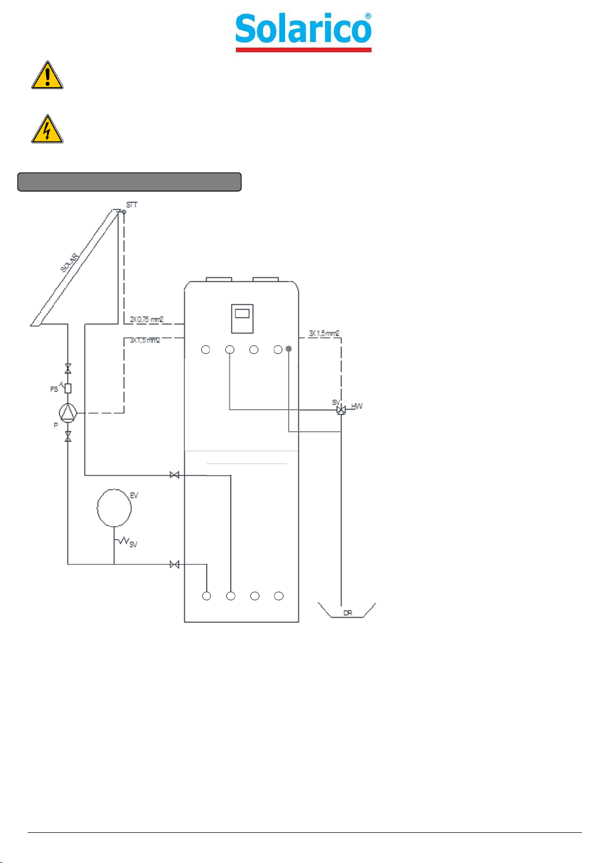
12.1Solar collector installation
Marks:
STT: solar temp. sensor
P: solar circulation pump
EV: solar expansion vessel
SV: safety pressure valve
FS: flow limiter with flow meter
SV: electronic safety valve
HW: hot water outlet
DR: drainage
The solar system must be connected to connections marked with »F« and »G«on scheme »10. Unit dimensions«.
The solar circulation pump must be connected to connection clamps marked with »Solar pump«. The enclosed
temperature sensor for the solar system must be connected to connection clamps marked with »Solar temp.«. The
installer needs to remove the resistor and then connect the enclosed temperature sensor for the solar system. On the
hot water outlet, it is advisable to install an electronic safety valve, which will open water when it is heated too much by
the solar system. This electronic safety valve needs to be connected to connection clamps, marked with »Solar drainage
valve«. All connection clamps can be found inside the heat pump, under the top plastic cover.
After installation and connection of the solar system, all parameters for the solar system need to be checked and
properly set. Parameter /01 has to be set to »2«, and parameter /02 to »3«. Other parameters are described in table
»parameters«.

11
When connecting other additional sources of heating, for example. a gas furnace or a biomass stove, follow the steps
above, but you must change the parameters N01 from 0 to 1, n11 from 0 to 1, N03 from 5 to 20 and N10 of 84 to 70. A
detailed explanation of the parameters is given in chapter PARAMETERS.
WARNING!
Failure to abide with the above instructions can lead to device malfunction or failure. In this case rights under
warranty are lost.

12
13 TRIAL OPERATION
13.1Confirmation before trial operation
1) All the installation preparations are complete.
2) Water heater is installed correctly.
3) The pipelines and wiring connections are correct.
4) The accessories are installed correctly.
5) The drainage is unblocked.
6) The thermal insulation is intact.
7) The earthing wire is connected correctly.
8) The power voltage is consistent with the rated voltage of the heater.
9) There is no obstacle at the air inlet and outlet of the unit.
10) All of the electric protection is working correctly.
11) The water tank is full.
CAUTION:
Before using this unit, please follow the steps below.
Adding water: If the unit is used for the first time or used again after emptying the tank, please make sure that the tank
is full of water before turning the power on.
NOTE
The ball valve at water inlet should be open when the unit is in operation.
WARNING!
Operation without water in the water tank may result in damage of freon heat exchanger. Due to such
damage, the supplier is not responsible for the quality issue.
DANGER!
Water over 50°C may cause serious burns or death. Special care should be paid to children, the disabled and
the elderly.
WARNING!
Failure to abide with the above instructions can lead to device malfunction or failure and serious material or
human damage. In this case rights under warranty are lost.

13
14 UNIT SETTINGS
When the unit is connected to the water system and filled with water, it can be connected to the power supply:
Power supply can only be plugged into a grounded socket (16A, 230V / 50 Hz).
14.1Operations
a) Keys
14
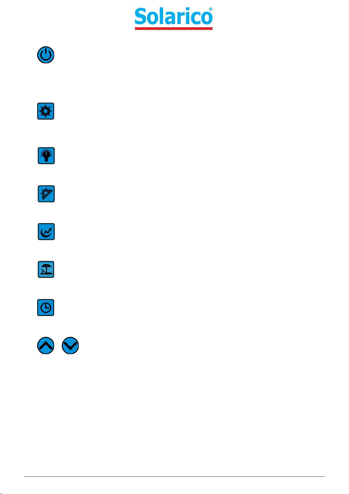
b) Key Introduction
ON/OFF
Tap this key to turn the unit ON/OFF. When the unit is on, the color of the key will turn to red.
Heating Modes
Heating mode
i. Tap this key to select normal heating mode, the color of this key will turn to red.
ii. Go to factory parameters setting function by pressing and holding this key for 10s.
Intelligent Mode
Tap this key to select intelligent heating mode, the color of this key will turn to red.
Eco Heating Mode
Tap this key to select ECO heating mode, the color of this key will turn to red.
High Require Mode
Tap this key to select the high require heating mode, the color of this key will turn to red.
Holiday Mode
Tap this key to set the holiday ON/OFF program, the color of this key will turn to red.
Clock
Set the timer and date.
/ UP/DOWN
Increase/decrease the setting value.
15
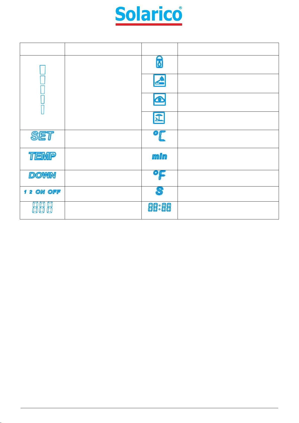
c) Status icons
Status icon
Meaning
Status icon
Meaning
The volume of hot water
available in the tank
Key-Lock
A WI-FI adapter is connected with the
unit.
The unit is connected to »cloud«.
The holiday function is active.
It is shown when parameter
is being set
Take centigrade as the unit
It is shown when
TOP/DOWN temp. is
displayed
Take minutes as the unit
It is shown when DOWN
temp. is displayed
Take fahrenheit as the unit
It is shown when timer/clock
is being set.
Take seconds as the unit
This area will show temp
value or parameter value.
This area will show down temp. or
clock time
16
15 OPERATION INSTRUCTIONS
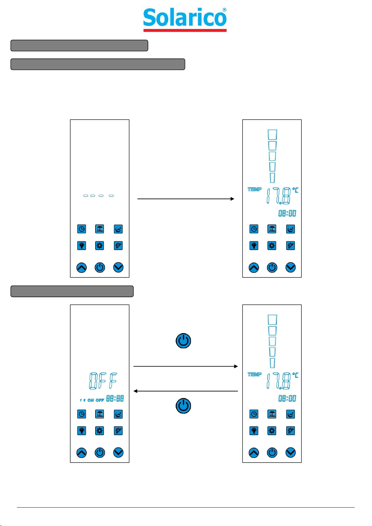
15.1Preparation before running the unit
1) The controller will keep loading the parameter for 15s.
2) Ensure that the water tank is filled up with water.
3) If there is no operation for 1min, then keyboard will go dark. You can tap any key to light it up.
15.2Unit ON/OFF operation
Wait for 15s
Tap and hold for 2s to turn
on the unit
Tap and hold for 2s to turn
off the unit
Table of contents
Popular Heat Pump manuals by other brands

ClimateMaster
ClimateMaster Tranquility Technical guide

Mitsubishi
Mitsubishi PUHZ-W85VHA2.UK Service manual

Midea
Midea RSJ-15 Installation and owner's manual

Steinbach
Steinbach Waterpower 8500 Quick instruction guide

Daikin
Daikin EKHH2E-AV3 Installation and user manual

Weltem
Weltem AMEARICOOL WPH-3000 owner's manual


CTC Union
CTC Union EcoHeat 5 Installation and Maintenance

Daikin
Daikin 4MXS100EV2C Service manual

Allied Air
Allied Air 4SHP13 series installation instructions

Carrier
Carrier 30RQ 039 Series Installation, operation and maintenance instructions

Carrier
Carrier 38MARB Installation instruction

LG
LG THERMA V HN1639 owner's manual