PUHZ-W85VHA2R1.UK PUHZ-W85VHA2R1-BS.UK
PUHZ-W85VHA2R3.UK PUHZ-W85VHA2R3-BS.UK
noitidnocgnitarepolanimoN)ycneuqerF,egatloV,esahP(ylppusrewoP
Nominal water flow rate (Heating mode) L/min Heating(A7/W35)
Heating 7°C+)blub-yrD(erutarepmetriaedistuOWkyticapaC
(A7/W35) 6°C+)blub-teW(erutarepmetriaedistuOPOC
5°C3+/03+)teltuo/telni(erutarepmetretaWWktupnirewoP
Heating WkyticapaC Heating(A2/W35)
(A2/W35) 2°C+)blub-yrD(erutarepmetriaedistuOPOC
1°C+)blub-teW(erutarepmetriaedistuOWktupnirewoP
Pressure difference (water circuit) )teltuo/telni(erutarepmetretaWaPk -/+35°C
Heating pump input (based on EN14511) kW Cooling(A35/W7)
5°C3+)blub-yrD(erutarepmetriaedis
tuOnim/L)edomgnilooC(etarwolfretawlanimoN
Cooling 4°C
2+)blub-teW(erutarepmetriaedistuOWkyticapaC
(A35/W7) EER
(COP)
Water temperature (inlet/outlet) +12/+7°C
Power input kW Cooling(A35/W18)
Cooling 5°C3+)blub-yrD(erutarepmetriaedistuOWkyticapaC
(A35/W18) EER
(COP)
Outside air temperature (Wet-bulb) + 24°C
8°C1+/32+)teltuo/telni(erutarepmetretaWWktupnirewoP
Pressure difference (water circuit) kPa
Cooling pump input (based on EN14511) kW
Note: "Capacity", "COP" and "Power input" in the above table are values that contains the "pump input (based on EN 14511) ".
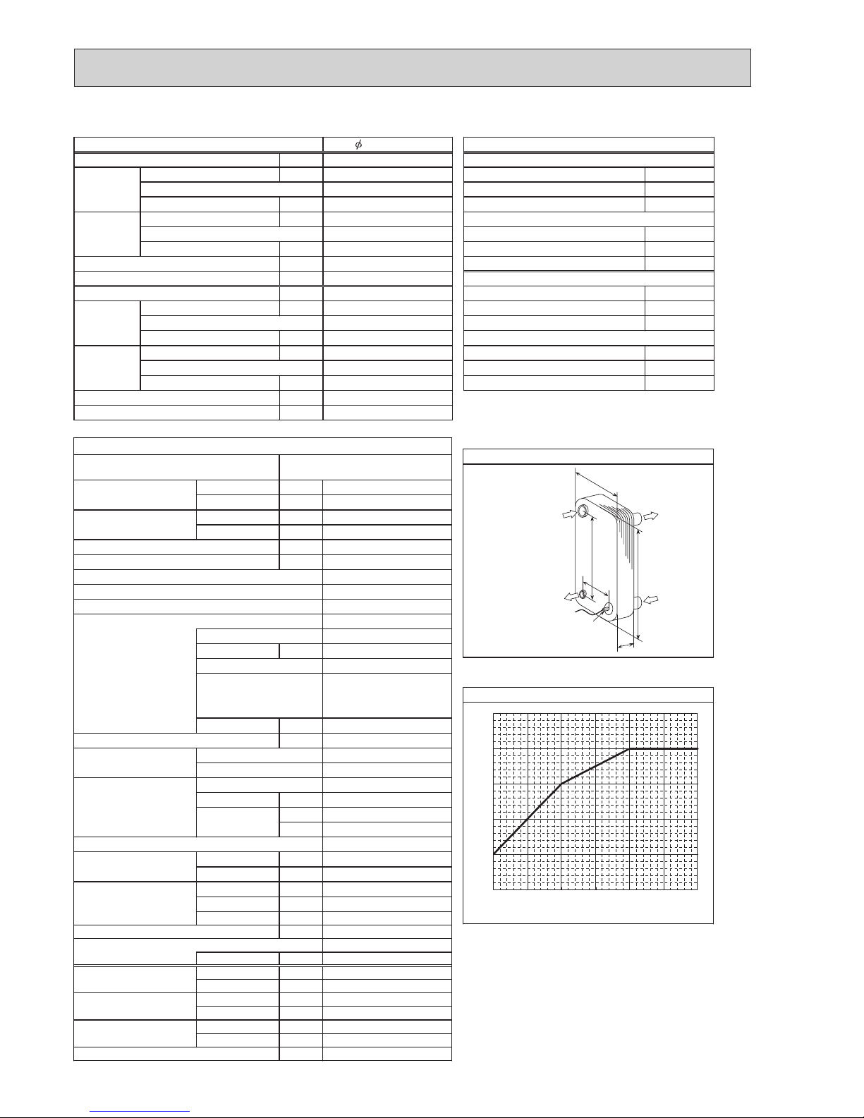
regnahcxetaehetalPsnoitacificepstinuroodtuO
Service Ref. MITSUBISHI
Running current Heating
(A7/W35)
MWA1–44LM
A
Cooling
(A35/W7)
A
Power factor Heating
(A7/W35)
39 mm:A
%
Cooling
(A35/W7)
mm2.862:B
%
Atnerruc.xaM mm39:W
AezisrekaerB mm523:H
gnisacretuO 77.1 mm:D
hsiniflanretxE setalp44
lortnoctnare
girfeR
Compressor
Model
Motor output kW
Start type
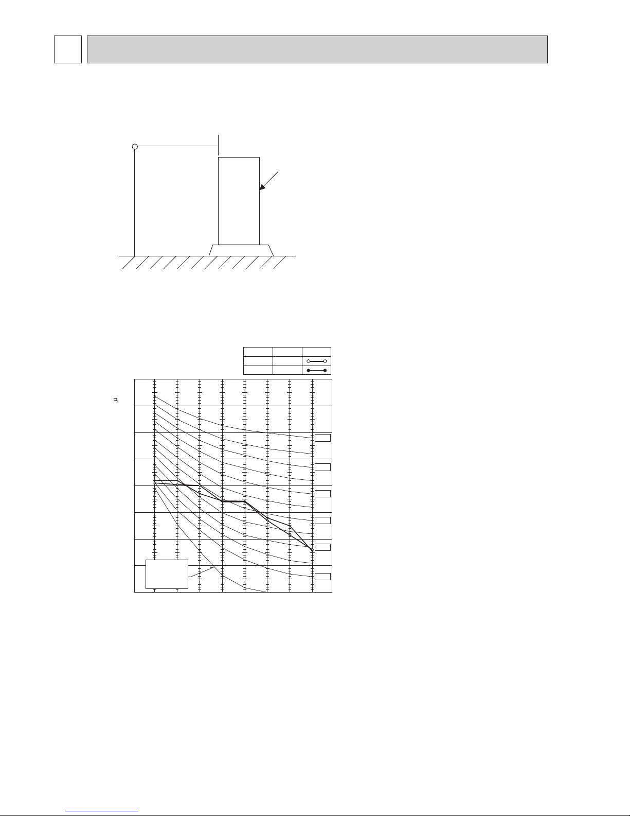
Protection devices Maximum outlet water temperature
Oil (Model) L
WretaehesacknarC
Heat exchanger Air
Water
Fan Fan(drive)×No.
Fan motor output
kW
Air flow m³/min
(CFM)
Defrost method
Noise level Heating dB
Cooling dB
Dimensions Width mm (in)
Depth mm (in)
Height mm (in)
)bl(gkthgieW
Refrigerant
*1 Hot gas with 4-way valve
Quantity kg (lb)
*2 At distance of 1m from outdoor unit
Guaranteed operating Heating °C
°C
°C
°C
°C
°C
*3 Grille
range (Outdoor) Cooling
Outlet water temp. Heating
(Max in heating, Min in cooling)
Cooling
Nominal return water Heating
temperature range Cooling
nim/LegnaretarwolfretaW
*4 With the optional air outlet guide, the operation at
−15°C outdoor temperature is possible.
48 *2
0.67 (FV50S)
943 (37-1/8)
R410A
(1,730)
Reverse cycle *1
Propeller fan × 1
0.060
10.0 to +25.8
2.4 (5.3)
−20 to +35
−5 to +46
(*4)
*5
+5 to +59
+8 to +28
+60
+5
(Min. 2.60) 8.50
0.02
2.68
13.5
21.5
7.50
7.50
3.93
9.38
Galvanized plate
0.012
Hermetic twin rotary
13.15
PUHZ-W85VHA2R1(-BS).UK
PUHZ-W85VHA2R3(-BS).UK
25.8
79 (174)
950 (37-3/8)
330 +30*3 (13+1-3/16)
23.0
HP switch
Discharge thermo
Comp. surface thermo
overcurrent detection
48 *2
-
1.3
1, 230 V, 50 Hz
25
2.47
1.91
(Min. 2.70) 9.00
4.18
3.04
10
2.15
3.17
TNB220FLHM1T
98
98
Linear expansion valve
Munsell 3Y 7.8/1.1
49
Plate fin coil
Plate heat exchanger
Inverter
W
H
D
Water OUT
Water IN
Ref. IN
(Heating)
Ref. OUT
(Heating)
Thermistor
(
TH
32)
A
B
40
45
50
55
60
65
−15 −10 −5 0 5 10
Ambient temperature [
°C
]
Maximum outlet water temperature [
°C
]
(SPL)
*5 For details of the min. return water temperature at
each water flow rate, refer to “3-2. AVAILABLE RANGE
(WATER FLOW RATE, RETURN WATER TEMP.)”.3-2. AVAILABLE RANGE
(WATER FLOW RATE, RETURN WATER TEMP.)”.
Note: We confirm that our units are tested based on EN14511.
−20