Solaris SunPump MACHRW010W Service manual

DC INVERTER
AIR TO WATER HEAT PUMP
INSTALLATION & INSTRUCTION
MANUAL
SunSun tm
PumpPump


1.1 In order to use this product better and safer, please read this instruction
carefully before install and operate it. Please pay attention to all the notice in
operation and maintenance. Save all manuals and documentation for future
reference.
1.2 Air to water pump is a special appliance. Improper installation will cause
damage and danger. It should be installed and maintained by the professionals.
Please contact our authorized local service point for installation and maintenance.
Please read and follow this instruction carefully before and during installation.
Remarks:
We will not bear the responsibility for any personal injury or unit damage caused
by non-Compliance of the regulations and instruction in this manual.
1.3 Please check whether the distribution power capacity, switch and socket
are compliance with the requirements of our unit power. Details please refer
to the rating label or parameter table in this manual.
1.4 The power should be equipped with leakage protection separately.
Power cable should be chosen in accordance with the operation
requirements of the unit.
1.5 The unit must be grounded safely. Do not use the unit if grounded unsafely.
Do not connect the ground line to the neutral and or tap water pipe.
1.6 The wire must be joined in compliance with the requirements of the wiring chart.
Do not alternate and or repair the unit personally.
1.7 Do not install the unit closed to inflammable, explosive and naked light spot.
1.8 To ensure the unit operate properly, please equipped with a filter in the water
input when installation.
Notice

1
2
2
3
4
4
4
7
7
8
8
9
10
10
10
11
13
15
15
16
17
18
18
18
19
21
21
24
24
25
I.Specification...............................................................
1. Model nomenclature.....................................................
2. Parameters of air to water heat pump..................................
3. Product appearance and installation dimension.................
II.Installation...................................................................
1. Unit installation position.................................................
...............
. .....................................
4. Pipe connection............................................................
5. Installation of the temp detector............................................
6. Selection of Electrical Wire............................................
7. Trial operation............................................................
III.Use...................................................................
1. .................................
2. ..............
3.
Parameters setting.......................................................
IV.Installation sketch......................................................
1. Hot water side water system installation drawing ...............
2. Air condition/floor heating water system installation drawing ...
3.
..................................................
V.Maintenance and repair................................................
1. Note
2. Malfunction indicating table............................................
3. ........
VI.Wiring diagram..................................................................
1.. Indoor Unit wiring diagram...................................................
2. Out door Unit wiring diagram............................................... .
3. ......................
4. Three way valve wiring diagram............................................
....................
...............
.........
.........
.................
............
.....
..........
..............
.....
.............
................
.............................
............
The user interface and function shows as below. .........
Use of wire controller.................................................................
4. ..............
...................
........
Air condition/floor heating and hot water side water system
installation drawing .................
..................
...........................................................................................
...........
Judgement and solution of malfunctions ...........................
...........
....
.....
......
2. The refrigerant piping connection for split type unit
3 Installation of terminal equipment
Between outdoor unit and indoor unit connection
Wire controller device installation
CONTENTS

The figure represents the horse power of unit
eg:010 means 1 horse power
A: Horizontal fan direction
B: Upward fan direction
Design alternative serial number
MA FP *** A (**)
Energy exchange medium
MA: Refrigerant
MW: Water
FP: Fan coil
Outdoor unit model nomenclature
1. Model Nomenclature
MA CHR W S *** WA / PS(B 01 D)
Source medium
MA: Airsource
MW: Ground source
Function of the unit
C: Aircooling
R: Airheating
CH: Air cooling and hot water
CR: Air cooling and heating
CHR: Air (heating+cooling) and hot water
Energy exchange medium
A: Refrigerant
W: Water
Z: Integrated type
W: Split type(indoor unit )
A: Horizontal fan direction
B: Upward fan direction
(Omit the split type unit model)
B: DC Inverter
E: EVI
(Without inverter or EVI omitted)
The figure represents the horse power of unit
eg:010 means 1 horse power
P:With built in pump
(Without built in pump omitted)
S:3phase (single phase omitted)
S:with solar(Without solar omitted)
D:With electrical heating
(Without electrical heating omitted)
01:One plate heat exchanger
02:Two plate heat exchangers
Indoor unit model nomenclature
1

2.Parameters of air to water heat pump
Note:(1)Cooling:Outdoor air temp:DB 35 /WB 24 ,Outlet water temp:7 ,Inlet water temp:12 ;
(2) Outdoor ambient temp:DB 20 /WB 15 ,water tank water temp from 15 to 55
(3) Outdoor ambient temp:DB 7 /WB 6 ,water outlet temp:45 ,water inlet temp:40
(4)Using in ambient temperature:-15 43 .
INDOOR UNIT
Rated Cooling Capacity
Rated Input Power(Cooling)
Rated Input Current(Cooling)
COP
Rated Input Power(Heating)
Rated Input Current(Heating)
COP
Rated Input Power(Heating)
Rated Input Current(Heating)
Auxiliary electric heater Power (Optional)
Auxiliary electric heater Current
Maximum input Current
Power Supply
Compressor
Compressor Qty
Noise
Water outlet/water inlet
Water Flow Volume
Refrigerant Gas Type
Indoor unit Net Dimensions(L/M/H
Indoor unit Shipping Dimensions L/M/H
Outdoor unit Net Dimensions(L/M/H
Outdoor unit Shipping Dimensions L/M/H
Indoor unit Net Weight
Indoor unit Shipping Weight
Outdoor unit Net Weight
Outdoor unit Shipping Weight
MACHRW
kW
BTU/h
kW
A
kW
BTU/h
kW
A
kW
BTU/h
kW
A
KW
A
A
V/PH/Hz
dB(A)
inch
m /h
mm
mm
mm
mm
kg
kg
kg
kg
030W/(B01)
7.5
25600
2.34
10.7
10.5
35800
4.15
2.53
11.5
8.3
28400
3.6
2.29
10.4
7.5
36
17.3
1
48
1
1.81
600/440/740
650/500/780
830/380/710
880/430/810
60
70
35
40
208 230V/1PH/60Hz
DC Inverter
R410A
Rated Heating Capacity
3
030W/(B01)
2.5
8600
0.78
3.6
3.5
12000
4.15
0.85
3.8
2.8
9600
3.6
0.76
3.5
/
/
5.8
1
46
1
0.62
600/440/740
650/500/780
830/380/710
880/430/810
45
53
35
40
030W/(B01)
5.0
19200
1.56
7.25
7.0
23900
4.15
1.69
7.6
5.6
9600
3.6
1.52
7.0
7.5
36
11.6
1
47
1
1.21
600/440/740
650/500/780
830/380/710
880/430/810
50
58
35
40
2

3
3. Product appearance and installation dimension
3.1Dimension of indoor unit
3.2 Dimension of outdoor unit
A
B
C
D
Size
Units: mm
MODEL
390
405
106
500
A
B
575
415
A
B
Size
Units: mm
MODEL
MAFP060A
A
B
615
395
MAFP020A
A
B
Size
Units: mm
MODEL
MACHRW010W/(B01)
MACHRW020W/(B01D)
MACHRW030W/(B01D)
C
D
A
B
615
395
MAFP040A
A
B
Size
Units: mm
MODEL

4
Notice:
1.To get enough air for ventilation of the unit, the installation position should be with good ventilation.
2.The installation position can hold the outdoor unit without noise and shake.
3.No sunlight to the unit. Set an awning if necessary.
4.The water from rain and defrosting can be discharged in the installation position.
5.The unit will not be covered by snow in the installation position.
6.The discharged air will not face strong air in the installation position.
7.Assure the noise caused by the unit ventilation and operation will not affect the neighbor.
8.The installation position will not be affected by garbage, oil and mist.
9.The outdoor unit will be damaged under the condition with oil(engine oil), salt(sea area) and
sulfide air(near thermal spring and refining factory).
Adapter connector
Needle valve
valve plug
valve plug nut
Needle valve nut
Adapter connector nut
Indoor unit and outdoor unit
copper connecting pipe
Stop Valves
2. The refrigerant piping connection for split type unit
2.1 Each component's names and function of refrigerant stop valve
Adapter connector
Needle valve
Valve plug
The connecting pipe joint of indoor unit and
outdoor unit .
To discharge the air in the connecting pipe
and outdoor unit by refrigerant pressure or
connect a vacuum pump.
Turn on or turn off the stop valves.
II. Installation
1. unit installation position
The pretty high condensation temperature (cooling) and pretty low evaporation temperature
(heating) will affect the operation of outdoor unit. To achieve maximum efficiency, please select
the installation position under below regulations:
To avoid ventilation short, the outdoor unit discharged air should not return when installation.
Please keep enough space around the outdoor unit for repair. Right and wrong means as below:
Wrong Right

5
As the following steps:
F: After the air discharging, open the stop valve at the indoor unit low pressure side.
G: Screw and close the screw cap on the stop valve.
E: Close the needle valve after open it about 10-20 seconds ,The time is according to the size of
outdoor unit and the length of the connecting pipe.
D: Open the needle valve by small screwdriver , and this outlet will discharge the air in connecting
pipe and outdoor unit at the same time.
C: Open the stop valve at indoor unit's high pressure side by valve plug,
Note: don't open the one at low pressure side.
B: Open the stop valve at outdoor unit high/low pressure side by valve plug.
A: Unscrew the valve plug nut on the stop valve , and unscrew the needle nut on the indoor unit low
pressure side.
NOTE : The direction of the arrow is the air discharging flow direction which is same as the refrigerant flow direction.
NOTE : The air is discharged from this outlet.
1
2
Needle valve
valve plug
valve plug nut
Low pressure
side
Needle valve
valve plug
High pressure
side
Indoor unit Outdoor unit
Needle valve
valve plug
valve plug nut
Low pressure
side
Needle valve
valve plug
High pressure
side
Big pipe
Small pipe
2
1
As the picture show
2.2 The unit refrigerant pipe connecting
A: According to the indoor and outdoor unit fixed
location and location of holes through the wall,
choose a good direction lead to pipe. Then begin
the indoor pipe connection work.
B: Use a wrench to remove the adapter
connector nut;
High pressure valve
Low pressure valve
Copper pipe
Copper pipe
Connecting pipe
Adapter
connector
Flare nut
C: As shown on the right, press the trumpet on the
connector cone, then hold the connection pipe
with one hand, so that keep the connector axis
in the first line, the other hand the gradually
screw the flare nut on the connector, then
tighten with wrench.
2.3 Air discharge (by indoor unit refrigerant)
If the system is small, use refrigerant empty way to discharge the pipe and outdoor unit air, to discharge the
air in the connecting pipe and outdoor unit, when there's refrigerant in the pipes originally, just open the
low pressure side needle valve of indoor unit to discharge the air by refrigerant pressure.

6
E: After the air discharging(vacuumming),disconnect
the connecting between the pressure gauge and
indoor unit stop valve .
F: Open the stop valve at indoor unit high/low pressure
side by valve plug, then let the indoor unit's refrigerant
flow in outdoor unit(if need to add more refrigerant, please refer to 2.4).
When the pipe is too long, please add
additional refrigerant as following formula:
Additional refrigerant amount=
(one-way tube length -5)m x (0.015~0.02) kg,
choose 0.015 or 0.02 according to the size
of diameter.
When the tracheal diameter = 12.7,
choose 0.015;
when the diameter = 15.88, choose 0.02 .
The methods to add refrigerant
refer to the right diagram :
2.5 Add refrigerant
Stop valve
High pressure
side
Hose
Composite table
Outdoor unit
Indoor unit
Low pressure side
Stop valve
Scale
Refrigerant
charge tank
After discharge the air, use electronic leak detector or soapy water to test all the connectors in the
indoor and outdoor unit.
2.6 Leak check
As the picture show, connect the vacuum pump
with the pressure gauge, and then connect the
vacuumed connecting pipe with the needle valve
on the indoor unit low pressure side.
B: Unscrew the valve plug nut on the stop valve ,
and unscrew the needle nut on the indoor unit
low pressure side.
C: Open the stop valve at outdoor unit high/low
pressure side by valve plug.
Note: Do not open the indoor unit high/low
pressure side stop valve.
D: Open the compound pressure gauge and vacuum
pump to vacuum the so that
the absolute pressure not higher than 130Pa, and
keep the pressure does not rise within 5 minutes
after vacuum.
As the following steps:
A:
outdoor unit and pipe,
2.4 Air discharge (by vacuum pump)
Stop valve
Vacuum pump
High pressure side
Hose
Composite table
Outdoor unit
Indoor unit
Low pressure side
Stop valve
If the system large or after maintenance of outdoor system, should use the vacuum pump discharge way
to empty the air and water within the system.

7
4.7.The unit air-conditioning side and the hot water side which connect to running water must be
installed a one-way valve, filter and pressure relief devices (pressure relief devices used on
the closed water tank, water tank accessories in general, the parameter value 0.7MPa), in
accordance with the flow and valve arrow direction, to avoid flow be obstructed.
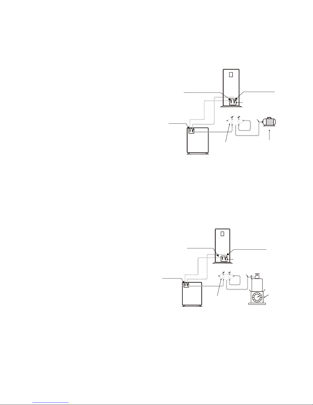
4.8.The unit hot water side circle outlet connect to tank circle inlet, and the host hot water side
circle inlet connect to tank circle outlet,tank hot water supply connect to hot water pipe.
4.9.Air-conditioning side buffer tank in series installed on the outlet of the main pipe.
4.10. After hot water side and air-conditioning side water system pipes, circulated pipes, hot water
supply pipes connected, it must be pipe connection rigorous testing , plus 0.7Mpa pressure
testing 24 hours, system pipes connector no leakage and clean and sewage pipes, to ensure
that the system clean, no debris. No leakage after the test, then pack the pipe and valve with
insulation (including the replenishment pipes and valves).
4.11.In order to discharge the water system air clean, avoid air trapping in the pipeline, the water
supply return pipe highest point should be set up a automatically exhaust valve.
4.12.The water system expansion tank, automatic water valve and stop valve should be installed
indoors, to prevent water pipes and valves crack when not use in the winter.
4.13.The metal pipe must be used above 50mm thickness of glass fiber or high-density fire
retardant PE for thermal insulation and moisture, PPR water pipe can be used 30mm
thickness of glass fiber or high-density fire retardant PE for thermal insulation and moisture to
prevent cold, heat loss and condensation.
4.14.The unit water inlet and outlet must install a thermometer, water pressure gage, to facilitate
inspection when operate.
3. Installation of terminal equipment
3.1.Indoor terminal equipment installation (such as: fan coil, radiator heater or floor heating), the
equipment should be installed in accordance with relevant regulatory requirements.
3.2.In accordance with the requirements of engineering design drawings, installation and
construction.
3.3.Use a soft connector to connect the unit and fan coil inlet and outlet pipes; install fan coil
condensate drain pipe, connect the condensate drain interface, and to ensure smooth drainage
of condensate water.
4. Pipe connection
4.1.Pipe material selection, can be stainless steel pipe, copper pipe, aluminum water pipe, hot
water PPR pipes and so on, according with national health and safety standards, heat-
resistant, rust-proof, no scaling pipe.
4.2.The choice of pipe sizes can be used the one which is matches the heat pump inlet and outlet
main pipe, and, respectively connect to heat pump inlet and outlet, and follow the proper
construction of plumbing standards.
4.3.Water tank outlet pipe and overflow pipe installed in the gutter or outlet position as far as
possible, where convenient to drainage.
4.4.The unit and the junction to the tank must be installed valve or demolition loose joint, for
maintenance use.
4.5.Water pipes are arranged reasonably to minimize bending and reduce the pressure loss of
water system
4.6.The unit air-conditioning side and the hot water side circle inlet must be installed a above 50
mesh water filter to reduce the water system resistance loss.

5.1.The first step Daub the heat conduction silica gel spreads in the front of sensor, and insert
into the detector.
5.2.The second step use < 5 pin to push the detector into the end of the detector against the
end of the sensor, and marks on level of the pin and the detector.
5.3.The third step putout the pin the position of mark to be at the same level with the inlet of
detector check whether the sensor is inserted to the pipe terminal.
5.4.The fourth step the inlet of the detector is sealed with the glass silica gel, and keep the inlet
of the detector upwards and uprightness about an hour
6. Selection of Electrical Wire
6.1 Voltage drop may occur due to the large current draw during compressor starting, and may be result in the
compressor is difficult to stat. So we recommend selecting the wire specification from the table below.
6.2 Specification Table of Electrical Wire
Mode:MACHRW
010W/(B01)
020W/(B01)
030W/(B01)
Wire Specification Circuit breaker Voltage
2
2.5mm 10AMP
2
2.5mm
2
2.5mm
14AMP
20AMP
208~230V/1PH/50Hz
8
The head
of sensor
The heat
conduction
silica gel
The first step The second step The third step The fourth step
The heat
conduction
silica gel
The head
of sensor
< 5 pin
< 5 pin
The heat
conduction
silica gel
< 5 pin
Detector
Tank Tank Tank Tank
Detector
The head
of sensor
Detector Detector
The head
of sensor
Note:
1) Tubing pipeline should be separate test pressure, must not test with hot water unit or tanks.
2) The
3) The .
4) Water can drain from the pressure relief device drainage pipe, and the piope keep open to
atmosphere.
5) The pressure relief device regularly move to remove the calcium carbonate, and prove that
the device is not plugged.
6) Installation of one-way valves, filters and pressure relief device, valve body arrow as same
as flow direction .
7) The pressure relief device discharge pipe should be installed in the frost-free environment in
A continuous down way.
Water system allows working pressure range: 0.2-0.7 MPa.
Water system allows working temperature range: 5-60
5. Installation of the temp detector
208~230V/1PH/50Hz
208~230V/1PH/50Hz

7. Trial operation(should be operated by professionals)
7.1 Check before trial operation
7.1aCheck the pipe system. Check the whole pipe system. Ensure the water volume in the system
is full and the air is exhausted completely. Check whether the valve is open throughout the
system and the thermal insulating of the pipe is well.
7.1b Check the power supply and distribution system. Check whether the power supply voltage is
normal, the power distribution accessory screws all tighten, supply power is in compliance
with the wiring diagram and the wire is grounded well.
7.1c Check the air cooled water chiller. Check whether any screw loose. Check the signal indicator
light(green) of the outdoor unit control panel is illuminated normally and the fault indicating
lamp(red) is illuminated. Connect the pressure gauge to the freon feed mouth for checking the
pressure during operation. Disconnect them after test is ok.
7.2 Trial operation
7.2a Press on/off in the remote controller, the water pump and fan start immediately.
The compressor start after the unit operates for some time. Observe and determine if there s
any abnormal sound during operation. Stop to check the unit if there s abnormal sound. The
unit can continue to run only when there s no abnormal sound. Check whether the cooling
system pressure is normal at the same time.
7.2b Check whether the input power and current of the unit are compliance with the parameter in
this Instruction. If not, stop to check the unit.
7.2c Observe whether the outlet water temperature is normal.
7.2d Parameter of the remote controller has been set before leave of the factory. Never alternate
them personally.
9
6.3 Caution ofGround The internal motorprotector does not protectthe compressor against all
possible conditions Please be surethat the system utilizesthe ground connection when installed
in the field.
6.4 Warning: To avoid fire, electric shock and other accidents, keep in mind about these tips:
A: Only use power supply voltage indicated on the label, if you do not know the family of voltage,
contact the dealer or local power company.
B: When you use the unit by the maximum current please view the specifications, so make sure
our home's power supply (current, voltage and cable) to meet the machine's normal load
requirements.
C: To protect the power lines. Power lines should be fixed, so that people will not be trip over or
the lines damaged by other things. Paying particular attention to plugs, which should be easily
plug into the socket, careful the plug position.
D: Do not overload wall plugs or extension the cable. Line overload can cause fire or electric shock.
E: To ensure your safety, you must plug the power lines into the socket with a grounded three-phase,
and check to ensure your socket is accurate and reliable grounding.

10
Timer and clock setting button
1. Wire controller device installation
The remote controller is designed and employed standard electrical box dimensions(86*86,
fixed hole distance 60mm). The electrical box and three core can be built in the wall before
decoration, which makes the interior decoration more perfect. The illustration shows as below:
Unit turn on/off button
Note : This icon is to show whether it is underhot water tank
mode or aircondition mode. When this icon appears,it shows
that the unitis running air condition mode.
Note : In standby mode, thistemperature meaning the ambient
temperature. In hotwater tank mode, this temperature meaning
hot water tanktemperature. In air condition mode, thistemperature
meaning water inlettemperature.
Note :In standby state, it will not show here. In the hotwater tank
mode, it ishot water tank temperature. In airconditioning mode,
it is inletwater temperature.
Note :When manually open auxiliary electricalheating, the icon
will flash.
1
2
3
III. USE
ABC
E
F
D
G
H
I
KJLN
O
M
S
R
Q
P
T
MM
Auxiliary electrical heating icon
4
3
2.The user interface and function shows as below.
Cover the face covering in the reverse procedures
as shown in Illustration 2 and Illustration 1 to
complete the mounting of the remote controller.
Put the remote controller in the electrician base .
box and tighten the two setscrews.
Illustration 3
Illustration 1
Illustration 2
Use flat screwdriver to press down the two back-off
and lift open the face covering.
Remove the top covering leftwards to disengage
two top back-off.
Illustration 4
Cooling mode icon
Heating mode icon
Hot water tank mode icon
Defrost icon
Air condition mode icon
The actual temperature
Celsius units
Timer on icon
Timer off icon
Down setting button
Up setting button
Model select setting button
Time display area
Button lock icon
The setting temperature
Temperature icon
Setting icon 4
Turn on / off button

11
MMMMMMMMMM
MM
MM
MM
Hot water mode
Under the running status, press the button change the running mode.
Heating mode
Cooling mode
Hot water +
Heating mode
3.2 Model select operation
Picture 1
3. Use of wire controller
3.2 Turn on/turn off the unit
Under standby status ,press the button turn on the unit, the operation mode icon display on the
wire controller. the unit is running operation mode. Show as the picture 1 .press the button again ,
turn off the unit. Show as the picture 2.
Picture 2
Hot water +
Cooling mode
Hot water mode, the temperature on the left side of the wire controller is the set
temperature of hot water tank, and on the right side is the actual temperature of
the hot water tank.
Air condition mode(including heating mode and cooling mode ), the temperature on
the left side of the wire controller is the set temperature of water inlet(heating or cooling),
and on the right side is the actual temperature of water inlet.
Hot water mode & Air condition mode, the unit default priority hot water mode,
So the unit running hot water mode at first, the temperature on the left side of the
wire controller is the set temperature of hot water tank, and on the right side is
the actual temperature of the hot water tank. When the hot water tank temperature
reaches set temperature, the unit will running air condition mode automatic. This
moment the temperature on the left side of the wire controller is the set temperature
of water inlet(heating or cooling), and on the right side is the actual temperature of
the water inlet.
MM
MMMM
3.1 Keyboard locking / unlocking operation
Without operation for the controller in 30 seconds, The icon will display on wire controller. It mean
that keyboard are lock. And press button for 3 second. Keyboard are unlock.
3.3 Modify the set temperature
Under the hot water mode, press button and button, can modify the set temperature of hot water.
Under the air condition mode, press button and button, can modify the set temperature of water
inlet.

12
Press button until wire controller appear icon. Two seconds later, the display temperature on
the wire controller will change(refer to picture 2 and picture 3). Now you can press button and
button modify the set temperature of water inlet under the cooling mode. After modification, press
button to revert to the former mode.
MM
Picture 1 Picture 2 Picture 3 Picture 4 Picture 5
For example, wire controller display hot water mode & cooling mode. The unit is running hot water
mode, but I want to modify the set temperature of water inlet under the cooling mode. Now I will be
following
3.4 Clock setting
Press the button for 3 seconds, the place of minute keeps flicking, press button to
adjust the setting of minute. Then press button and the place of hour will keep flicking . Press
the button to adjust the setting of hour. Press button again to complete and exit the time
setting mode.
Press button , the minute , you can press button to
adjust the setting of minute.
ou can press button to adjust
the setting of minute.
symbol flickers and the display flickers
Press again, the hour display flickers. Press the button to adjust
the setting of the hour. Press button again to complete the timming boot setting, and enter the timming
shutdown setting, by this time, the hour and the symbol flickers. Y
Press again, the hour display flickers. Press the button to adjust the
setting of the hour. Finally, press button to exit the timer ON/OFF setting. The following example shows
the heat pump set to turn on at 8:30 every morning, and turn off at 23:30 every night .
3.5 Unit turn on /turn off timer setting
MM
MMMMMMMM
MMMMMMMM
MM
Under the hot water & air condition mode, press button and button, can modify the set temperature
of the current operation mode. If the unit is running hot water mode, and you want to modify the set
temperature of water inlet(heating or cooling), you can follow the steps below.
MMMMMM
Press
button
Press
to adjust
the setting
of the minute
Press ,then
press
to adjust
the setting
of the hour
Press ,complete
the timming boot
setting, and enter
the timming
shutdown setting
Press
to adjust
the setting
of the minute
Press ,then
press
to adjust
the setting
of the hour
Press
button

13
NOTE : Every time manually turned on or turn off, it will clear all timer settings.
1
Only set
unit timer on.
Only set
unit timer off.
3.8. Checking of state parameter
Press and button at the same time to enter the state parameter interface. Then, press
or button to check the state parameters.
Meaning
DC inverter compressor frequence
Current
Water inlet temperature
Water tank temperature
Water outlet temperature
Indoor ambient temperature
Display
d01
d02
d03
d04
d05
d06
Meaning
Discharge temperature
Outdoor a temperature
Coil temperature
Suction temperature
Cooling coil temperature
Electronic expansion valves efficiency
mbient
Display
d07
d08
d09
d10
d11
d12
These settings are for Engineers only, please call if you require to change any of the system parameters.
Press and button at the same time to enter the system parameter setting interface.. Press
or to view P1-P19 parameter. Press button again to set value you need. Parameter setting
as below:
4. Parameters Setting
Number
Means Range
Default
20 ~55
15 ~45
5 ~35
1 ~10
0/1
20 ~55
2~90min
1 ~10
55
0/1
0
45
30min
The water tank temperature setting of hot water tank mode
The water inlet temperature setting of heating mode
The water inlet temperature setting of cooling mode
Hot water tank mode, water tank temperature difference between the
unit stop heating and restart heating
The control mode of defrost
0:automatic 1:manual
The limit of heating mode set temperature
Heating mode, water inlet temperature difference between the unit stop
heating and restart heating
The auxiliary electric heater start delay time(the time to
delay after compressor turn on
The optional of auxiliary electric heater
0:heating mode electric heater 1:without electric heater 0/1
The setting temp. and real temp. difference began to keep constant temp. 0~6
2
Water tank electric heater stared temperature 30 ~55
50
The ambient temperature setting of ambient temperature too low protection -25 ~-1
-15
40
12
5
5
P1
P2
P3
P4
P5
P6
P7
P8
P9
P10
P11
P12

14
P13
P14
P15
P16
P17
P18
P19
P20
-20 ~10
5 ~45
25min~70min
-5 ~5
3 ~15
-7
0
13
45min
10
The maximum time of defrost status
Enter the defrost status setting of coil temperature
The compensation of hot water tank temperature
Exit the defrost status setting of coil temperature
Heating defrost cycle setting
The difference setting of solar cycle pump start working
The compensation of water inlet and outlet temperature
-5 ~5
0
2min~20min
8min
Model: 0:Hotwater/1:Heat/2:Hotwater&Heat/3:Cool/4:Heat&Cool/
5:Hotwater&Cool/6:Multifunction
Number
Means Range
Default
Note: If the unit is with electric heater, this parameter is 1, otherwise is 0.
60~6

Cold water inlet
4
23
5
6
Cold water inlet
A
B
LLNN
Power
(220V ~)
IV.Installation sketchIV.Installation sketch
1.Hot water side water system installation drawing
A:Open type tank installation drawing
1
8
Cold water inlet
4
9
Cold water inlet
B
C
A
5
B:Pressure storage tank installation drawing
1
8
6
Legend:
Globe valves
Electric driven two-way valve
Check valve
Water temp. sensor
Expansion Tank
Shower head
1
4
5
2Water filling valve
3Water supply return valve
Hot water tank
Water supply cycle pump
Unit
Water pressure switch
Air-break switch
A
B
Water supply return temp.
Hot water tank temp.
6Bath room
7Hot water cycle pump
8Outdoor unit
9Solar water cycle pump
CSolar collector temp.
Note : Solar water cycle pump and solar collector temperature effective for the unit with the solar function.
22
15
Wire controller
Unit electric box
PCBPCB
CN4
Power input
(208~230V1PH/50Hz)
L N
Three way valve
signal and power output
(208~230V1PH/50Hz)
L N
QS
L1 L2 N
MM
L N 1 2
Water cycle
pump output
208~230V1PH/50Hz
Out door fan
output
208~230V1PH/50Hz
78
7
7

2.Air condition /floor heating side water system installation drawing
1
three-way valve
thermostat controller
Relay
220V/50HZ
220V/50HZ
L
N
three-way valve
thermostat controller
Relay
220V/50HZ
L
N
three-way valve
thermostat controller
Relay
220V/50HZ
L
N
three-way valve
thermostat controller
pump power
switch
Relay
220V/50HZ
L
N
LN
SW1(Heating/coolling turn on/turn off switch)
close circuit :turn on
open circuit: turn off
Globe valves
Electric two-way valve
Check valve
Thermostat
Expansion Tank
1
2Buffer tank
Electric three-way valve
Unit
2
3
4
56
78
910
11 12
13 14
15 16
56
910
13 14
17
Flexible connectors
Water distribution device
Water collection device
3
4
5Room 1 electrothermal actuator
6Room 2 electrothermal actuator
7Room 1 floor heating
8Room 2 floor heating
9
10
Room 3 electric three way valve
Room 4 electric three way valve
11
12
Room 3 Radiators
Room 4 Radiators
Room 5 electric three-way valve
Room 6 electric three-way valve
13
14
15 Room 5 fan coil
16 Room 6 fan coil
17 Swimming pool three-way valve
18 Water to water excharge
19
20
Swimming pool
21 Swimming pool side water cycle
pump
Sand cylinder filter
17
19
21 21
20
18
Hot water cycle pump
22 Water cycle pump
1
23 Outdoor unit
16
Wire controller
Unit electric box
PCBPCB
SW1
CN4
CN1
Power input
(208~230V1PH/50Hz)
L N
Three way valve
signal and power output
(208~230V1PH/50Hz)
L N
QS
L1 L2 N
4
MM
L N 1 2
Water cycle
pump output
208~230V1PH/50Hz
Out door fan
output
208~230V1PH/50Hz
22 1
22
This manual suits for next models
8
Table of contents
Popular Heat Pump manuals by other brands

Mueller
Mueller E-Star OESE-A351-HFC Installation and operation manual

Goodman
Goodman CPH COMMERCIAL SS-CPH90-150 user manual

Dimplex
Dimplex SI 5USR Installation and operating instructions

Daikin
Daikin Altherma EHBH04CBV User reference guide

Emerson
Emerson COPELAND ZX Series user manual

Samsung
Samsung AM BXVGFH/AA Series Technical data book