6
COOL:
To cool to the selected set point and remove moisture.
System varies compressor speed to maintain desired temperature.
HEAT:
To heat to selected room set point. System varies compressor speed
to maintain desired room temperature.
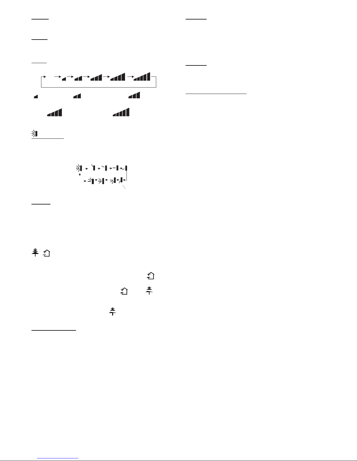
FAN:
This button is used to set the fan speed in the following sequence.
Aut o
Medium speedLow-Medium speedLow speed
High speedMedium-High speed
Fig. 6 - Fan speed
SWING:
Press the SWING button to select five different vertical (up and
down) air discharge directions including Continuous Sweep. The
Swing Louver icon appears. Press this button to set swing angle,
which changes directions as shown below.
OFF
Fig. 7 - Swing buttons
IFEEL:
Press this button to use the I FEEL function, and the icon appears.
The unit senses room temperature at the remote controller instead of
at the indoor unit. It then adjusts airflow and temperature accordingly
for the ultimate in personal comfort control and energy savings.
Press the button again to exit this function. For best performance,
keep remote controller away from heat or cold temperature sources
while using this function.
/
Press this button to achieve the on and off of healthy and
scavenging functions in operation status. Press this button for the
first time to start scavenging function; LCD displays “ ”. Press
the button for the second time to start healthy and scavenging
functions simultaneously; LCD displays“ ”and“ ”. Press
this button for the third time to quit healthy and scavenging
functions simultaneously. Press the button for the fourth time to
start healthy function; LCD display “ ” . Press this button again
to repeat the operation above.
SLEEP MODE:
The unit automatically adjusts room temperature during your sleep
time. This slight change in temperature will not affect your comfort
level due to the natural effects that sleeping has on the body, however
it saves on energy consumption and lowers your electric bill.
The unit has three Sleep Modes to select from. Press the SLEEP
button to select Sleep 1, Sleep 2, Sleep 3 or Cancel. The SLEEP
icon appears.
SLEEP 1
In Cool, Dehumidify modes: sleep status after run for one hour, the
main unit setting temperature increases 1.8_F(1_C),setting
temperature increased 3.6 _F(2_C) , the unit will run at this setting
temperature. In Heat mode: sleep status after running for one hour,
the setting temperature decreases 1.8 _F(1_C), 2 hours, the setting
temperature decreases 3.6_F(2_C), then the unit runs at this setting
temperature.
SLEEP 2
In Sleep 2 the unit adjusts the room set temperature at a rate based
on the starting set temperature value. Sleep Mode continues until
cancelled.
DIY MODE SLEEP 3
1. Under Sleep 3 mode, hold “Turbo” button until the remote
control enters into the user’s individuation sleep setting
status, at this time, the time of remote control displays “1
hour”, the setting temperature “88” displays the
corresponding temperature of the last setting sleep curve
and blink (The first entering displays according to the initial
curve setting value of original factory setting).
2. Adjust the “+” and “- ” button, to change the corresponding
setting temperature. After adjusted, press “Turbo” for
confirmation.
3. At this time, 1 hour will be automatically increased at the
timer position on the remote control, (that are “2 hours” or
“3 hours” or “8 hours”), the place of setting temperature
“88” displays the corresponding temperature of last setting
sleep curve and blink.
4. Repeat the previous steps (2) & (3) operation, until 8 hours
temperature setting finished, sleep curve setting finished, at this
time, the remote control resumes the original timer display;
displays the corresponding temperature of last setting sleep
curve and blinks (The first setting entered displays according
to the initial curve setting value of original factory setting); “2
hours” or “3 hours” or “8 hours”), the place of setting
temperature “88” displays the corresponding temperature of the
last setting sleep curve and blinks; the temperature display
resumes to the original setting temperature. Sleep3- the sleep
curve setting under SLEEP mode by DIY could be inquired:
The user could use the existing sleep curve setting method to
inquire the presetting sleep curve, enter into user individuation
sleep setting status, but do not change the temperature, press
“Turbo” button directly for confirmation.
NOTE: In the above presetting or enquiry procedure, if
continuously within 10s, there is no button pressed, the sleep
curve setting will automatically quit and resume to display the
original displaying. In the presetting or inquiry procedure,
press the “ON/OFF” button, “Mode” button, “Timer”button
or “Sleep” button, the sleep curve setting or inquiry status will
quit similarly. The Sleep mode continues until cancelled.
NOTE: During this procedure, if no button is pressed within 10
seconds, the remote controller automatically exits the sleep
curve setting and resumes the original display. If the ON/OFF,
MODE, TIMER, SLEEP, COOLING or HEATING button is
pressed during the setting or inquiry procedure, the remote
controller exits the sleep curve setting.
NOTE: Sleep function can not be set in AUTO mode.