34
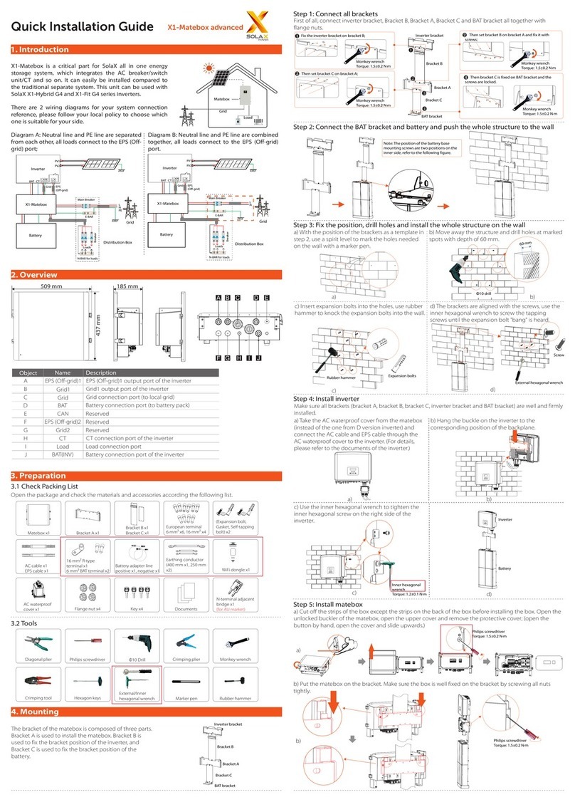
6.2 X3-Matebox advanced side connection
5. Monitor the antenna connections of accessories
6.Wiring Connection
3
6.1 Inverter side connection_PV(INV)
- Grid(INV) and EPS(INV)
N16
E-bar
Grid
※Note: For 5.0 kw and 6.0 kw M series, there
is only one PV1 line, and PV1+/PV1-
corresponds to any pair of PV1+/PV1- ports
on X3-Matebox advanced.
Pv1
+
Pv1
-
Pv1
+
Pv1
-
Pv2
+
Pv2
-
Pv1
+
Pv1
-
Pv1
+
Pv1
-
Pv2
+
Pv2
-
320102044400
6.3 Ground wire connections
Hexagon keys
Torque: 1.5±0.2N·m
The box needs to be grounded as follows.
BAT(+)/BAT(-)
To battery
-
+
- PV and Grid and Load and Battery
Grid(R/S/T/N) Load(R/S/T/N)
PV
Diagonal Plier
Crimping Plier
L=12mm
L
PV Grid(R/S/T/N) Load(R/S/T/N)
L=12mm
L
L
L=12mm
L1
C
L=L1+3mm
C
L=L1+3mm
L1
R S T N
2122 23 24
EPS(INV) Grid(INV)
17 18 19
N20
PE
Grid(INV)
Grid(INV)
R S T N
2122 23 24
EPS(INV) Grid(INV)
17 18 19
20
PE
NN26
A
I
A I
6.4 The N-line on the Grid side is short circuited to the N-line on the EPS side
II
B
R S T N
2122 23 24
EPS(INV) Grid(INV)
17 18 19
20
PE
N
N
25
N26
N-wire connector(130mm, ) 6 mm²
25 26
EPS(INV)
25 26
EPS(INV)
2324
2122
Refer to 6.2
DC Input/Output
Max. Input Voltage
Max. Short Current
Battery Voltage Range
Max. Charge/Discharge Current Installation Specication
Dimension (L*W*H)
Weight
Operating Temperature
Installation
1000V
30A/20A
180-500V
30A/30A
204*533*397mm
7.5kg
-30℃~+60℃
Wall Mounted
GRID Input/Output
Frequency
Max. Grid(INV) input/output current
380/400/415Vac
24.1A
LOAD Input/Output
Rated Grid Voltage
Max. Load/EPS Current
380/400/415Vac
63A/24.1A
7. Technical Parameters
Rated Grid Voltage
50/60Hz
Frequency 50/60Hz
Diagonal Plier
Grid (PE)
3) Pass the PV line through the PV port of the X3-Matebox advanced, and then nd PV(PV1+/PV1-
/PV2+/PV2+) inside the X3-Matebox advanced. Force the wire harness directly into the hole to jam,
gently twist not to loosen.
4) Pass the Grid/Load line through the Grid/Load port of the X3-Matebox advanced, then nd the
Grid(R/S/T/N) port and Load (R/S/T/N) ports in the X3-Matebox advanced, insert each line, and use
the screwdriver to lock the screws.
5) Pass the battery power wire through the BAT port of The X3-Matebox advanced, then nd the
BAT+ and BAT- ports in the X3-Matebox advanced, insert each wire accordingly, and use the
screwdriver to lock the screws.
-If the user requires wiring rules for neutral wires the standby power supply cannot be
isolated or switched (for wiring Australia and New Zealand regulations AS/NZS_3000:2012)
6.5 Finally, use the screwdriver to install the baffle back, close the upper cover
and lock the buckle by hand.
b) Grid(PE) strip the grounding cable insulation(length”L’’), insert the stripped cable into the R type
terminal, and then clamp it.
2) PV(PV1+/PV1-/PV2+/PV2-) /Grid(R/S/T/N/PE) /Load(R/S/T/N) side connection
a) Prepare ordinary 4mm² PV(PV1+/PV1-/PV2+/PV2-) /10mm² Grid(R/S/T/N/PE) /10mm² Load(R/S/T/N)
remove the 12mm insulation layer at the end of the wire. Insert the European-style terminals
respectively.
The stripped terminals must be inserted into the European-style terminals and nally pressed down
with the crimping pliers.
Note: According to the different N terminals of Grid(INV ), select the corresponding
connection position.(if need:(A + 6.4B) or (I + 6.4II))
1) Connect the Grid(INV ) R/S/T/N and EPS (INV ) R/S/T/N/PE ports of the inverter to the X3-Matebox
advanced port. The connection method is as follows :
a) First, insert the R/S/T EPS(INV ) into the R/S/T port of EPS (INV ) in X3-Matebox advanced and the N
EPS(INV ) directly into the hole, directly into the hole and ensure that the installation is tight ;
b) Then nd the Grid(INV ) (R/S/T ) port in X3-Matebox advanced, connect the corresponding wire
harness, and lock the screw with a screwdriver.
C) Finally, lock the PE wire/N wire with a hexagonal keys;
Note: 5.0 kw and 6.0kw M. series inverters have only two MPPT and two PV strings, so when connecting,
you need to unplug ①/② of the PV in the X3-Matebox advanced.
-Use a screwdriver to press down the yellow part while pulling the wire out of the port.
According to the PV 1(INV )+/PV1(INV )-/PV2(INV )+/PV2(INV )-/BAT(INV )+/BAT(INV )- line symbol on X3-
Matebox advanced harness, the corresponding ports of PV 1+/PV1-/PV2+/PV2-/BAT+/BAT- of the
inverter are successively inserted.
There is an antenna in the box of monitoring accessories.
a) Install the antenna on the box and tighten it by hand;
b) Then connect the antenna cable to the end of the WiFi Dongle.


