Solectron Invotronics DCX KeyFob User manual

365 Passmore Avenue
Scarborough, Ontario M1V 4B3
TEL: 416-321-8822
FAX: 416-321-8823
DCX KeyFob
Operations Manual
Prepared by: Sam Baruco
Michael Ahrens
Yarko Matkiwsky
Date: April 2, 2007
Revision: 1.45

DCX KeyFob Module
Operations Manual
NOTICE TO USER.......................................................................................................................................1
PURPOSE......................................................................................................................................................1
SKIM IMMOBILIZER ................................................................................................................................1
REMOTE KEYLESS ENTRY.....................................................................................................................2
TO UNLOCK DOORS: ................................................................................................................................... 2
TO LOCK DOORS:........................................................................................................................................ 2
PANIC ALARM: ........................................................................................................................................... 2
REMOTE START: ......................................................................................................................................... 2
NOTES: ....................................................................................................................................................... 2
KEYFOB POWER SUPPLY........................................................................................................................3
TECHNICAL SPECIFICATIONS..............................................................................................................4
KEYFOB MECHANICAL DESIGN.................................................................................................................. 4
RKE WIRELESS SPECIFICATIONS................................................................................................................ 4
RKE Transmitter -- General Wireless Specifications ........................................................................... 4
Center Frequency, Accuracy, and Stability .......................................................................................... 4
Operating Stability with Voltage Variation / Low Battery.................................................................... 4
Output Power Limits and Stability........................................................................................................ 5
Modulation Index (ASK Mode)............................................................................................................ 5
Intra-Transmission Stability ................................................................................................................. 5
Carrier Attack / Close Time.................................................................................................................. 5
KEYFOB OPERATING TEMPERATURES........................................................................................................ 5
Physical Device Classification.............................................................................................................. 5
NOMINAL SYSTEM RANGE REQUIREMENT ................................................................................................. 6

DCX KeyFob Module
Operations Manual
DCX_KeyFob_UserManual_1.45_2007Apr2.doc 1
Notice to User
Caution: Changes or modifications not expressly
approved by the party responsible for compliance
could void the user's authority to operate the
equipment.
FCC Information to Users:
This device complies with part 15 of the FCC Rules. Operation is subject
to the following two conditions: (1) This device may not cause harmful
interference, and (2) this device must accept any interference received,
including interference that may cause undesired operation.
Purpose
The DCX KeyFob Module interfaces with the vehicle WCM (Wireless Control
Module). The KeyFob houses a RKE (Remote Keyless Entry) transmitter and SKIM
(Sentry Key Immobilizer Module) transceiver.
SKIM Immobilizer
The SKIM Immobilizer Key prevents unauthorized operation of a vehicle by
disabling the engine. This system utilizes ignition keys which have an embedded
electronic chip (transponder). The vehicle can only be started and operated by keys that
have been programmed to the vehicle. Once a key has been programmed to a vehicle, it
cannot be programmed to any other vehicle.
Operation of the SKIM Immobilizer system is automatic and does not require user
activation.
The SKIM Immobilizer communicates with the WCM via an inductive coupled
link at a frequency of 125Khz.

DCX KeyFob Module
Operations Manual
DCX_KeyFob_UserManual_1.45_2007Apr2.doc 2
Remote Keyless Entry
This hand-held radio transmitter allows you to lock/unlock the doors, remotely
start and activate the panic alarm within a 30meter range of the vehicle.
To Unlock doors:
Press and release the UNLOCK button on the RKE Transmitter once to
unlock.
To Lock doors:
Press and release the LOCK button on the RKE Transmitter once to lock.
Panic Alarm:
Press and release the PANIC button on the RKE Transmitter once to turn
the Panic Alarm On and Off.
Remote Start:
Press and release the REMOTE START button on the RKE Transmitter twice
to remotely start the vehicle.
Notes:
If any of the buttons are pressed and not released within a 30 second duration the RKE
Transmitter will stop transmitting and shut down to prevent battery drainage.

DCX KeyFob Module
Operations Manual
DCX_KeyFob_UserManual_1.45_2007Apr2.doc 3
KeyFob Power Supply
The KeyFob operates on a 3V Manganese Dioxide Lithium Coin Battery (CR2032).
Minimum operating voltage is approximately 2.6V, if the voltage drops below this level
the transmitter will cease operation, and the battery will need to be replaced. Please
replace battery with the aforementioned part number.
With the transmitter buttons facing down, use a thin coin to pry the two halves of the
transmitter apart. Use care to ensure that the rubber gasket is not damaged during
removal.
Remove and replace the batteries. Avoid touching the new batteries with your fingers.
Skin oils may cause battery deterioration.
Do not touch the printed circuit board or the battery terminals that are on the back
housing.
To reassemble the transmitter case, snap two halves together. Make sure there is and even
‘gap’ between the two halves.
Test Transmitter operation.

DCX KeyFob Module
Operations Manual
DCX_KeyFob_UserManual_1.45_2007Apr2.doc 4
Technical Specifications
KeyFob Mechanical Design
The KeyFob has six mechanical components.
1. Component Mounted PCB.
2. Elastomer Buttons.
3. Battery Clip.
4. Plastic Housing (Top & Bottom Halves).
5. Metal Key-Blade.
6. Key Ring.
RKE Wireless Specifications
Stabilized by a SAW resonator, the resonant frequency is generated by an oscillator
transmitting on a frequency of 315MHZ, within an accuracy of +/-75kHz.
RKE Transmitter -- General Wireless Specifications
Parameter Specification Units
Center Frequency, Accuracy, and Stability
Center Frequency (Carrier) 315.000 MHz
Accuracy +/- 75 kHz
Stability +/- 75 kHz
Polarization Ratio
(between any two axes)
5 (with linearly polarized receiving
antenna)
dB
Load Induced Frequency Shift +/- 40 kHz
Operating Stability with Voltage Variation / Low Battery
Output Power Stability 5 dB
Frequency Shift +/- 20 kHz

DCX KeyFob Module
Operations Manual
DCX_KeyFob_UserManual_1.45_2007Apr2.doc 5
RKE Transmitter -- General Wireless Specifications
Parameter Specification Units
Output Power Limits and Stability
Output Power <= 81.0 dB μV/m
(peak)
Output Power Stability +/- 3 dB
Modulation Index (ASK Mode)
ON-OFF Ratio 40 dB
Intra-Transmission Stability
Output Power 1
(bit-wise peak power across packet)
dB
Center Frequency +/- 10 kHz
Timing +/- 1 %
Carrier Attack / Close Time
Attack Time 25 μsec
Close Time 50 μsec
KeyFob Operating Temperatures
Parameter Minimum Maximum
Physical Device Classification
RKE Feature OpTemp -20oC+70oC
SKIM Feature OpTemp -40oC+85oC
Storage Temperature (ExpTemp) -40oC+85oC
Humidity (Operation) <2% RH >99% RH
DCX KeyFob Module
Operations Manual
DCX_KeyFob_UserManual_1.45_2007Apr2.doc 6
Nominal System Range Requirement
Reliability Distance Units
100% (0% Failure) 20 m
> 90% (<10% Failure) 25 m
> 75% (<25% Failure) 30 m
> 25% (<75% Failure) 40 m
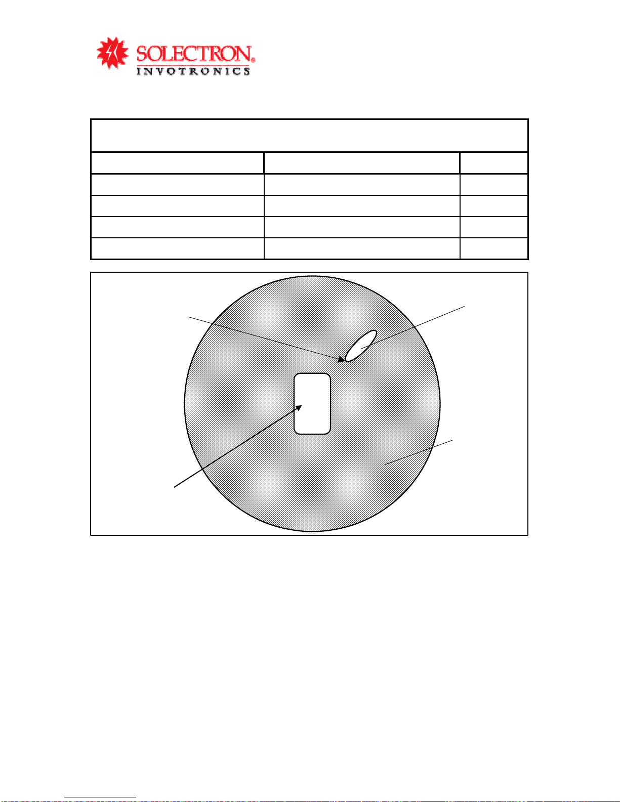
Null
Region
Control Range
Measurment
RKE
Response
Region
Vehicle
Control Range
Measurement
Table of contents


