Sollae EZI-10 User manual

Caution: Specifications of this document may be changed without prior notice for
improvement.
Sollae Systems Co., Ltd.
http://www.sollae.co.kr
ezTCP Technical Documents
Internet Switch (EZI-10)
Version 1.1

Internet Switch (EZI-10) Ver. 1.1
Sollae Systems Co., Ltd.
- 1 -
http://www.sollae.co.kr
Contents
1Overview ..................................................................................................................................- 2 -
2Configuration ..........................................................................................................................- 3 -
2.1 Master .....................................................................................................................................................................- 3 -
2.1.1
Setting Network Parameters ...............................................................................................................- 3 -
2.1.2
Setting TCP/IP Parameters....................................................................................................................- 4 -
2.2 Slave.........................................................................................................................................................................- 5 -
2.2.1
Setting Network Parameters ...............................................................................................................- 5 -
2.2.1
Setting TCP/IP Parameters....................................................................................................................- 6 -
3Operation .................................................................................................................................- 7 -
3.1 Basic Operation...................................................................................................................................................- 7 -
3.2 Advanced Operation ........................................................................................................................................- 8 -
4Revision History......................................................................................................................- 9 -
Internet Switch (EZI-10) Ver. 1.1
Sollae Systems Co., Ltd.
- 2 -
http://www.sollae.co.kr
1 Overview
EZI-10 is a remote digital I/O Controller. This device lets us not only control remote
devices’output but also monitor remote devices’input. There are two ways for the
communication on TCP/IP.
The one is HTTP. This way is quite simple because you can use it just running a web
browser. You don’t need to make an application.
The other one is Modbus/TCP. This way allows users to set some detailed and
complicated operations. To use Modbus/TCP, you should make an application or use the
ModMap which is a Modbus/TCP application offered by us for free.
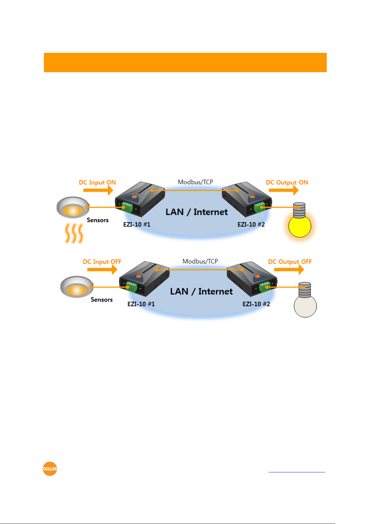
This document describes an example of “Internet Switch”application.
Figure 1-1 an application of Internet Switch (switch ON)
Figure 1-2 an application of Internet Switch (switch OFF)
You are allowed to control remote digital output by using two of EZI-10 as you can see
in the above systems.
Internet Switch (EZI-10) Ver. 1.1
Sollae Systems Co., Ltd.
- 3 -
http://www.sollae.co.kr
2 Configuration
2.1 Master
Modbus/TCP consists of a master and slaves. A master sends queries to the slaves and
slaves reply the queries. You have to designate which one will be a master or which one
will be a slave considering your network environment.
2.1.1 Setting Network Parameters
ezConfigIO is the tool for configuring parameters of EZI-10.
Connect EZI-10 to your network and run ezConfgIO on your PC. Referring to the below
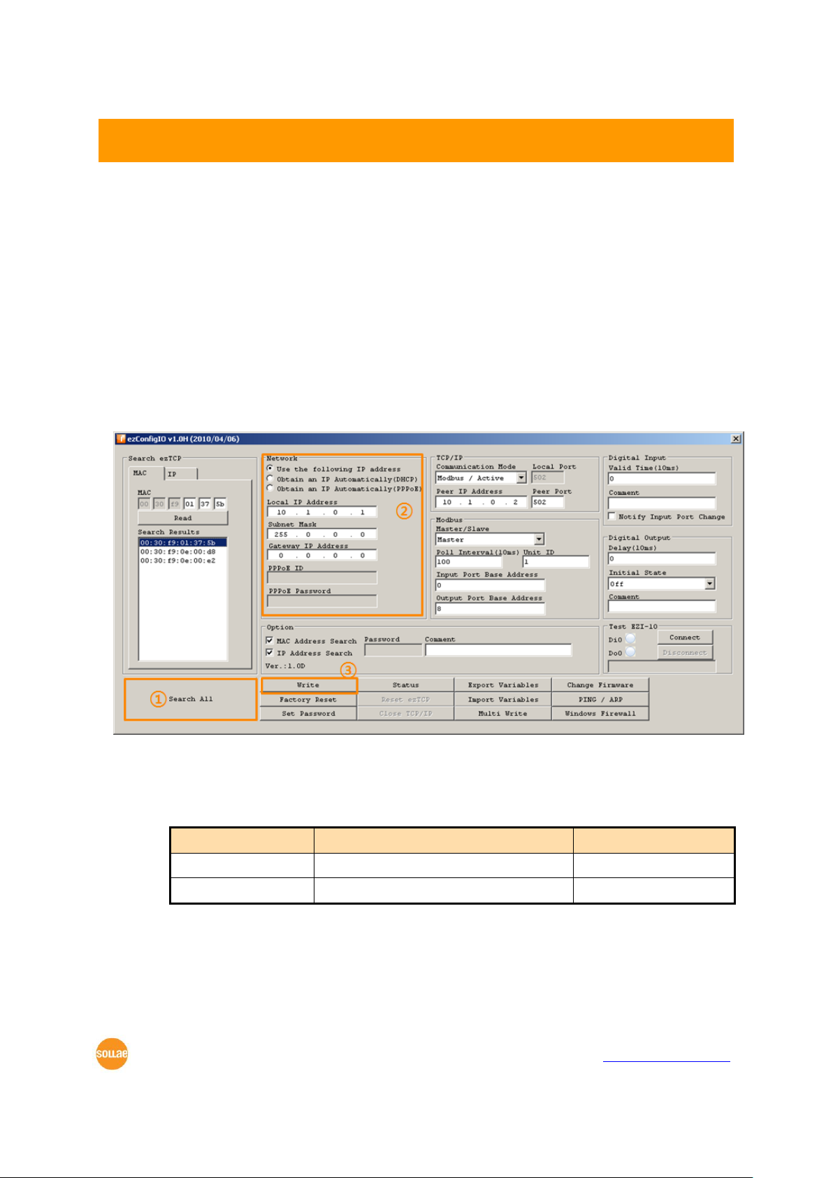
figure, set network parameters.
Figure 2-1 network configuration of the master
①Press the [Search All] button.
②Set network parameters.
Table 2-1 network parameters
Parameter
Description
Value
IP Assignment
Automatically or Manually
Manually
IP Address
IP Address for the master
10.1.0.1
③Click the [Write] button.
Internet Switch (EZI-10) Ver. 1.1
Sollae Systems Co., Ltd.
- 4 -
http://www.sollae.co.kr
2.1.2 Setting TCP/IP Parameters
To communicate on Modbus/TCP, a master and a slave should be connected on TCP. The
one which tries to make connection sending [SYN] segments is called TCP client and the
one which waiting connection request segments from clients is called TCP server. Usually, a
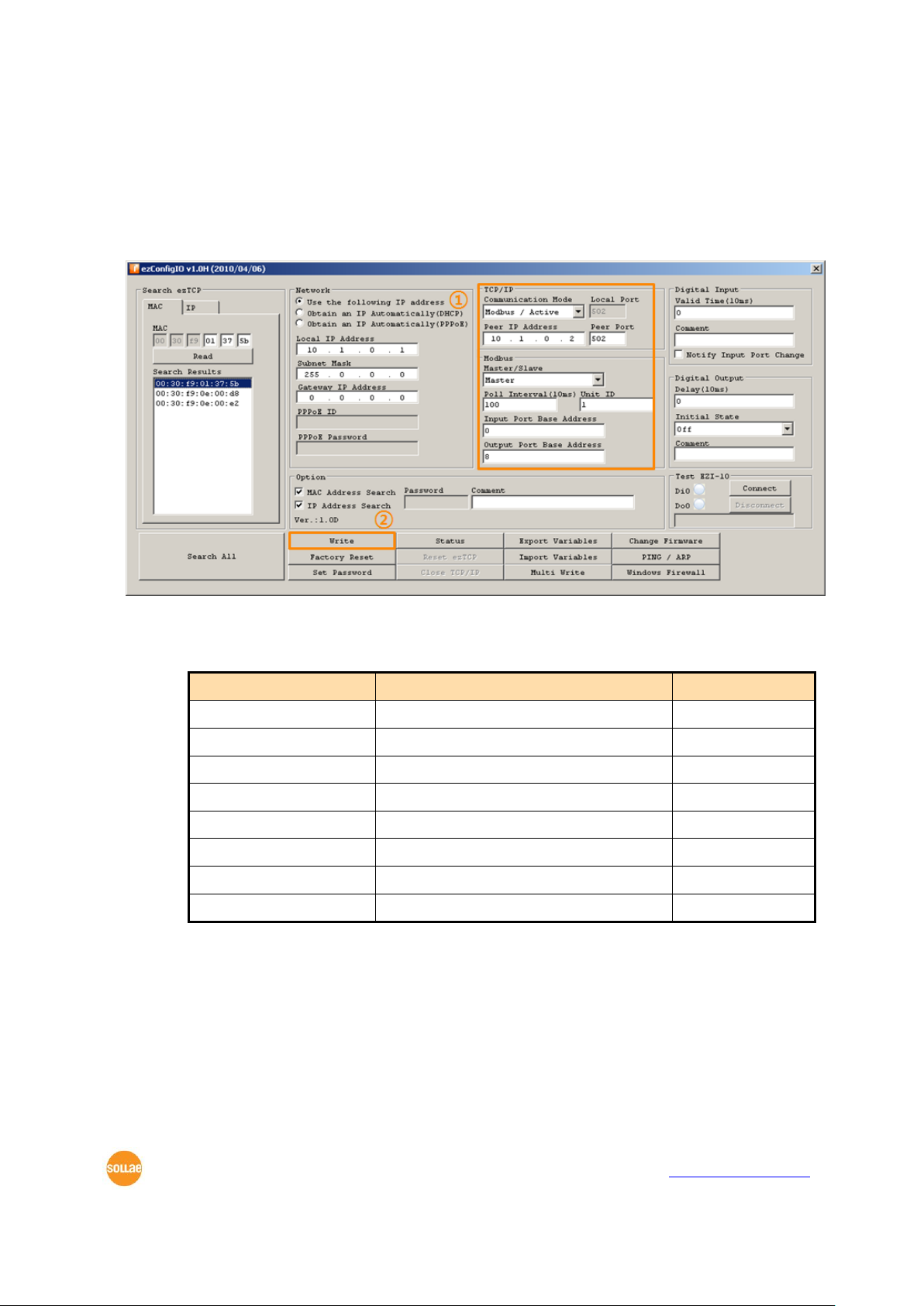
master is set to a TCP client. (Modbus / Active)
Figure 2-2 TCP/IP configuration of the master
①Set the TCP/IP parameters. (Set parameters referring to the below table)
Table 2-2 TCP/IP parameters
Parameter
Description
Value
Comm. Mode
TCP Active or Passive connection
Modbus / Active
Peer IP Address
Slave’s IP Address
10.1.0.2
Peer Port
Port number for communication
502
Master / Slave
Mode selection
Master
Poll Interval
Interval for sending queries
100 (1sec)
Unit ID
ID of a pairs of a master and a slave
1
Input Port Base Addr.
Input Port Base Address
0
Output Port Base Addr.
Output Port Base Address
8
②Click the [Write] button.
It is okay to set the master to TCP server (Modbus / Passive) if you need it.
Internet Switch (EZI-10) Ver. 1.1
Sollae Systems Co., Ltd.
- 5 -
http://www.sollae.co.kr
2.2 Slave
2.2.1 Setting Network Parameters
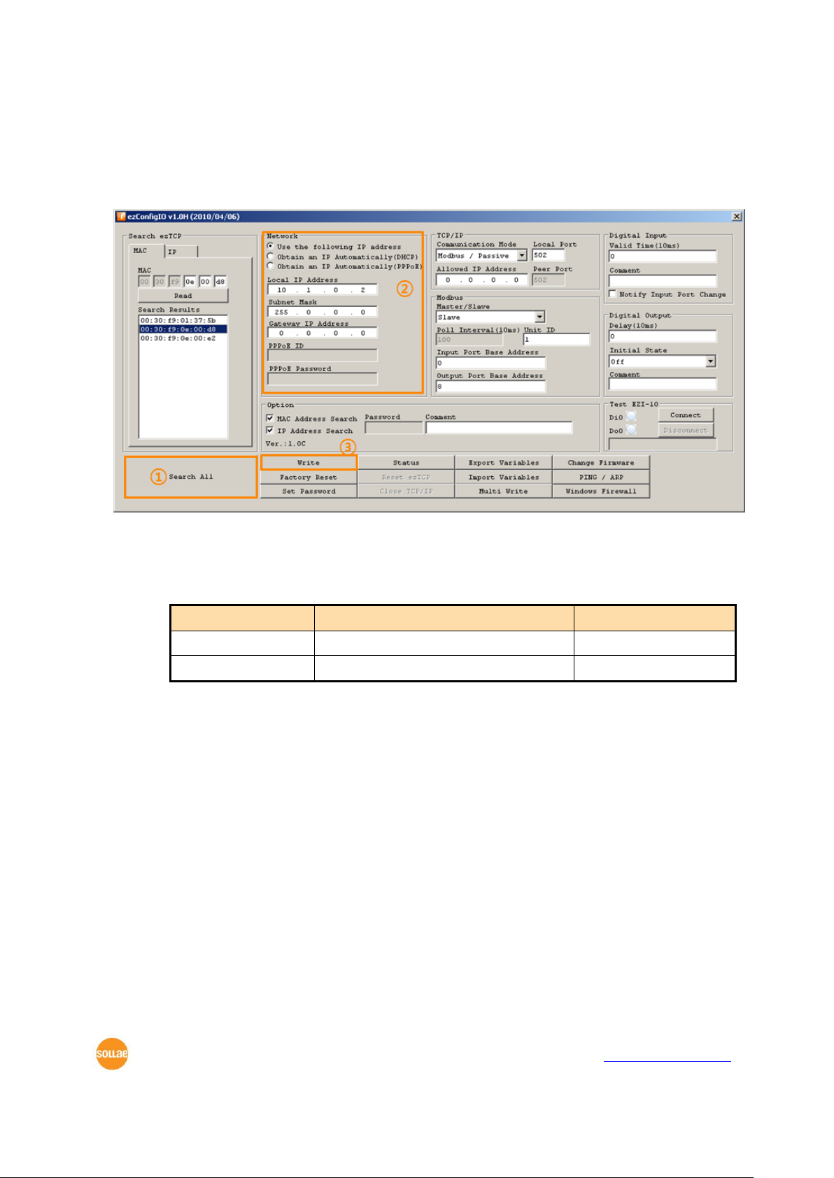
The way of setting network parameters of slaves is the same with the master’s.
Figure 2-3 network configuration of the slave
①Press the [Search All] button.
②Set network parameters.
Table 2-3 network parameters
Parameter
Description
Value
IP Assignment
Automatically or Manually
Manually
IP Address
IP Address for the slave
10.1.0.2
③Click the [Write] button.
Note that the each IP address of the master and slave shouldn’t be the same.

Internet Switch (EZI-10) Ver. 1.1
Sollae Systems Co., Ltd.
- 6 -
http://www.sollae.co.kr
2.2.1 Setting TCP/IP Parameters
Usually, a slave is set to a TCP server. (Modbus / Passive)
In case that the master is set to a TCP server, the slave should be a TCP client.
Figure 2-4 TCP/IP configuration of the slave
①Set the TCP/IP parameters. (Set parameters referring to the below table)
Table 2-4 TCP/IP parameters of the slave
Parameter
Description
Value
Comm. Mode
TCP Active or Passive connection
Modbus / Passive
Local Port
Port number for communication
502
Allowed IP Address
Allowed IP address for TCP connection
0.0.0.0
Master / Slave
Mode selection
Slave
Unit ID
ID of a pairs of a master and a slave
1
Input Port Base Addr.
Input Port Base Address
0
Output Port Base Addr.
Output Port Base Address
8
②Click the [Write] button.

Internet Switch (EZI-10) Ver. 1.1
Sollae Systems Co., Ltd.
- 7 -
http://www.sollae.co.kr
3 Operation
3.1 Basic Operation
There are two basic operations in this application.
Automatic Control of the Master’s OUTPUT by the Slave’s INPUT
Figure 3-1 basic operation 1
Automatic Control of the Slave’s “OUTPUT by the Master’s INPUT
Figure 3-2 basic operation 2

Internet Switch (EZI-10) Ver. 1.1
Sollae Systems Co., Ltd.
- 8 -
http://www.sollae.co.kr
3.2 Advanced Operation
You can use this application in detail by using the below parameters.
Figure 3-3 advanced operation
Valid Time
EZI-10 recognizes that the input signal is valid only if the signal keeps HIGH for the
value of [Valid Time]. That means all shorter signals than the value of [Valid Time] are
ignored. The unit is 10ms.
Notify Input Port Change
This option lets EZI-10 send response segments to the counterpart immediately when
its input port state has been changed without queries.
Delay
EZI-10 delays output as much as time set to the value of [Delay]. The output signal
should be maintained by the point of operation time and any other outputs can be
acceptable when timer is running by this option. The unit is 10ms.

Internet Switch (EZI-10) Ver. 1.1
Sollae Systems Co., Ltd.
- 9 -
http://www.sollae.co.kr
4 Revision History
Date
Version
Description
Author
2011.04.07
1.0
○This document has been initially released.
Roy LEE
2013.02.07
1.1
○Update some figures(specifying Power type)
Roy LEE
Table of contents
Popular Switch manuals by other brands

Cabletron Systems
Cabletron Systems 9E423-36 owner's manual

HP
HP 6125XLG Configuration guide

Cisco
Cisco 6503 - Catalyst Firewall Security Sys supplementary guide

LEGRAND
LEGRAND 695 03 manual

Moxa Technologies
Moxa Technologies EtherDevice EDS-728 Series Hardware installation guide

Cisco
Cisco 3750 - Catalyst EMI Switch datasheet

Topspin
Topspin 120/Cisco SFS 7000 quick start guide

CZHOON
CZHOON CZH-T287 user manual

ASTEL CCTV
ASTEL CCTV TS 081 operating instructions

Cross Technologies
Cross Technologies 1582-225L2 instruction manual

KBC
KBC ESUGS4-EG1-P1-D quick start guide

ZyXEL Communications
ZyXEL Communications GS1200-5HP v2 user guide


