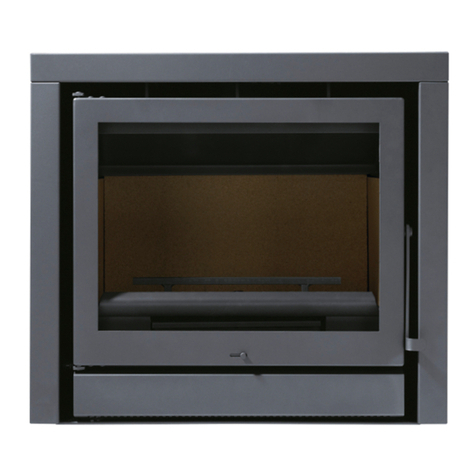
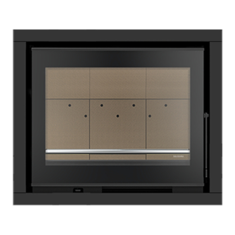
SOLZAIMA EARTH 9KW User manual

Pellet Insert
Instruction Manual
Models
FIRE 9KW | EARTH 9KW |
WIND 9KW
Read these instructions carefully before installing, using and servicing the unit. The
instruction manual is an integral part of the product.
Mod.814-D

1
Thank you for purchasing a SOLZAIMA appliance.
Please read this manual carefully and keep it for future reference.
* All our products fulfil the requirements of the Construction Products Directive
(Directive 89/106/EEC) and have been approved with the CE conformity mark;
* The Pellet Burning Free Standing Fires are designed according to EN 14785:2008
Standards
*SOLZAIMA disclaims any responsibility for damages to the unit if installed by non-
qualified personnel;
* SOLZAIMA is not responsible for any damage to units not installed and used in
compliance to the instructions included in this manual;
* All local regulations, including but not limited to national and European standards,
must be observed when installing, operating and servicing the unit;
* Whenever you need assistance, you should contact the supplier or installer of your
equipment. You should provide the serial number of your stove that is located on the
nameplate on the back of the equipment and on the sticker s glued to the plastic cover
of this manual.
*The technical service must be performed by the unit Installer or Supplier, except on
situations where the assessment performed by the installer or service engineer
determines that SOLZAIMA should be contacted, if required.
Contacts for technical support:
www.solzaima.pt
apoio.client[email protected]
Address: Rua dos Outarelos; nº 111;
3750-362 Belazaima do Chão
Águeda - Portugal

2
Table of Contents
1. Package Content....................................................................................................... 4
1.1. Unpacking the insert............................................................................................ 4
1.2. ............................................................................................................................... 4
2. Safety Precautions .................................................................................................... 6
3. Advice on action in the event of a fire in a chimney (including equipment). ...................... 7
4. Technical Specifications ............................................................................................. 8
5. Installing the Free Standing Pellet Fire....................................................................... 10
6. Installation of optional accessories. ........................................................................... 20
7. Intallation requirements .......................................................................................... 31
8. Installation for exhaust gas systems: ........................................................................ 32
8.1. Installing Without a Chimney .............................................................................. 32
8.2. Installation with a Chimney ................................................................................ 36
9. Fuel ...................................................................................................................... 37
10. Use of the pellet insert ............................................................................................ 38
11. Remote Control ...................................................................................................... 39
11.1. Infrared Remote Control .............................................................................. 39
11.2. Control and Display Panel ............................................................................. 39
11.3. ................................................................................................................. 39
11.4. Display Information Summary ....................................................................... 40
11.4.1. Selecting the Manual or Automatic Mode ................................................... 40
11.4.2. Date and Time ....................................................................................... 40
11.4.3. Timer ................................................................................................... 43
11.4.4. Sleep (this menu is displayed only while the unit is operating). .................. 46
11.4.5. Info...................................................................................................... 47
11.4.6. Settings Menu ....................................................................................... 50
12. Alarm / Failure / Recommendation List ...................................................................... 55
13. Start-up................................................................................................................. 57
13.1. Stop........................................................................................................... 57
13.2. Turning Off the Unit ..................................................................................... 57
14. Control and Display –Columbus Electronics ............................................................... 58
14.1. Internal Display........................................................................................... 59
15. External Display...................................................................................................... 61
15.1. General Menu - Settings Menu....................................................................... 62
15.1.1. Settings Menu –Language............................................................................ 62
15.1.2. Settings Menu - Date and Time ..................................................................... 64
15.1.3. Settings Menu - Remaining Options................................................................ 65
15.2. General Menu.............................................................................................. 68
15.2.1. General Menu - Power Menu.......................................................................... 68

3
15.2.2. General Menu - Service Menu........................................................................ 71
15.2.3. General Menu - Thermostats Menu................................................................. 76
15.2.4. General Menu - Chrono Menu ........................................................................ 77
16. List Alarms / malfunctions / recommendations............................................................ 83
17. Instruction for installing the frame ............................................................................ 85
17.1. Choice of frame ........................................................................................... 85
17.2. Installation of the frame on the equipment ..................................................... 87
18. Replenishment of pellets .......................................................................................... 88
19. Maintenance........................................................................................................... 91
20. Maintenance Plan and Log........................................................................................ 99
21. Maintenance Guide Label .......................................................................................103
22. Electrical Diagram of the Free Standing Fire Unit........................................................104
22.1. Electrical schematic –Not applicable to Columbus Electronics...........................104
22.2. Electrical Schematic –Columbus Electronics...................................................104
23. End of life of a pellet insert .....................................................................................105
24. Warranty ..............................................................................................................105
24.1. Warranty general conditions.........................................................................105
25. Annexes ...............................................................................................................113
25.1. Flow chart..................................................................................................113
25.2. Statement of Performance ...........................................................................116

4
1. Package Content
The packaging of the equipment has the following contents:
- Pellet Insert models: Fire 9kW, Earth 9kW or Wind 9kW;
- Handle for opening the door and extracting the equipment;
- Power cable;
- Infrared remote control;
1.1. Unpacking the insert
•To unpack the equipment, you must first remove the retractable bag that
surrounds the carton box. Then remove the box by lifting it up and removing
the bag wrapping the insert and the Styrofoam plates.
•The insert has a fixed part and a movable part which can be separated. To
separate the two parts, first open the two safety latches under the door, use
the accessory to make it easier to open.
Figure 1 –Open safety latches

5
•With the two latches open, use them as pullers to separate the movable part from
the fixed part attached to the pallet.
•Notice. When you open the runner system to the limit, you notice a ledge that
locks the moving part, as the ledge passes, the slides are released and the equipment
may fall. You have to be careful that this does not occur. The movable part of the fixed
part is then separated.
•The surfaces on which the parts are supported must be protected.
Figure 2 –Separate moving and fixed parts
• With the help of a star wrench PZ2 remove the two screws securing the fixed part
to the pallet, the equipment is thus completely unpacked.
Figure 3 –Separate parts

6
2. Safety Precautions
•Make sure you fully read and understand the instructions contained in this manual
before using the pellet insert as a biomass heating unit.
•The pellet insert is not intended for use by children or people physically and/or
mentally challenged, or that are inexperienced or unfamiliar with using the unit, except
when under supervision or after receiving proper training.
•Do not touch the pellet insert when barefoot or if any part of your body are wet or
humid;
•Do not tamper with the safety devices or adjustment features without the
SOLZAIMA SA manufacturer's authorization;
•It is prohibited to cover or reduce the size of the ventilation openings of the
installation;
•The pellet insert is an equipment that requires air to have a proper combustion, the
possible Airtightness of the place where the equipment is located or the existence of
other sources of air extraction in the house can prevent the correct functioning of the
equipment;
•The existence of vents is a requirement for proper combustion;
•Please keep the packing materials away from children;
•During normal operation, DO NOT open the door of the unit;
•Some parts may overheat during normal operation, so the direct contact with hot
parts such as the door handle and glass should be avoided;
•Check for the existence of any obstructions to the fume duct before turning on the
unit after a long idle period;
•The pellet insert is designed to work inside a protected environment. Safety
systems may be used to turn off the insert. If this happens, contact the after-sales
service and never in any situation disarm the safety systems;
•The pellet insert is a biomass heating unit equipped with an electric fume extractor.
The occurrence of a power failure during its use may prevent the fume to be extracted,
consequently causing the room to be filled with smoke. For this reason, a natural fume
extraction system, like a chimney, is recommended;
•NEVER turn off an operating Free Standing Pellet Fire unit by disconnecting the
electric plug. The fume extractor on the Free Standing Pellet Fire unit is a powered
feature, so disconnecting the power plug will prevent the extraction of combustion
fumes;

7
•The unit must be disconnected from the mains power before any maintenance
procedures can be performed. Please allow the unit to cool down completely before any
maintenance operation (if operating before);
•Never touch the interior of the unit without disconnecting it from the power mains.
3. Advice on action in the event of a fire in a chimney
(including equipment).
• Try to put out the fire, without risking your life.
• If you cannot put out the fire within a minute, you should call the fire department.
• Close the doors and windows or partition where the fire has flared.
• Turn off the power and close the gas before leaving your home.
• Once outside, you must wait for the firemen and be ready to give them the
following information: location of the fire, possible materials that are burning and what
they can do to prevent fire progression.

8
4. Technical Specifications
Features
Fire 9kW
Earth 9kW
Wind 9kW
Units
Weight
112
114
116
kg
Height
546
606
546
mm
Width
688
688
688
mm
Depth
573
mm
Diameter of the fume discharge pipe
80
mm
Reservoir capacity
15
kg
Maximum heating capacity
188
m³
Maximum overall thermal power
8,3
kW
Minimum thermal power
3,2
kW
Minimum fuel consumption
0,7
kg/h
Maximum fuel consumption
1,9
kg/h
Rated electrical current
106
W
Electric power at start-up (<10 min.)
350
W
Rated voltage
230
V
Nominal frequency
50
Hz
Thermal yield at rated thermal power
90,1
%
Thermal yield at reduced thermal power
96
%
Max. smoke temperature
154
ºC
Min. smoke temperature
66,3
ºC
CO emissions at rated thermal power
0,01/0,035
%
CO emissions at reduced thermal power
10,35/8,74
%
Combustion gas mass flow
6,3/2,6
g/s
Draught in the chimney
12/10
Pa
Fan Flow
48,2
dB(A)
Table 1 –Technical specifications
Tests were performed using wood pellets with a heating capacity of 4.9 kWh/kg.
The above information was obtained during product homologation tests conducted by
independent laboratories accredited for pellet unit testing.

9
General Measures
Front Back Side Top
Fire 9kW
Earth 9kW
Wind 9kW
Figure 4 –Insertable dimensions to pellets

10
5. Installing the Free Standing Pellet Fire
Before you begin the installation, perform the following actions:
•The recommended measures for installing the pellet insert are as follows:
Model
Width (mm)
Height (mm)
Depth (mm)
Fire 9Kw
695
550
550
Earth 9Kw
695
610
550
Wind 9Kw
695
550
550
•As can be seen in figure 4 the inserts have finishing frames to cover bigger holes,
giving greater versatility to the insert. There are two different widths, one of 44 mm
and one of 74 mm to finish the equipment’s installation (see point 13).
•The surface where the base of the equipment is to be fixed must be leveled and
have the necessary strength to support the entire weight of the equipment and its
subsequent movements to load pellets.
•The base of the equipment has 7 holes to attach to the support.
Figure 5 –Fixing base equipment
• As can be seen in Figure 5, a distance of 62.5mm from the base to the front of the
wall must be left (it must be perfectly parallel).
• The equipment has an approximate weight of 100 kg and when it is extracted to the
pellet / maintenance position, it exerts a high force on the base, during installation it is
necessary to use anchoring material suitable for the type of base, soil and wall (In the
case of extending table), recommendations:

11
Material
Type of attachment
Image
Massive (slab, stone)
FMS M8x60 Ø10
Metallic
Massive and non-massive
(brick)
FIP M8x60 Ø10
Chemical
• It is very important that the base where the insert is installed is completely
horizontal.
• If you do not have a base, the optional extendable table is available. This table is a
metal structure that must be fixed to the floor and to the wall. The table can be
adjustable in height between 300 mm (minimum) and 545 mm (maximum), it is very
important to ensure that the top is perfectly horizontal for the correct operation of the
equipment. Together with the extendable table, screws are deliverd to secure the base
of the insert to the table, with the same 7 screws, it is possible to attach the
equipment to an existing base. Instructions given in point 6.
Figure 6 –Optional extendable table
• Connect the 80 mm diameter pipe between the flue gas outlet and the flue outlet to
the outside of the building (eg fireplace) in accordance with the installation drawings.

12
• After securing the base of the equipment and the chimney being installed place the
moving part of the equipment as shown in figure 7.
Figure 7 –Installation
•Then do a rotating motion to bring the equipment to the horizontal.
Figure 8 –Installation
•Push the movable part to the wall so that it slides on the rails. Check the
correct sliding and that everything is properly attached before continuing with the
intallation. Move the equipment to the end of runner system with open safety latches

13
and once in position, close them to ensure that the equipment is properly placed in the
working position.
Figure 9 –Installation
• Connect the power cord to a 230V 50Hz grounded outlet.
Figure 8 –Electrical connection
• After connecting the power cable to the silo column, it is necessary to attach the
cable to the same column and the base, making sure to leave enough cable length, so

14
that the equipment can make the entire route in the rails (500 mm), without the cable
being stressed or touching the hot parts (Figure 11).
Figure 11 –Electrical connection
• Standard installation of the insert:
Figure 12 –Electrical connection

15
Instalation WIND 9kW
In case of the Wind 9kW it will be necessary to install the pellet feeding system. To
install this loading system it is necessary to open a 330x330 mm hole.
• The position of the loading system has to maintain a ratio where X is always less than
Y = X * 0.7. (See Figure 13), so that we can ensure that the slope is sufficient so that
the pellets are not trapped in the tube connecting the loading mouth with the top of
the insert structure. The loading mouth can be installed in any of the walls that form
the surroudings where the equipment is installed, either to the right or to the left, as in
the front or rear, if the layout of the house allows it. It is always necessary to respect
the minimum distances X = 390 mm, Y = 275 mm Example: X = 450 mm Y = 450x0.7
= 315 mm (minimum).
• The tube used to attach to the loading mouth and top of the insert chassis must have
an internal diameter of 200mm and must be rigid enough not to deform when the
pellets fall inside. It is recommended to apply flexible aluminum tube.
• To attach the drop tube of the pellets to the loading mouth of the top of the insert
chassis it is recommended to use metal clamps. This type of clamps provides good
clamping and sealing, and it is possible to open or close the clamp when necessary.
Figure 9 –Feeding system installation

16
• The easiest way to install the tube will be to perform the following steps:
1- Using the metal clamp, attach the pre-cut tube with the appropriate size and shape
onto its final position in the loading mouth.
Figure 10 –Installation of the loading tube and metal clamp.
2- Insert the assembly through the hole made in the wall with the above mentioned
measurement 330x330 mm, respecting the dimensions for its positioning indicated
above, it is necessary to fix the loading mouth.
3º- To be fixed to the wall, the loading system has four 6 mm holes in diameter. It is
recommended to use 8mm SX bushings for brick walls with 4.5 or 5.5 bolts and 8mm
HM bushes for plasterboard walls (Pladur) with the corresponding screws.
Figure 11 –Mouthpiece installation
4º After fastening the loading piece, place the finishing frame with the cover. Fix the
frame by tightening the 4 load screws on the wall. The cover has a pin limiting its the
opening, as can be seen in the following figure, with a cut of the base assembly,
finishing ring and loading cover.

17
Figure 12 –Equipment installation
5º- When opening the lid, the inner parts are positioned to facilitate the loading of the
pellets, for this reason it is very important that the cargo mouth is always placed in the
position shown in Figure 16.
6º- As shown in Figure 16, the WIND version has a top chassis attached to the side
columns by means of DIN912 M6 screws and DIN934 nuts. Unscrew without
completely removing the front screws (marked with the letter "A"), the cap rotates
over the rear screws, making the top cover accessible to facilitate attachment of the
flexible tube to the pellet gargle. It is necessary to join the tube leaving the loading
mouth with the cap through a metal clamp, it is necessary to make sure that the tube
has no curves where they can
Accumulate pellets. Finally, place the cover in its original position and fix the screws
again.

18
Figure 13 –Installation of the pellet insert
• The option to install a system to channel the air is only available for the version of
WIND, due to its construction, designed with superior load. To install the system you
must follow the following steps:
1º- Ensure that the fixed part of the insertable pellets is in its definitive place.
2º- The pellet loading tube installation must be carried out in the same way. Add a pipe
to channel the air (aluminum tube 100 mm in diameter) with the grid to be fixed to the
wall. It is recommended to make this union with a metal clamp. The length of the
aluminum tube should be sufficient to reach the air outlet, located on the top of the
chassis. It is necessary to repeat this step to place the second tube.
3º- To access the top of the cover (see Figure 17). It can be observed that the upper
part comes with the installation of 2 air outlets of 100 mm, with a pliers cut the micro
joints to install the tubes for the ducted hot air.
Figure 18 –Insertable pellet installation

19
4º- It is important that the bolts or rivets used to secure the air outlets be fixed from
the bottom up so that a minimum height is allowed inside the insert to not interfere
with the proper extraction of the equipment during maintenance, see Figure 18.
5º- Once the grilles are fitted, the ducted air pipes are attached to them. The use of
metal cable clamps is recommended. It is important to ensure that the air pipes are
not in contact with the exhaust pipe or pellet duct to prevent noise or vibration during
operation of the insert.
• Example of a ducted air installation:
Figure 19 –Equipment installation
• In the installation example (Figure 19), it can be verified that the pipes are placed
to channel the hot air outlet to the room where the insert is installed, but could be
installed to carry hot air to neighboring rooms. The maximum length of pipes without
installing an air extraction box is 3-4m.
• The amount of air flowing to the front of the equipment and that flowsg through the
tubes to channel the hot air can be adjusted using the accessory to open the door and
the safety latches. Put the back part of the accessory between the grate in its central
part as shown in figure 20, you can check that there is a piece that fits perfectly and is
able to rotate and move a deflector that causes the air to be directed towards the Front
or to the air pipes. For safety, there is always a minimum amount of air that has to
Other manuals for EARTH 9KW
1
This manual suits for next models
2
Table of contents
Other SOLZAIMA Indoor Fireplace manuals
Popular Indoor Fireplace manuals by other brands

Classic Flame
Classic Flame 39EB500ARA installation guide

Real Fires
Real Fires RF800M(N/P) Modern installation guide

Pur Line
Pur Line CHE-710 user manual
Quality Craft
Quality Craft M630-44FGO instruction manual
Heat & Glo
Heat & Glo PIER-36TRB-IPI owner's manual

Chimney Free
Chimney Free 18WM20124 user guide
