SOMLOS G1 User manual

REV:2020

02
TABLE OF CONTENTS
Transport
Maintenance
Know Mower
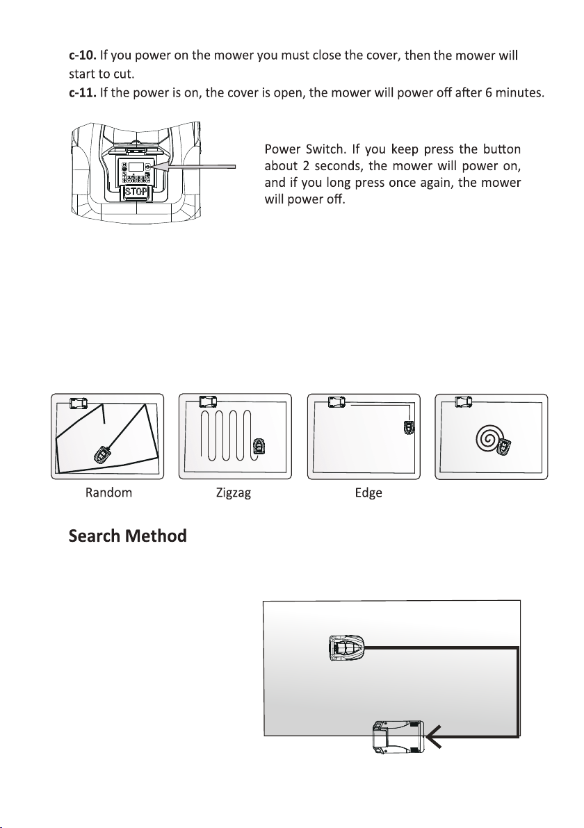
Search Method
Use
Control Panel
Mowing Startpoints
Daily Maintenance
Cleaning
Change The Blades
Winter Storage
Technical Data
03-06
07
07
08
09
09
10-11
12-14
14
14
15-21
21
21-22
23-24
24-31
32
33
33
34
34
34
35
Full Menu Diagram
31

07
1. on your choice of an high quality product. To get
the best from your SØMLØS G1 requires knowledge of its This
Operator's Manual contains important about the mower, how you
install it and how you use it .
2.Read the Operator's Manual carefully and understand the contents before
using your SØMLØS G1.
1. Please read the Operator's Manual carefully and make sure you understand
otherwise it may be damaged if incorrectly
use.
2. It is not to modify the original design of mower. All are
made at your own risk.
3. Check that there are no stones, branches, tools, toys or other on the
lawn that can damage the blades and cause the mower to stop.
4. Never use a high-pressure washer or even running water to clean the mower.
5.
Do not ride or sit on the mower, children and pets should be kept away
from the mower when in
6.
the mower or carry it around when the power is on.
7.
Do not let anyone who does not know how the mower works.
8.
9.
Do not allow the
10. Never put your hands and feet under the mower.
11.
The m
types of wireless systems such as remote controls, radio buried
electric animal fencing or similar.
12.
13.
14. It is forbidden to cut at the lawn with a slope more than 35 degrees.
15.
16.
Carefully read all warnings on th
manual.

08
1.
2.
Carry by the handle at the rear under the mower. Carry the mower
blade plate away from the body.
3.
OK
Correct means Incorrect means
Watch out your hand and feet Read the manual carefully
Don’t ride and sit
Pick up stones, branches,
tools etc. on the lawn
09
1.
cleaning or replacing the blades.
2.
Inspect mower each week and replace any damaged or worn parts, such
as blades.
SØMLØS G1
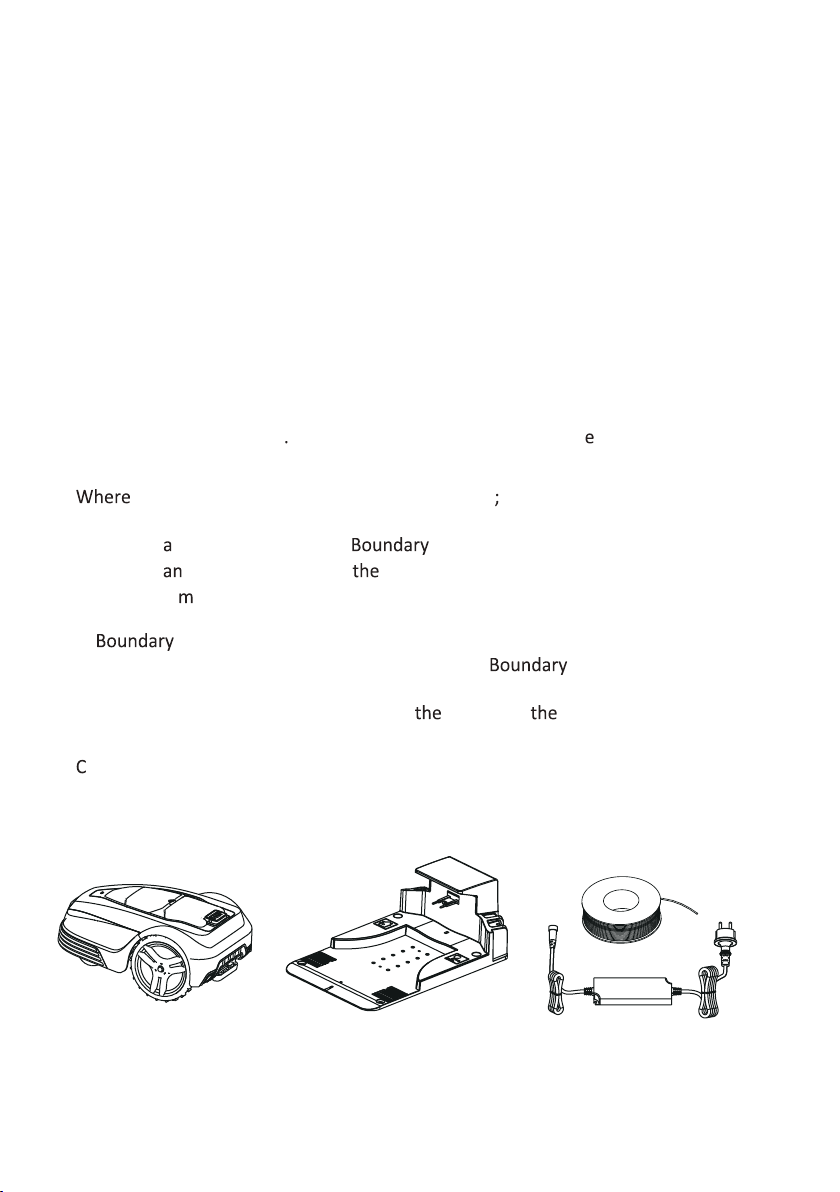
1.
SØMLØS G1;
- The mower is powered by a recharg
2.
a.
To send control-signal to the Wire.
b.
To send avoid-signal around
c.
To charge
3.
Wire
Laid in a loop around mower's working area. The Wire is laid around
the edges of the lawn and around and plants, so the mower will not
run into. The wire is also used for guiding mower to
4.
onnected between the dock and a 100-240V wall socket, the adapter
is connected to the wall socket and to the dock
.
10
1
2
3
4
11
6
7
8
12
13
17
18
19
14
5
9
10
22
23
20
24
21
15
15
14
16

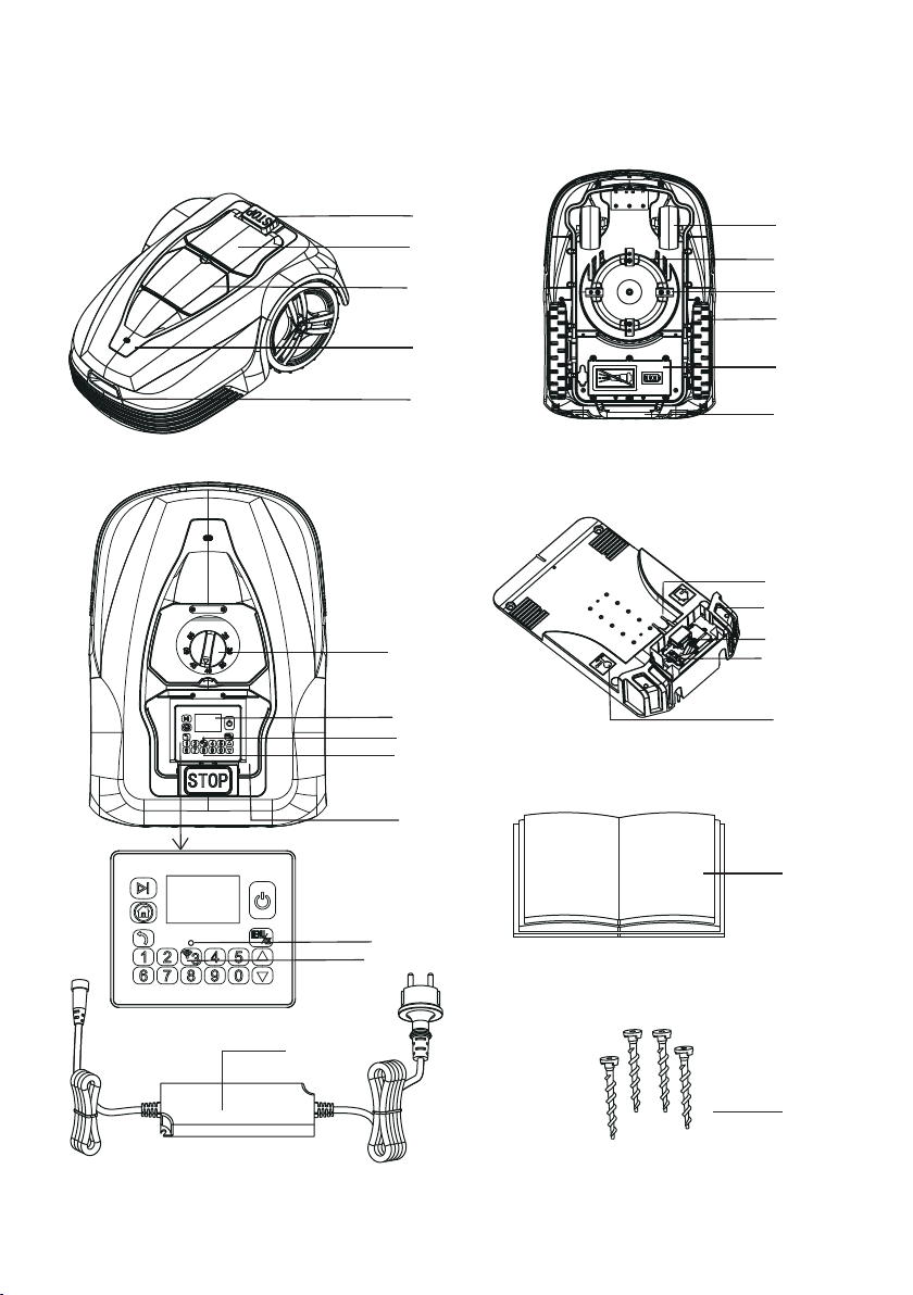
1.
2. The control panel cover
3. Height of cut cover
4. Rain sensor
5. Charging socket
6. Front wheel
7. Blade plate
8. Blade
9. Rear wheel
10.
11. Handle
12.
a nob
13. LCD display
25 26 27
28
14. Wi-Fi indicator light
17.
Charging electrodes
19. Power connector
20. Boundary connector
21.
22. Operator’s manual
23. Power adapter
25.
26.
27. Spare blades
28.
Boundary wire
24.
Pegs for boundary wire
29
29.
Allen wrench
18. Signal indicator light
15.
16. Keyboard

12
G1 is recommended for lawns up to 1000㎡. How large an area is mown
depends on the of the blades and the type of grass, growth rate,
humidity and the shape of the garden. How long the mower runs and
recharges are various due to the ambient temperature. Up to 25°C, fully
charged mower mows for approximately 90 -120 minutes(2.6A
depend
mower is based on an and energy
components. We recommend mainly in dry weather to obtain the best
mowing .
mower should not the d
When there is a risk of a thunder storm, the adapter plug should be removed
from the socket and the Boundary wire disconnected from the d
In order to keep the blades as long as possible, it is important to keep the
mowing and charging.
The charging sends out a signal that mower can sense. starts
to search for the charging when the power s low, which is only
When mower hits an obstacle higher than 6 cm, the mower reverses
carried out in AUTO mode and not MANU mode. Mower does not mow when s

13
When the rain is too heavy, the ower stop work and go to the
If the slope more than 30 degrees, the mower will stop, and the mowing
motor will stop in one sencond.
The STOP in the back of mower is used to stop the mower during its
mowing. When the control panel cover is open, you must clost it to start the mower
again.
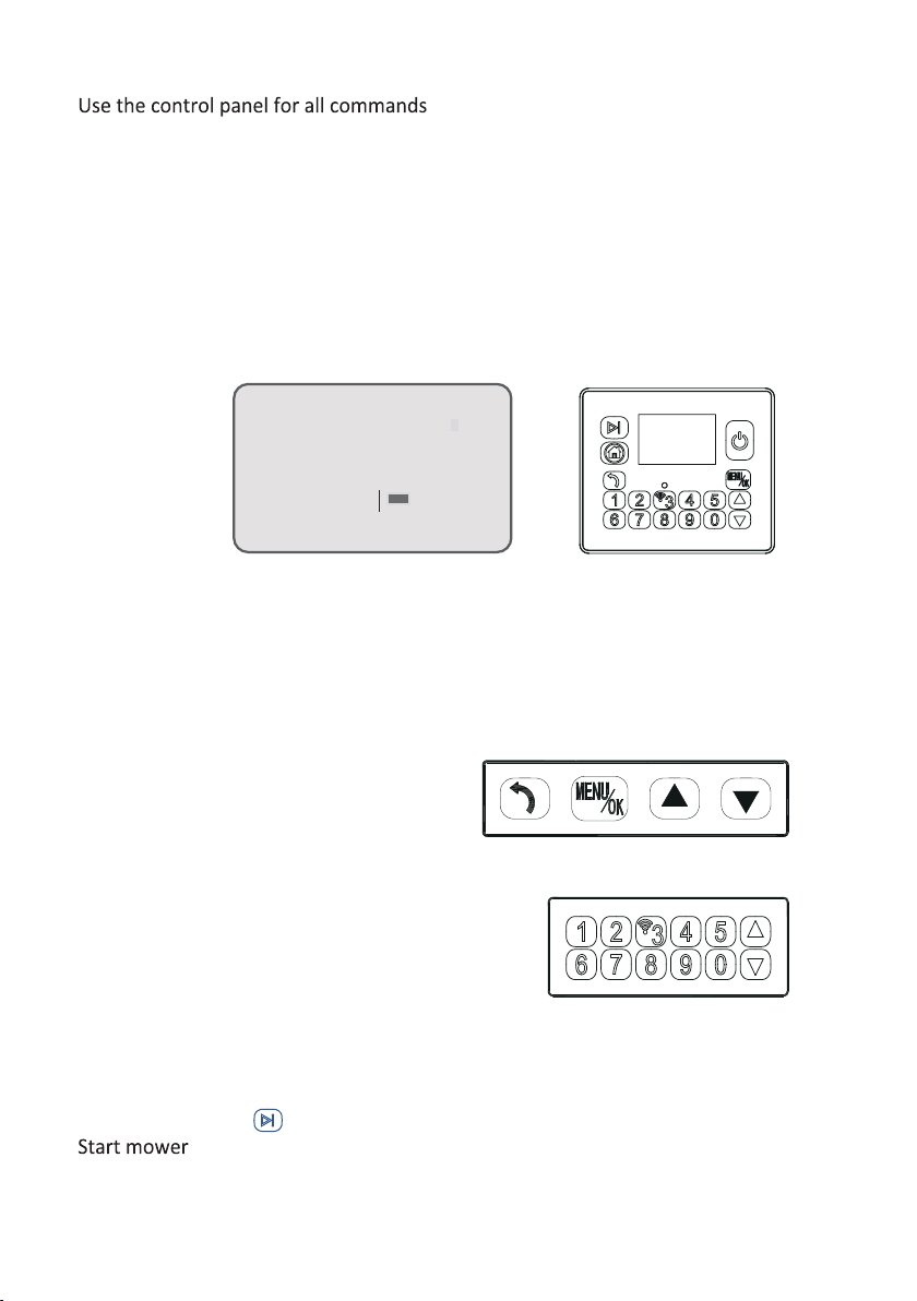
You can manage all the mower program by the control panel under the
control panel cover.
Under the there is a knobrotate clockwise to increase
height and counter-clockwise to reduce .
Mower can not pass Mower can pass Mower can pass ,
but need pick away.
Mower will stop
30
14
If mower enters an area where it senses the grass is high and dense, it will lower the
mowing speed. If the grass become normal, the speed will return to the normal
speed.
obstacles around the boundary wire.
Spiral
13
Read this chapter before
It is important to plan the
Before please make a sketch of the working area, including all
obstacles. This makes it easier to see the ideal for the
boundary wire .
1.
2.
3.
4.
5.
6.
1.
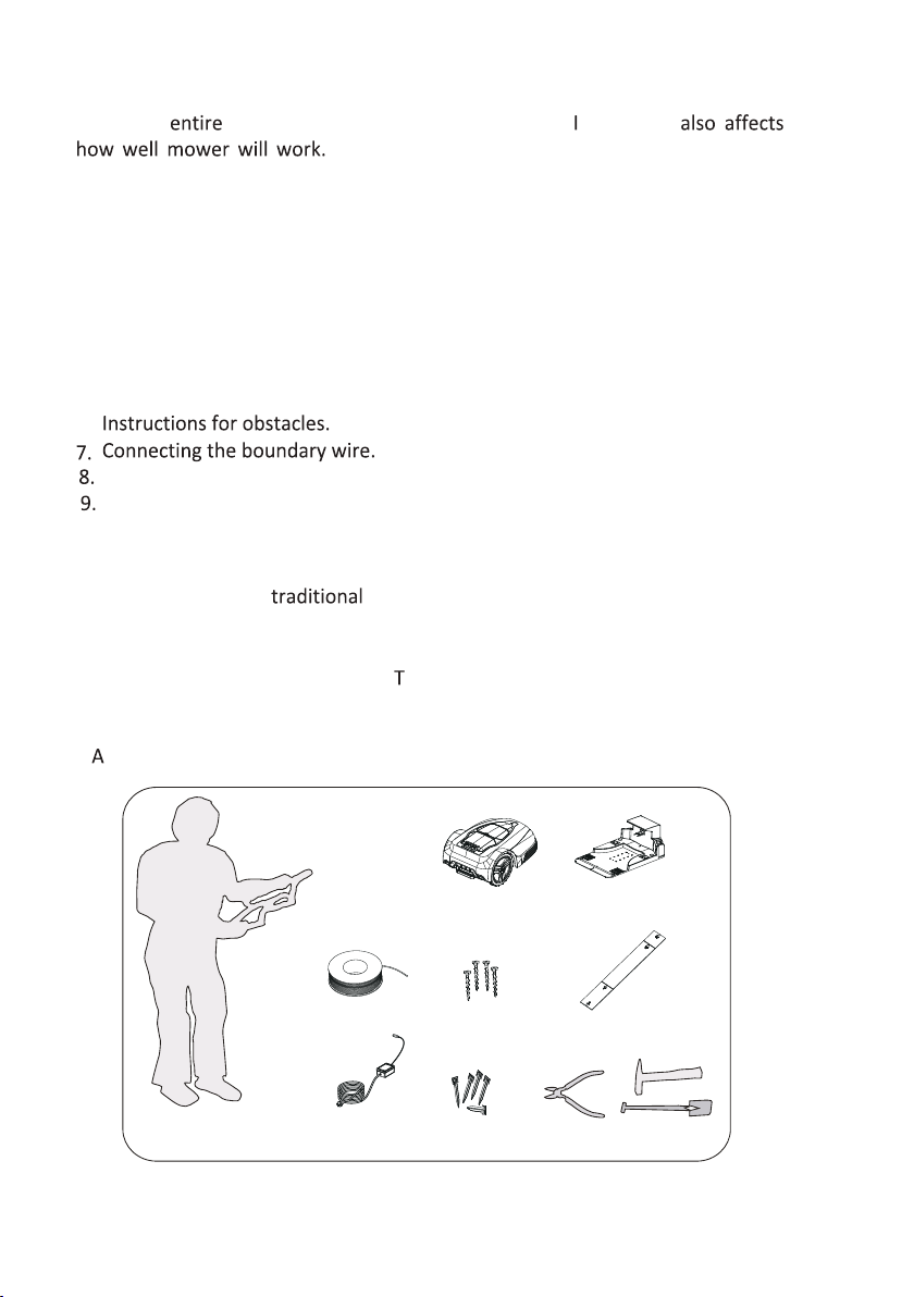
A. If the grass of the lawn in the proposed working area is taller than 10 cm,
please mow it using a lawn mower. Then collect the clippings.
a. Operator's manual b.
G1
c. d.
he boundary wire
e. f . Measurement gauge
g. Adapter h.
Pegs for boundary wire
I. dd -->a pliers for peg , a straight spade for burying wire and a hammer for nails.
abc
e
df
ghI
15
16
2.
a.
b. The
The front end of the
be higher
lower than the back end. The height
c.
if it is charged in the lowest possible ambient temperature.
d.
e.
The low voltage cable may cross the working area. It must be either pegged
, for example, close to a house wall .
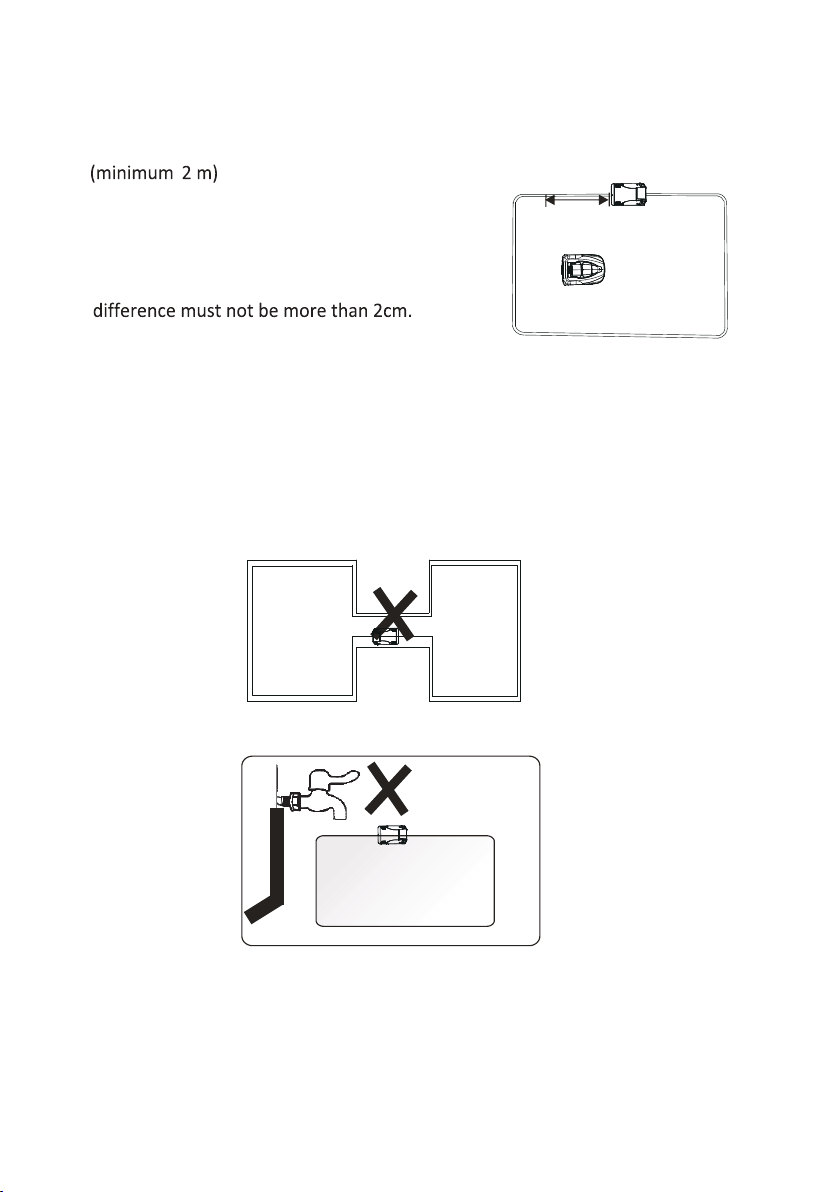
f. Avoid placing the dock in a narrow passage ( narrower than
g.
h.
Avoid the adapter be exposed to direct sunlight.
More than 2m
17
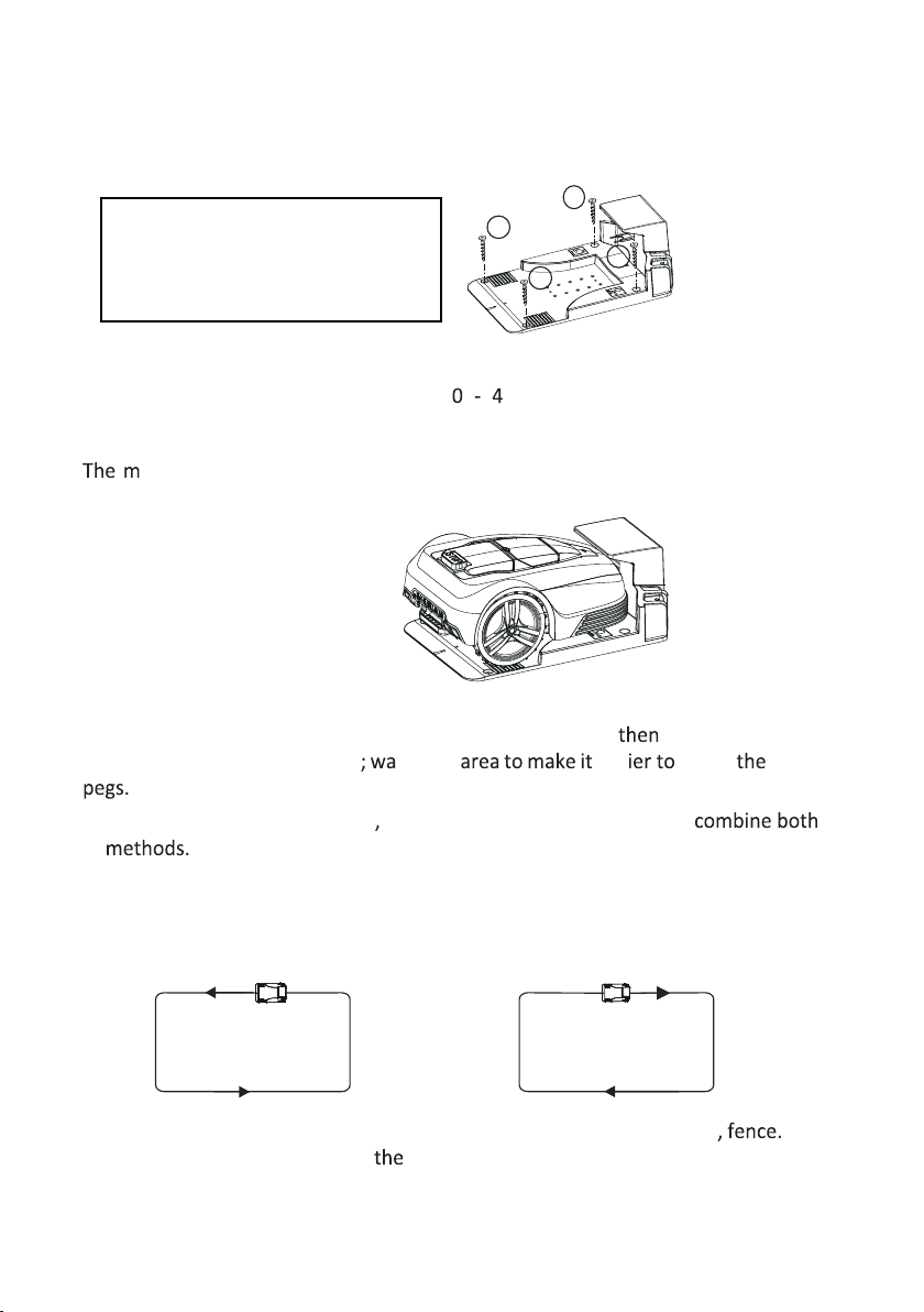
3.
a.
b.
c.
d.
Connect the adapter power cord to a 1 0 2 0V wall socket.
ower is supplied with one or two unfullcharged As soon as the
dock is connected, you can charge the
a.
If you want to the boundary wire in the future it is preferable
to peg down the boundary wire ter the eas insert
b.
If you don’t like to insert pegs you can bury the wire, or you can
c. Laid in a loop around mower’s working area. It is preferable to begin burying wire
from one end of the dock then the boundary wire round the working
d.
The boundary wire should be laid cm from the area edge, obstacle
mower from colliding with the obstacle
and wil reduce mower body wear.
1
2
3
4
From here Start bury From here Start bury
35

18
f.
the
areas must be over
e.
the corners, don’t lay the boundary wire at a sharp or right angle; make sure it
has 35cm space to the wall or other obstacles; a radius at least 50cm
Sharp angle Right angle
Obtuse angle
Arc angle
Cross
Min.35cm
Min.30cm
Min.50cm
Max. 1.5cm
Min.2m
Min.1.2m
Boundary Wire
Min.1.2m
If you have a swimming pool, pls leave 2m between the edge and the limit as a path.
*As below is a general guide line map how to install the mower including placement

19
.
a.
ig trees, poles beds and those can be an obstacle for the mower and
burying the boundary wire.
b.
s should not be mowed, use the boundary wire to protect them.
c.
A big tree with roots that can be an obstacle for the mower should be protected
by burying the boundary wire.
d. Make sure to lay the boundary to the ground. If the boundary wire
is loose or looped on the ground, the mower will cut the wire and the signal
may be not strong enough for the mower to receive.
The lawn mower can detect the signal from the boundary wire within a 20m
radius.
ok
ok
ok
ok
Radius Max. 20m
20
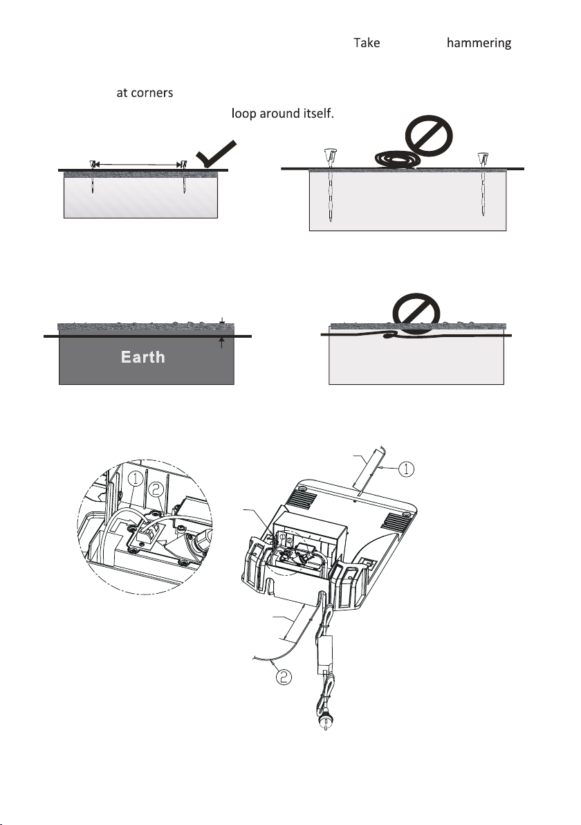
e.
Use a hammer to knock the pegs in the ground. care when
pegs and make sure the wire is on the lawn; the distance between pegs
should be approximately 100cm. The distance between pegs should be
30~50cm .
f.
Don’t let the boundary wire
g. If you intend to bury the boundary wire, make sure to place the boundary wire
between 1mm and 15mm into the ground; the boundary wire should not be
looped under the ground.
7.
Max.15mm
boundary wire
Earth
100cm
Straight Length
>200cm
Straight Length
>30cm
VIEW A
A

21
Open the control panel cover by pressing the STOP
Place
be
If good,
1.
to cut lawn every other day.
2.
1.
2. Press Power switch .
3. Enter the right password.
4.
the start mode.
5.
The mowing is shown on the display, the blades turn and then the
driver wheel will run.
6.
7. Close control panel cover.

22
3.
SØMLØS G1
Preps in one
second, and the control panel cover opens.
.
.
The height can befrom MIN(2.5 MAX(5.5 If the
grass
No.1 Press the STOP
No.2 Push the front cover, and rotate knob
No.3 Rotate knob
No.4 Rotate knob
1. Press the STOP
2.
Long press power switch.
The display is blank.
23
.
via a number of menus.
The control panel consists of a display and a
the display and all input is done on the keypad.
The main menu is the uppermost level of the menu structure.
pressed.
switch.
1.
Press to go back one step in the menu structure, or to interrupt an ongoing input.
2.
Enter values and with the numerical and each selec-
3.
.
Auto
08 July
16:20

24
.
a.
b.
c.
d.
e.
The numbers in brackets refer to the menu rows on the display
number of submenus used to access all to
1.
the
in 24-hour format
24-hour format .
Work Timer A
00:00-00:00
The start time should be
earlier than ending time
Home Auto Man
2. “Work Timer”--->”Work Day”
Use the arrow key to select which day the lawn mower should work.
Use the arrow key to select s* and press yes to set the .
1)
.
convenient and smart use.
Other manuals for G1
1
Table of contents
Other SOMLOS Lawn Mower manuals


Popular Lawn Mower manuals by other brands

Texas A/S
Texas A/S Razor 5105 Series user manual

Jacobsen
Jacobsen AR3 Safety, operation and maintenance manual

American Lawn Mower Co.
American Lawn Mower Co. 1204-14 Operation and assembly instructions

Poulan Pro
Poulan Pro 412412 Operator's manual

Husqvarna
Husqvarna 67522ES owner's manual

Poulan Pro
Poulan Pro PO10530LT Repair parts manual


