Sonexis ConferenceManager User manual
QuickStartGuide
Site Preparation
Installing the Server
Installation Instructions
1
3
• Chooseasitewithpropertemperaturecontroland
adequateoorloadingcapacityforthecurrentinstallation
andforfuturegrowth.InstallnearappropriateACoutlets
andEthernetswitches(10/1000Base-Tcablescannotbe
longerthan100meters).
• Allracksmustbemountedsecurely.Theinstallermust
providetherack-specicinstallationhardware(racknuts,
machinescrews,etc.).
• Leavesufcientclearancearoundtheracktoallowfor
freeairowandforserveraccess.
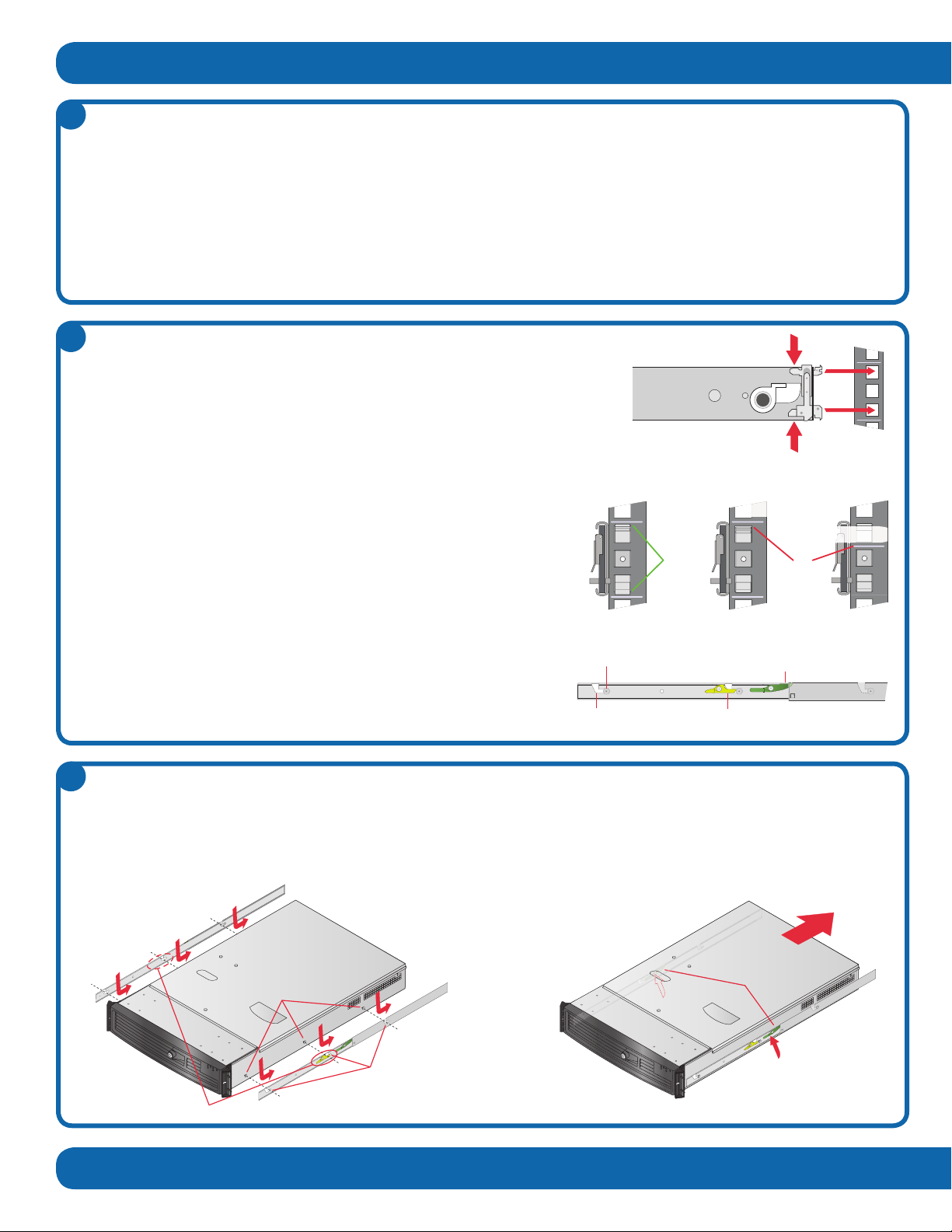
Step1. ExtendeachrailfullyuntiltheSlideExtension
ReleaseLeverslock.
Step2. Positiontheserverovertherailsandalignthesix
mountingpinswiththesixmountingchannels.
• Ifyouareinstallingmultiplesystemsinarack,makesure
theoverallloadingforeachbranchcircuitdoesnotexceed
theratedcapacity.
• Installserversinthelowerpartoftherackbecauseoftheir
weightandtoalloweasieraccesstoservercomponents.
• Donotslidemorethanoneserveroutfromtherackata
time—doingsomaydestabilizetherack.
• Closedoorsandpanelsontherackandservertomaintain
propercoolingwhennotbeingserviced.
Step3. Settheserverdownintotherailsandpushbackuntil
theComponentReleaseLeverslock.
Step4. PresstheSlideExtensionReleaseLeversupwardto
releasethelocksandslidetheserverintotherack.
Installing the Rails
Unpacktheserverandlocatethemountinghardware.
Step1. Findtheverticalpositionintherackwheretherailswillbeinstalled.
Step2. Alignthebackoftheleftsliderailwiththemountingholesontheleftrear
postoftherack.
Step3. Squeezethemountingpinstogetherandinserttherailintotherack.
Step4. Identifythecorrespondingmountingholesontheleftfrontpostoftherack.
Step5. Alignthefrontoftheleftsliderailwiththemountingholes,squeezethemountingpinstogether,andinserttheminto
therack.
Step6. Verifythat:
•Therailislevelfromfronttoback.
•Pinsarefullyseatedintherack.
•Pinsarefullyengagedintheholes.
•Thetoppinisalignedwiththetopofarackunit(orRU,usually
markedwithalineorhole).
Step7. FullyextendthesliderailuntiltheSlideExtensionReleaseLeverlocksintherail’sfullyextendedposition.
Step8. PresstheSlideExtensionReleaseLevertoreleasethelockand
slidetherailinward.Iftherailbindsatanypointalongitsrange
ofmotion,recheckthemountingpositions.
Step9. Repeatsteps1through8withtherightsliderail,makingsure
thattheleftandrightrailsareatthesameheight.
2
Mounting Channels
Mounting Pins
Component Release Levers
Slide Extension
Release Levers
Mounting Channel Component
Release Lever
Mounting Pin
Slide Extension
Release Lever
YesNo
Pins not fully seated
Not aligned with RU
12
3 4
Span 1
Span 2
Span 3
Span 4
T1-2 T1-1
T1-2 T1-1
1
2
S
pan
Sp
an
1
2
S
p
an 3
S
pan 4
T1
-
2
T
1
-
1
T
1
-
2
T
1
-
1
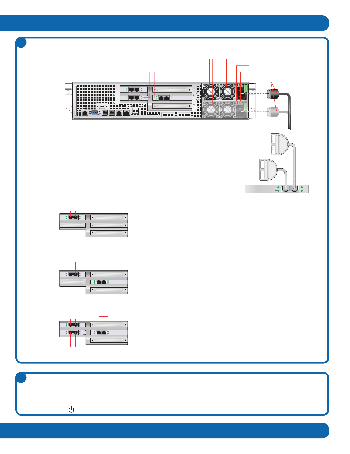
Step1. Connectthepowercord(s)totheconferencingsystemandlocktheminplace.
Step2. ConnecttheEthernetcabletothenetworkinterfaceconnector(LAN1).
ThelicensekeyisassociatedwiththeMACaddressonLAN1.
Step3. ForPSTNsystems,yourconferencingsystemmayhaveone,two,orthreeT1
boards.YouwillreceiveoneT1Splitterforeverytwospans.PlugT1cablesfor
odd-numberedspansintotheT1-1connector,andeven-numberedspansintothe
T1-2connector.
Cabling the System
Afterinstallingtheconferencingsysteminarack,connecttheappropriatepower,network,andT1cables.
Powering the System On
Initialpower-uptakesabouttwominutes.
Topowerthesystemon:
Step1. Connectthepowercord(s).Ifyoursystemhastwopowersupplies,plugthepowercordsintoseparate powercircuits.
Step2. Pressthebuttononthefrontpanel.
4
5
•One-boardsystems:PlugaT1Splitterintotheleftportforspans
1&2;plugasecondT1Splitterintotherightportforspans3&4if
necessary.Connectodd-numberedlinestoT1-1andeven-numbered
linestoT1-2.
•Two-boardsystemslicensedforupto96ports:Connectspans
1through4totheboardinthetop-leftslotasdescribedintheOne-
Board Systemsdiagram.Donotusetheboardintheright-center
slot.
•Two-boardsystemslicensedformorethan96ports:PlugaT1
Splitterintotherightportoftheright-centerslotforspans1&2;
plugasecondT1Splitterintotheleftportoftheright-centerslot
forspans3&4.Connectodd-numberedlinestoT1-1andeven-
numberedlinestoT1-2.
PlugaT1Splitterintotheleftportofthetop-leftslotforspans5&6,
andanotherintotherightportofthetop-leftslotforspans7&8if
necessary.Connectodd-numberedlinestoT1-1andeven-numbered
linestoT1-2.
•Multi-Serversystems:Connectspans1through4totheboardin
thetop-leftslotasdescribedintheOne-Board Systemsdiagram.
PlugaT1Splitterintotheleftportofthebottom-leftslotforspans
5&6,andanotherintotherightportofthebottom-leftslotforspans
7&8ifnecessary.Connectodd-numberedlinestoT1-1andeven-
numberedlinestoT1-2.Donotusetheboardintheright-centerslot.
Spans 1-2 Spans 3-4
Spans 5-6 Spans 7-8
Spans 1-2Spans 3-4
Spans 5-6 Spans 7-8
UnusedSpans 1-2 Spans 3-4
One-Board Systems
Two-Board Systems
Multi-Server Systems
Network Interface Connector (LAN1)
T1 Connectors (1, 2, or 3 Boards)
Power Supply Fans
Power Good Indicators
Power Supply Locks
Power Cords
USB Connectors
Video Connector (Redundant Power Supply Optional)
Network Conguration
• Tograntonlyinternalsystemaccess,congureavalid
internalIPaddressfortheconferencingsystemserver.
Theconferencingsystemwillnotbeaccessibletoexternal
usersexceptviaVPN.
• Tograntexternalsystemaccess,eithercongurean
externalIPaddressandopenTCPport80,orcongure
aprivateIPaddressandNATitthrougharewallto
anexternaladdress.Also,openingTCPports9000+
increasesapplicationsharingperformance.
• YoumaywishtocongureasimpleDNSentryforthe
server,suchasconferencing.example.com.
• TouseSSL,youmustopenTCPport443andinstall
aservercerticate.Youhavemultipleoptionsfor
conguringaudioandwebrewallports.Seethe
Installation and Administration Guideformore
informationaboutSSLandrewallcongurationdetails.
400NetworkCenterDrive
Tewksbury,MA01876
(978)640-2000
www.sonexis.com
SPN11853revA021411
Conguring TCP/IP Settings
Connecting via Another System
IfKVMaccessisnotavailable,youcanlogintotheserver
throughanothersystemusingoneoftwomethods:
• Connecttotheserverthroughahuborswitch.
UsestraightEthernetcablestoconnecttheothersystem
tothehub/switchandthehub/switchtotheserver’s
LAN1port.
• Connectanothersystemdirectlytotheserver.
ConnectanEthernetcrossovercablebetweenthe
LAN1portontheserverandtheEthernetportonthe
othersystem.
Onceconnectedtotheserver,youcanlogintocongureits
TCP/IPsettings:
Step1. CongureyourTCP/IPsettingsasfollows:
IPAddress:192.168.0.2
SubnetMask:255.255.255.0
Step2. Openabrowserandnavigateto
http://192.168.0.125:8097.
Step3. Logintotheconferencingsystemassysadminusing
thepasswordPassword!.
Step4. OpentheNetworkControlPanelandsetthesystem
TCP/IPsettingsasappropriateforyournetwork.
Step5. Reboottheserverifnecessary.
Oncetheconferencingsystemisconguredforyournetwork,
youcanloginthroughabrowserforadditionalconguration.
Afterinstallingtheserver,thenextstepistocongurethe
TCP/IPsettings.Theconferencingsystemshipswithaxed
IPaddress(192.168.0.125),whichyoumustchangeas
appropriateforyournetwork.
Youcanaccesstheconferencingsystemdirectlyby
connectingakeyboard,monitor,andmouse(KVM)tothe
serveritself,orfromanothercomputerusingacrossover
cableorhub.
Connecting via KVM
ToconguretheIntegratedConferenceManagerTCP/IP
settings:
Step1. Plugakeyboard,videomonitor,andmouseinto
thebackoftheconferencingsystem.
Step2. Ifnecessary,reboottheconferencingsystemso
thatitrecognizesthekeyboard,videomonitor,
andmouse.
Step3. Logintotheconferencingsystemassysadmin
usingthepasswordPassword!.
Step4. OpentheNetworkControlPanelandcongure
TCP/IPsettingsforyournetwork.
Step5. Reboottheserverifnecessary.
Onceconguredforyournetwork,youcanlogintothe
conferencingsystemtolicenseitandperformadditional
conguration.Youcanaccesstheadministratorpages
throughawebbrowseroryoumaycontinuetousethe
KVMconnectionsifconvenient.
Disclaimer:ThisQuick Start Guideismeantasageneralguide
toinstallingandconguringtheconferencingsystem.Notevery
congurationorproblemcanbeanticipatedgiventhevariations
inallhardwareandsoftwareproducts.SonexisTechnology,Inc.
acceptsnoresponsibilityforerrorsoromissionscontainedinthis
Guide.
8
6
Licensing the System
TheLicensepagedisplayswhenyourstlogin.Youmust
enteralicensekeytoactivatethefeaturesyoupurchased:
• Single-tenantormulti-tenantsystem
• PSTNorIP-based(H.323,SIP,orTAPI)telephony
• Numberofavailableports(audio,web,orboth)
• Conferencerecording,BlastDial,andMulti-Language
Tolicensetheconferencingsystem:
Step1. Enterthelicensekeyprovidedwithyoursystem.
Step2. ClickApply.
Additional Conferencing Conguration
SeetheInstallation and Administration Guidefordetailson:
• PSTN,H.323,SIP,andVoIPtelephonysettings
• ConguringanSMTPservertosendconferenceinvitations
• Conguringmulti-serverconferencingsystems
TheInstallation and Administration Guideandother
documentationisavailablefromtheHelpbuttononany
conferencingsystemscreen.
7
9
Other Sonexis Server manuals

Popular Server manuals by other brands


Inspur
Inspur NF5266M5 installation guide

HPE
HPE ProLiant DL20 Gen9 Maintenance and service guide

Sun Microsystems
Sun Microsystems Sun Fire X2250 Safety and compliance guide

Supermicro
Supermicro SuperServer SYS-220TP-HTTR user manual

Lenovo
Lenovo ThinkServer TS200 Installation and user guide

Supero
Supero SUPERSERVER 6025B-3 user manual