manuals.online logo
Brands
  1. Home
  2. •
  3. Brands
  4. •
  5. Sonic Frontiers
  6. •
  7. Amplifier
  8. •
  9. Sonic Frontiers SFL-2 User manual

Sonic Frontiers SFL-2 User manual

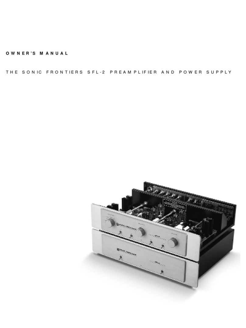
O W N E R ’S M A N U A L
T H E S O N I C F R O N T I E R S S F L - 2 P R E A M P L I F I E R A N D P O W E R S U P P L Y
A - Po w er In p ut Sock et -Plug the Prea
m
plifierPowerCord
(
M
)
fro
m
the Power
S
upply into thissocket.
S
i
m
ply alignthe plug and socketso
the plug insertseasily and freely whenpushing the connectiontogether.
S
crew onlocking ring allowing itto “click”to secure the connection
(
see Figure 1
)
.
B - Se ts 1 & 2 o f th e X
L
R B a l a nce d O u tp uts -These outputsare
balanced and should be used whenconnecting outputsto another
balanced unit.These two outputsallow foreasierbia
m
ping and
greaterflexibility whendealing withco
m
ponentssuchaselectronic
crossovers,etc. Aswithall outputsand inputsonthisPrea
m
plifierthe
leftchannelissituated onthe upperrow ofconnectorsand the right
channelisonthe lowerrow.
C - Se ts 1 & 2 o f t h e RC A Sin g le-En d e d O u t p uts -These unbal-
anced outputsare single ended and should be used whenconnecting
the outputsto anothersingle-ended unit.These two outputs,aswiththe
X
L
R
outputs
(
B
)
,allow foreasierbia
m
ping and greatersyste
m
flexibility.
D - RC A Si ngl e-En d e d Ta p e O utp ut -These outputsconnectto the
inputsofa tape deck.Whennotrecording these outputsshould be
m
uted via the
R
ecord / Off
S
witch
(
O
)
.
E - RCA Si n gle-En d ed A u x ilia r y In p ut -Thisinputwill accepta
single-ended inputconnectionfro
m
a high-levelsource suchasa
VC
R
ora step-up device fora
m
oving coilor
m
oving
m
agnetphono
cartridge suchasour
S
FP-1or
S
FP-1
S
ignature Phono
S
tage.
F - RC A Si n g le-En d e d T a p e In pu t -Thisinputacceptsa single-
ended inputconnectionfro
m
a tape source.
G - RC A Si ngle-En d e d Tun e r In p ut -Thisinputacceptsa single-
ended inputconnectionfro
m
a tunersource.
H - RC A Si n gl e-En d e d Co m p a ct DiscIn p ut -Thisinputacceptsa
single-ended inputconnectionfro
m
a co
m
pactdiscplayerora digital
-to-analog processorsuchasour
S
FD-1 or
S
FD-2.
I- Direct RCA Si n gle-En d e d In p ut -Thisinputacceptsa single-
ended inputconnectionfro
m
any source to achieve the highestpossi-
ble sonicperfor
m
ance,bypassing the Balance Control
(
Q
)
and the
R
ecord / O ff
S
witch
(
O
)
.
J - Direct X
L
R B a la nce d In p u t -Thisinputacceptsa balanced
inputconnectionfro
m
any source to achieve the highestpossible sonic
perfor
m
ance,bypassing the Balance Control
(
Q
)
and the
R
ecord / Off
S
witch
(
O
)
.
K - D et a ch a ble Po w er Co rd Sock et -Plug the Power
S
upply’s
Detachable PowerCord into thissocket
(
see Figure 2
)
.The
S
F
L
-2 is
factory setforthe correctoperating voltage forthe area inwhichitis
sold
(
see shipping box forvoltage setting
)
.Ifa differentoperating volt-
age isrequired,please contactanauthorized
S
onicFrontiersdealer,
distributororthe factory directly.
L - A C
L
in e Fuses -These are the leftand rightchannelA C fuses.They
m
ay be accessed witha s
m
all slotscrewdriverby turning a 1/ 2 turn
counterclockwise to unlocka spring thatejectsthe fuse holdersout.
The unitisfactory installed with“fast-blo”1.5 A
m
p 250V
(
0.25”x
1.25”
)
or0.75 A
m
p 250V
(
0.25”x 1.25”
)
forEuropean
and Asianversions.
M
-P o w e r Su p p ly U m bilical Co r d -ThisU
m
bilicalCord exitsthe
Power
S
upply to plug into the PowerInput
S
ocket
(
A
)
onthe
S
F
L
-2
Prea
m
plifier
(
see Figure 1 forconnection
)
.Itdoesnotdisconnectfrom
thePower Supply.
A B C D E F G H I J
K L M
O P E R A T I O N , C O N N E C T I O N S A N D C O N T R O L F U N C T I O N S
U V W X
N O P Q R S T
N - Se lecto r S w itch-Thisknob isturned to selectaninput
(
E
)
through
(
J
)
.
O - Re cor d / O ff S w itch-Thistoggle switchturnsthe outputsoff and
preventsthe
m
ainprea
m
p outputsfro
m
being loaded downby the
non-linearload of
m
osttape deckswhenthe record functionsare not
inuse.To record,
m
ove the switchto the record positionand waita
shortdelay
(
5 seconds
)
forthe protective
m
uting functionto clearand
connectthe tape outputs.
P - 1 80°/ 0°S w itch-Thistoggle switchallowsthe userto invertthe
syste
m
phasing easily and safely.Depending uponthe
m
ethodsused
inproducing the recording,the user
m
ay preferlistening to a given
recording ineitherphase position-letyourearsbe yourguide.
Q - B a l a n ce C ontro l -Thisknob controlsthe relative balance ofthe left
and rightchannelsto co
m
pensate forany discrepanciescaused by
speakerplace
m
ent,source i
m
balance,etc.
R - M ut e / O p e r a te S w itch -Inthe
m
ute position,thistoggle switch
cutsoff the signalto the
S
F
L
-2 outputs
(
Band C
)
; the
L
ED
(
W
)
flashesas
a re
m
inder.Inthe operate
m
ode,the outputsare connected.
S - -1. 5 d B / 0 dB S w itch -Thistoggle allowsforgreatervolu
m
e
controloverthe 23-step / 3 dB perstep Volu
m
e Attenuator
(
T
)
.Inthe
-1.5 dB positionthe volu
m
e levelwill be reduced by 1.5 dB.Thisfea-
ture providesthe attenuatorwitha totalof46 discrete steps,allowing
the usera wide,precise volu
m
e controlrange.
T - 2 3-Ste p Pr ecisio n B a l a nce d V o lu m e Att en u a t or C o ntr ol -
Thisknob controlsthe balanced attenuator.The attenuatoris
m
anufac-
tured witha ladderofprecision
m
etalfil
m
resistorsthatgive precise
controloverleftand rightchannellevelsin3 dB stepsover23 posi-
tions.Turnitclockwise and the
m
usicgetslouder!
U - O p e r a t e / St a n d b y S w i tch -Whenthistoggle switchisinthe
operate positionand the Power
S
upply
S
witch
(
X
)
ison,the
Prea
m
plifierisfully functional.Inthe standby “resting”
m
ode,poweris
still supplied to the tube fila
m
ents,butthe highvoltage powersupplies
are disconnected fro
m
the audio circuitry.
V -
L
ED P o w e r S u p p l y -This
L
ED lightswhenthe Power
S
upply ison.
W
-
L
ED Pre a m plifi er
-This
L
ED lightswhenthe Prea
m
plifierison
and flashesduring war
m
up,
m
uting,orlow voltage fro
m
the A.C.
powersource.
X - O n / O f f S w itch -Inthe “on”position,thistoggle turnsthe
Power
S
upply on.Inthe “off”position,the Power
S
upply and
Prea
m
plifierare off.
Note: Be surethePower Supply Umbilical Cord
(
M
)
thatisattached
to thePower Supply chassisisplugged into thePreamplifier chassis
beforetheOn/ Off Switch
(
X
)
isturned on.Failureto do thismay
causedamageto theSF
L
-2.
Top view oftubesocketorder
(
Front
(
faceplate
)
oftheSF
L
-2
)
Fig u re 3 -Tube and tube socketorder.
Figu re 4 -Tube pinalign
m
entwiththe socket.
N ote th e l a rg er s p ace
b e tw e e n t w o o f th e p ins a n d
h oles for p r o p e r a lig n m e nt
of tu b e a n d sock et.
W A R N I N G
DO N OTADJUSTthe controlsrepresented inthe shaded box
showninFigure 3 below.These controlshave beenfactory set
forthe opti
m
u
m
perfor
m
ance
(
bothsonically and electrically
)
of
the
S
F
L
-2 Prea
m
plifier.Do notadjustthese controls-doing so
will degradethe perfor
m
ance ofthe
S
F
L
-2.They
m
ay only be
adjusted using specialized testequip
m
entthatonly authorized
service depots,distributorsorthe
S
onicFrontiersfactory have
forthispurpose.
Fi g u r e 2 -Alignsocketpinsto corresponding holesand pushtogether.
Fig u re 1 -Alignpinsinreceptacle
(
A
)
to pinholesinconnector
(
M
)
,
alignnotchesto ridgesand pushtogether.Turnlocking ring clockwise until
it“clicks”indicating itislocked.
AM
W A R N I N G
DISC O N NECTthe AC Detachable PowerCord fro
m
the
S
F
L
-2 Power
S
upply beforere
m
oving the Prea
m
plifier
chassiscover.
I N S E R T I O N O F T H E T U B E S
The
S
F
L
-2 co
m
eswitheight6 9 2 2
(
6D
J
8-type
)
tubes,individual-
ly boxed and bagged along witha cottonglove,allenkey,
PearlTM Tube C oolersand screwsforfastening the
S
F
L
-2 cover.
Please re ad and follow these instructionscarefully.Greatcare
wastakeninthe testing,selectionand
m
atching ofthe supplied
tubesinorderto ensure properoperationofthe unit.Failure to
follo w these instructionswill cause the
S
F
L
-2 Prea
m
plifierto
sufferinperfor
m
ance and sound quality.
1.Be surethatthe AC Detachable PowerCord isdisconnected
fro
m
the
S
F
L
-2 Power
S
upply beforere
m
oving the Prea
m
plifier
chassiscover.
2.Using the allenkey,re
m
ove the coverofthe
S
F
L
-2
Prea
m
plifier.Forconvenience,there will be only two screws
holding itinplace.
3.Whenhandling the tubes,itisreco
mm
ended the cotton
glovesprovided be wornto preventskinoilsfro
m
depositing
onthe glass surface and possibly causing the tube to beco
m
e
pre
m
aturely “gassy”,thereby shortening the tube’susefuloper-
ating life.
4.Inspectthe tubesforcode
m
arkings.They will be coded
individually,eachwithone ofthe following codes:
L
V1 ,
L
V2,
L
V3,
L
V4 ,V 1,V2,V3 and V4.
5.Inspectthe tube socketsinthe
S
F
L
-2 Prea
m
plifierforthe
codes
m
atching the codesonthe tubes.The coding isprinted
onthe PCB circuitboard beside the tube sockets.
S
ee Figure 3
forfurtherclarification.
6.Take the
L
V1 tube and inspectthe pinsnoting the larger
space betweentwo ofthe pins.Thisspace will alignwiththe
sa
m
e largerspace betweentwo ofthe pinholesonthe socket.
Insertthe
L
V1 tube into the
L
V1 tube socket,
m
aking sure all
pinsand pinholesare aligned
(
see Figure 4
)
.Do notforce the
tube into the socket.
R
ockthe tube gently while pushing slowly
untilthe tube isfir
m
ly seated.
R
epeatthisstep forthe re
m
aining
tubes,
L
V2 tube to the
L
V2 tube socket,
L
V3 tube to the
L
V3
tube socket,
L
V4 tube to the
L
V4 tube socket,V1 tube to the V1
tube socket,V2 tube to the V2 tube socket,V3 tube to the V3
tube socketand V4 tube to the V4 tube socket.
7.Install the supplied PearlTM Tube coolersovereachtube,
keeping the botto
m
edge ofthe coolera way fro
m
the top sur-
face ofthe socket.N ext,install the supplied rubber“O”-rings-
2 ringspercooler,evenly spaced at1 / 3 fro
m
the botto
m
and
1 / 3 fro
m
the top to cla
m
p the coolerfir
m
ly around the tube.
8.
R
eplace the coverand fastenitwiththe screwsprovided.
The
S
F
L
-2 Prea
m
plifierisnow ready foroperation.
R E P L A C E M E N T O F T H E T U B E S
S
onicFrontiersstrongly discouragesnon-factory replace
m
entof
the tubes.The eight69 2 2
(
6D
J
8-type
)
tubesare
m
easured,
selected,and
m
atched inbalanced pairs-channelto channel
and triode sectionto triode section-foropti
m
u
m
perfor
m
ance.
Ifreplace
m
enttubesare needed ordesired,contact
S
onic
Frontiersforassistance.
S F L - 2 P R E A M P L I F I E R A N D
P O W E R S U P P L Y P L A C E M E N T
Underno circu
m
stance should the
S
F
L
-2 Power
S
upply be
placed directly ontop ofthe
S
F
L
-2 Prea
m
plifier.Thiswill not
allow adequate ventilation,and overheating will result.
The units
m
ay be stacked ifthe Prea
m
plifierissituated ontop
ofthe Power
S
upply.A betterarrange
m
entwould be to place
the unitsside by side oronseparate shelvesand free fro
m
obstructionwhich
m
ay inhibitadequate ventilation.
Allow atleast6”
(
1 5 c
m
)
ofclearspace above the
Prea
m
plifierchassisforproperventilation.
T R O U B L E S H O O T I N G
Ifthe
S
F
L
-2 Prea
m
plifierisnotproducing sound,please check
eachofthe following:
1.Checkthatthe AC Detachable PowerCord isplugged into
the
S
F
L
-2 Power
S
upply’sDetachable PowerCord
S
ocket
(
K
)
and isconnected to a livesource ofA C power.Forinstance,if
using a powerbar,checkthatthe baristurned on.
2.Be sure thatthe O perate /
S
tandby
S
witch
(
U
)
onthe Power
S
upply chassisisinthe “up”
(
operate
)
position.
3.Checkthatthe proper inputhasbeenselected withthe
S
elector
S
witch
(
N
)
onthe Prea
m
plifierchassis.
4.Ensure thatthe Mute / O perate
S
witch
(
R
)
isinthe “down”
(
operate
)
position.
5.Checkthatboth A C
L
ine Fuses
(
L
)
atthe rearofthe Power
S
upply chassisare good.Be sure tofirstunplug the A C
Detachable PowerCord fro
m
the Power
S
upply.
6.Checkto be sure thatall eight6 92 2 tubesare correctly and
fir
m
ly seated intheirtube socketsand thatall nine contactpins
are inserted ineachsocket
(
i.e.no pinsare bentover
)
.Verify
thatanorange glow isvisible fro
m
inside ofeachtube when
the unitison.
7.Ifyouare still experiencing any difficulty withyour
S
F
L
-2
Prea
m
plifier,contactyourde alerordistributorforassistance.
S A F E T Y I N S T R U C T I O N S
1.Ventilation-Althoughyour
S
F
L
-2 Prea
m
plifiergeneratesonly
no
m
inalheatinuse,be sure thatthe ventilationslotsinthe top
coverhave atleast6”ofunobstructed airspace above the
m
.
2.W aterand Moisture -Thisproductshould notbe used near
water.Do notexpose thisproductto rainor
m
oisture to prevent
fire orshockhazard.
3.Heat-Thisproductshould be situated aw ay fro
m
heat
sourcessuchasradiators,heatregisters,stoves,orotherappli-
anceswhichproduce heat.
4.Power
S
ources-Thisproductshould be connected to anA C
powersource ofthe properrated voltage.The originalship-
ping containerswill stipulate the A C voltage thisunitcanoper-
ate withcorrectly.
5.Cleaning -A regulardusting witha soft,non-abrasive cloth
will generally keep the finishofthe faceplate and chassislook-
ing like new.Atno ti
m
e should youallow any liquid to co
m
e in
contactwiththe
S
F
L
-2 Prea
m
plifierand Power
S
upply; it
m
ay
runinto the electroniccircuitry and cause d a
m
age whichwill
notbe covered underyourw arranty.
6.
S
ervicing -Do notopenthisproduct.No user serviceable
partsinside.
R
eferservicing to anauthorized service technician.
7.Non-Use Periods-The powercord ofthisproductshould be
unplugged fro
m
the outletwhenleftunused foranextended
period ofti
m
e.
8.Do notre
m
ove Prea
m
plifierorPower
S
upply coverswhile
unitis“on”,in“standby”orconnected to anA C powersource.
Coverscrewscould fall throughventilationslotswhich
m
ay
cause da
m
age
(
electricalshorts
)
to the
S
F
L
-2.
P A C K I N G M A T E R I A L S
W e reco
mm
end thatyouretainall ofthe p acking
m
aterialand
shipping boxesforyour
S
F
L
-2 Prea
m
plifierand Power
S
upply.
They are custo
m
designed to preventshipping da
m
age fro
m
occurring.
S
onicFrontiers,Inc. will acceptno responsibility for
any da
m
age occurring to an
S
F
L
-2 Prea
m
plifierand Power
S
upply thatisshipped inpacking
m
aterialotherthanthe origi-
nal
S
onicFrontiersp acking
m
aterial.
D I S C L A I M E R O F L I A B I L I T Y
Underno circu
m
stancesdoes
S
onicFrontiers,Inc. assu
m
e lia-
bility orresponsibility forinjury orda
m
agessustained inthe use
oroperationofthisequip
m
entorforda
m
agesto any other
equip
m
entconnected to it.
S
onicFrontiers,Inc. reservesthe rightto
m
ake designchanges
ori
m
prove
m
entswithoutthe obligationto revise priorversions.
All specificationsare subjectto change withoutnotice.
L I M I T E D F I V E Y E A R W A R R A N T Y
S
onicFrontiers,Inc. warrantsto the purchaserthateach
S
F
L
-2
Prea
m
plifierand Power
S
upply isfree of
m
anufacturing defects
fora period offive
(
5
)
yearsfro
m
the date ofpurchase.This
five
(
5
)
yearli
m
ited non-transferable warranty excludesall vacu-
u
m
tubes,whichwe w arrantfora period oftwelve
(
1 2
)
m
onths.To receive thiswarranty,the originalpurchaser
m
ust
co
m
plete and
m
ailto
S
onicFrontiers,withinthirty
(
3 0
)
days
fro
m
the date ofpurchase,the enclosed W arranty
R
egistration
For
m
.
S
onicFrontiers,Inc. will thenvalidate the warranty to the
originalpurchaser.Thisw arranty issubjectto the following
conditionsand li
m
itations:
1
.W arranty appliesonly to the originalpurchaser.
2.Thiswarranty isvoid and inapplicable ifthe producthas
beenhandled otherthaninaccordance withthe instructionsin
thisO wner’sM anual,abused or
m
isused,da
m
aged by acci-
dentorneglectorinbeing transported,orthe defectisdue to
the productbeing ta
m
pered with,
m
odified orrepaired by any-
one otherthan
S
onicFrontiers,Inc. oranauthorized
S
onic
Frontiersrepairdepot.
3.W arranty doesnotcovernor
m
al
m
aintenance.
4.
S
onicFrontiers,Inc. shall notbe responsible inany way for
consequentialorindirectda
m
agesorliabilitiesresulting fro
m
the use and operationofthe productcovered hereinorresult-
ing fro
m
any breachofthiswarranty orany i
m
plied warranty
relating to said product.
During thisperiod,
S
onicFrontiers,Inc. will repairorreplace
any defective co
m
ponentsfree ofcharge.A
R
eturnAuthoriza-
tionNu
m
ber
(
R
A N
)
isrequired before any productisreturned
to ourfactory forany re ason.Thisnu
m
ber
m
ustbe visible on
the exteriorofthe shipping container
(
s
)
for
S
onicFrontiersto
acceptthe return.
Unitsshipped to uswithouta
R
eturnAuthorizationN u
m
beror
withouta visible
R
A N onthe exteriorofthe shipping contain-
er
(
s
)
will be returned to the sender,freightcollect.
Unitsto be repaired by
S
onicFrontiers,Inc.
m
ustbe sentship-
ping and insurance prepaid by the originalpurchaserinthe
originalpacking
m
aterial.A returned productshould be acco
m
-
panied by a writtendescriptionofthe defect.
R
epaired units
will be returned by
S
onicFrontiers,Inc. shipping and insurance
prepaid.
All otherwarrantiesorconditionseitherwrittenori
m
plied
are void.
Note: Inforeign
m
arkets
(
anywhere outside ofC anada and the
U
S
A
)
,the warranty issupplied by the authorized International
Distributor.Exactter
m
sand conditions
m
ay vary.
T E C H N I C A L S P E C I F I C A T I O N S
Frequency
R
esponse 2 Hz to 100 kHz
±
0.5 dB
(
100K load
)
> 3 5 0 kHz -3.0 dB
THD &N < 0.1%fro
m
20 Hz to 20 kHz
(
@ 1 V output
)
typically < 0.03%@ 1 kHz
G ain22 dB @ 1 kHz
(
single-ended
)
28 dB @ 1 kHz
(
balanced
)
Noise 120 uV unweighted
(
balanced outputs,
volu
m
e control@ 12 o’clock
)
-85 dB below @ 2 Volt
R
.M.
S
.output
S
MPTE
(
IMD
)
< 0.05%,typically 0.03%
(
balanced
)
@ 2 V output
InputI
m
pedance 50 K oh
m
s
(
single-ended
)
100 K oh
m
s
(
balanced
)
OutputI
m
pedance 160 oh
m
s@ 1 kHz
(
single-ended
)
320 oh
m
s@ 1 kHz
(
balanced
)
Mini
m
u
m
R
eco
mm
ended
L
oad I
m
pedance 10 K oh
m
s
OutputVoltage Maxi
m
u
m
30 V
R
.M.
S
.
(
single-ended
)
(
100K / 100pf&Maxi
m
u
m
60 V
R
.M.
S
.
(
balanced
)
10K / 1000pfloads
)
Maxi
m
u
m
Input
2.5 V
R
.M.
S
.
(
Volu
m
e controlfully clockwise
)
S
tereo
S
eparation70 dB @ 1 kHz
(
single-ended
)
(
Crosstalk
)
75 dB @ 1 kHz
(
balanced
)
Power
R
equire
m
ents
135 VA
(
75 VA instandby
m
ode
)
50 / 60 Hz
1.1 A
m
ps@ 120 V A.C.
Fuse
R
equire
m
ents
(
2
)
1.5 A
m
p 250 V fast-blo
(
100 V to 1 20 V Countries
)
0.75 A
m
p 250 V fast-blo
(
200 V to 2 40 V Countries
)
Tube Co
m
ple
m
ent8 -6922
(
6D
J
8 types
)
Di
m
ensions19”W ide x 13”Deep x 4.5”High
(
eachchassis
) (
48 c
m
x 33 c
m
x 11.5 c
m
)
W eight55 lbs
(
25 kg
)
-unpacked
62 lbs
(
28 kg
)
-factory packed
N OTE: All
m
easure
m
entsperfor
m
ed withanAudio Precision
S
yste
m
One testcenter.
Thissy
m
bolisintended to alertthe
userto the presence ofuninsulated
“dangerousvoltage”withinthe
product’senclosure that
m
ay be of
sufficient
m
agnitude to constitute
a riskofelectricshockto persons.
Thissy
m
bolisintended to alertthe
userto the presence ofi
m
portant
operating and
m
aintenance
(
servicing
)
instructionsinthe literature acco
m
pany-
ing the appliance.
W e at
S
onicFrontiersare sure thatyouwill derive
m
any yearsof
listening pleasure withyournew
S
F
L
-2 Prea
m
plifierand Power
S
upply.ThisO wner’sM anualcontainsi
m
portantinfor
m
ation
regarding the operationand care ofthe
S
F
L
-2.Be sure to read
this
m
anualcarefully and follow these instructionsinorderto
keep itlooking,operating and sounding itsbest.
2 7 9 0 Brighton
R
oad,O akville,Ontario,C anada,
L
6H 5T4 Telephone:
(
9 0 5
)
8 2 9 -3 83 8 Facsi
m
ile:
(
905
)
8 2 9 -30 3 3
S
onicFrontierscanbe re a ched fro
m
9 : 0 0 a .
m
.to 5 : 0 0 p .
m
., Eastern
S
tand ard Ti
m
e,or2 4 hoursa day by facsi
m
ile.

Other Sonic Frontiers Amplifier manuals

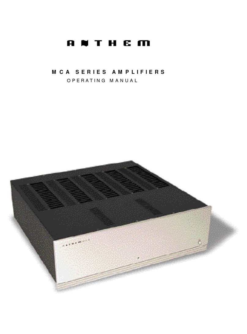
Sonic Frontiers MCA Series User manual

Sonic Frontiers

Sonic Frontiers MCA Series User manual

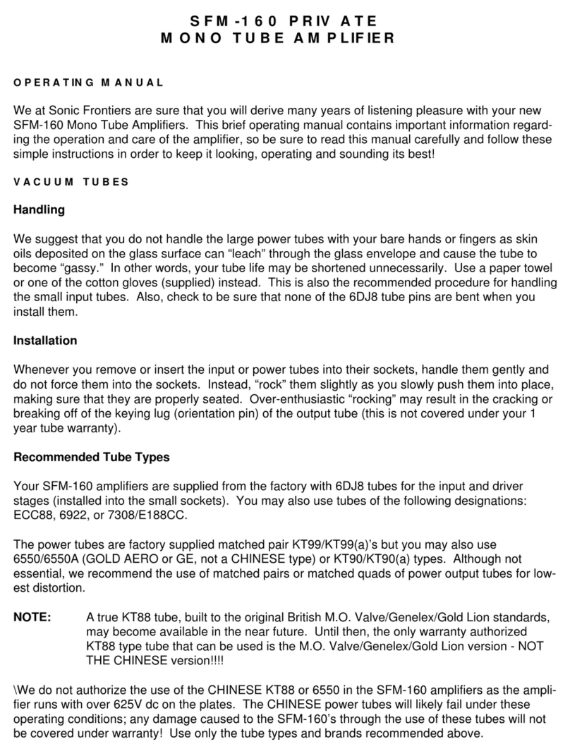
Sonic Frontiers Sonic Frontiers SFM-160 PRIVATE User manual

Sonic Frontiers

Sonic Frontiers Sonic Frontiers SFM-160 PRIVATE User manual

Sonic Frontiers SONIC FRONTIERS SFC-1 User manual

Sonic Frontiers

Sonic Frontiers SONIC FRONTIERS SFC-1 User manual

Sonic Frontiers Anthem STATEMENT P2 User manual

Sonic Frontiers

Sonic Frontiers Anthem STATEMENT P2 User manual

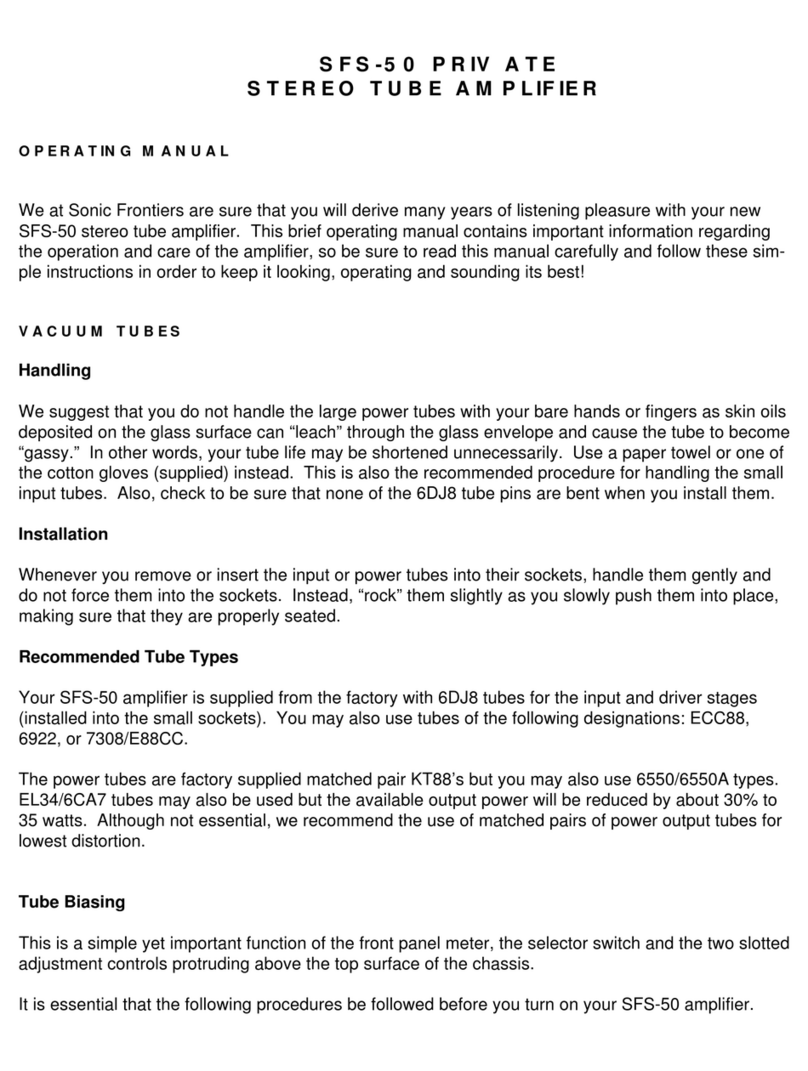
Sonic Frontiers Sonic Frontiers SFS-50 PRIVATE User manual

Sonic Frontiers

Sonic Frontiers Sonic Frontiers SFS-50 PRIVATE User manual

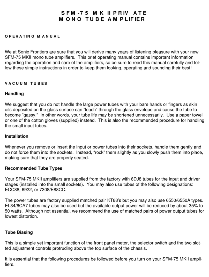
Sonic Frontiers Sonic Frontiers SFM-75 MK-II User manual

Sonic Frontiers

Sonic Frontiers Sonic Frontiers SFM-75 MK-II User manual

Sonic Frontiers Sonic Frontiers SFL-2 User manual

Sonic Frontiers

Sonic Frontiers Sonic Frontiers SFL-2 User manual

Sonic Frontiers Sonic Frontiers Power 1 User manual

Sonic Frontiers

Sonic Frontiers Sonic Frontiers Power 1 User manual

Sonic Frontiers Sonic Frontiers SFS-80 User manual

Sonic Frontiers

Sonic Frontiers Sonic Frontiers SFS-80 User manual

Sonic Frontiers THE SONIC FRONTIERS LINE SERIES User manual

Sonic Frontiers

Sonic Frontiers THE SONIC FRONTIERS LINE SERIES User manual

Sonic Frontiers Power 2 User manual

Sonic Frontiers

Sonic Frontiers Power 2 User manual

Sonic Frontiers Sonic Frontiers SFL-1 User manual

Sonic Frontiers

Sonic Frontiers Sonic Frontiers SFL-1 User manual

Sonic Frontiers SFP-1 SIGNATURE User manual

Sonic Frontiers

Sonic Frontiers SFP-1 SIGNATURE User manual

Sonic Frontiers SONIC FRONTIERS Processor 3 User manual

Sonic Frontiers

Sonic Frontiers SONIC FRONTIERS Processor 3 User manual

Sonic Frontiers Sonic Frontiers SFS-40 User manual

Sonic Frontiers

Sonic Frontiers Sonic Frontiers SFS-40 User manual

Sonic Frontiers Sonic Frontiers PHONO 1 User manual

Sonic Frontiers

Sonic Frontiers Sonic Frontiers PHONO 1 User manual

Popular Amplifier manuals by other brands

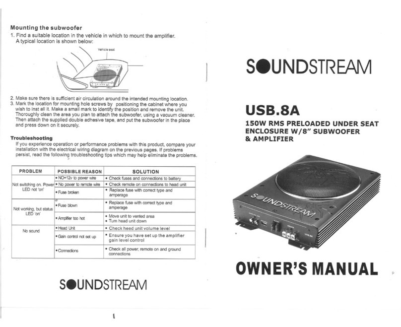
Soundstream USB.8A owner's manual

Soundstream

Soundstream USB.8A owner's manual

Jensen A1000 Owner's manual and installation instructions

Jensen

Jensen A1000 Owner's manual and installation instructions

Violectric HPA V550 Short form manual

Violectric

Violectric HPA V550 Short form manual

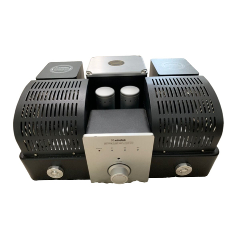
XINDAK V10 instructions

XINDAK

XINDAK V10 instructions

Matrix Amplification GM50 user manual

Matrix Amplification

Matrix Amplification GM50 user manual

Yamaha YST-A5 owner's manual

Yamaha

Yamaha YST-A5 owner's manual

Ashly pema operating manual

Ashly

Ashly pema operating manual

McIntosh Power Amplifier MC303 Service manual

McIntosh

McIntosh Power Amplifier MC303 Service manual

Tony Larking Professional Sales Limited TL Audio 5050 user manual

Tony Larking Professional Sales Limited

Tony Larking Professional Sales Limited TL Audio 5050 user manual

Williams Sound PLA DL210NET-D user manual

Williams Sound

Williams Sound PLA DL210NET-D user manual

Rockbox super 763 Instrucion manual

Rockbox

Rockbox super 763 Instrucion manual

StetSom HIGH LINE 800.4 user manual

StetSom

StetSom HIGH LINE 800.4 user manual

Rane MA 6s Operator's manual

Rane

Rane MA 6s Operator's manual

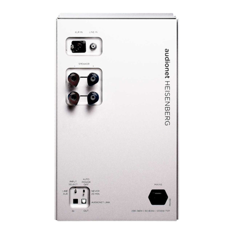
Audionet HEISENBERG user manual

Audionet

Audionet HEISENBERG user manual

Kustom Dual 30 RC owner's manual

Kustom

Kustom Dual 30 RC owner's manual

Harman JBL Club A754 owner's manual

Harman

Harman JBL Club A754 owner's manual

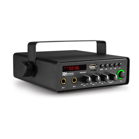
Power Dynamics 952.044 instruction manual

Power Dynamics

Power Dynamics 952.044 instruction manual

Pro-Ject Audio Systems Phono Box DS Instructions for use

Pro-Ject Audio Systems

Pro-Ject Audio Systems Phono Box DS Instructions for use

manuals.online logo
manuals.online logoBrands
  • About & Mission
  • Contact us
  • Privacy Policy
  • Terms and Conditions

Copyright 2025 Manuals.Online. All Rights Reserved.