Sonodyne BMS 205 User manual
multi-channel bass manager owners manual
BMS205&BMS205r
BMS 205 Page 1
Statutory Information
Thank you for selecting the Sonodyne BMS 205 multi-channel bass manager.
Please read through this owner’s manual carefully for details on product features and operation. Please
unpack with care and retain the packaging for future use.
This symbol warns there is uninsulated (dangerous) voltage in the cabinet of the unit.
This symbol indicates there are important instructions on operation and maintenance.
IMPORTANT SAFETY INSTRUCTIONS
1. The unit should be connected only to a wall outlet providing the correct mains voltage and frequency as
printedontheproduct.
2. Connecttheunittothemainsonlywiththemainscablesuppliedwiththeunit.
3. Ensure that the wall outlet is properly earthed, that is, the earth must be connected to a earth bus-bar which
connects to other audio equipments and is not shared by noisy equipments like computers, air-
conditioners, lighting appliances etc. The earth connection must be checked and certified by a qualified
electricalengineer.
4. Do not place the unit on an unstable surface that may topple and cause the unit to fall, thereby causing
injurytotheuserorotherpeople.
5. Do not place the unit outdoors where it may be exposed to strong sunlight, rain or moisture. Do not place it
nearawaterbodyorsprinkler.
6. Donotcovertheunitorblocktheventilationholesonthetopcoverwhichmaycauseittoheatup.
7. Donotplacetheunitnearheatradiatingitemslikestoves,radiatoretc.
8. Donotallowliquidoranychemicaltospillonorintotheproduct.
9. Do not allow the mains cord to be trodden or pinched particularly at the wall outlets or at the point of entry of
thecordintotheunit.
10. Do not open the unit or attempt to service it yourself. There is no user-serviceable part inside. Refer
servicingtoqualifiedservicepersonnelonly.
11. Replaceonlywiththesametypeandratingoffuseasprintedontheproduct.
12. Donotoverloadwalloutletsthatprovidepowertothisunit.

BMS 205
Introduction ∑Inside the box
Page 2
Congratulations on your purchase of the BMS 205, multichannel bass manager. This unique rack mount
device with its wired remote, the BMS 205r, is an excellent solution to monitor in dual or multichannel
modes, with or without a dedicated LFE unit (subwoofer).
Inside the box please find:
BMS 205:
∑1 x BMS 205 bass manager
1 x power cord
BMS 205r:
1 x BMS 205r wired remote control
1 x desktop pad
∑
∑
∑

BMS 205
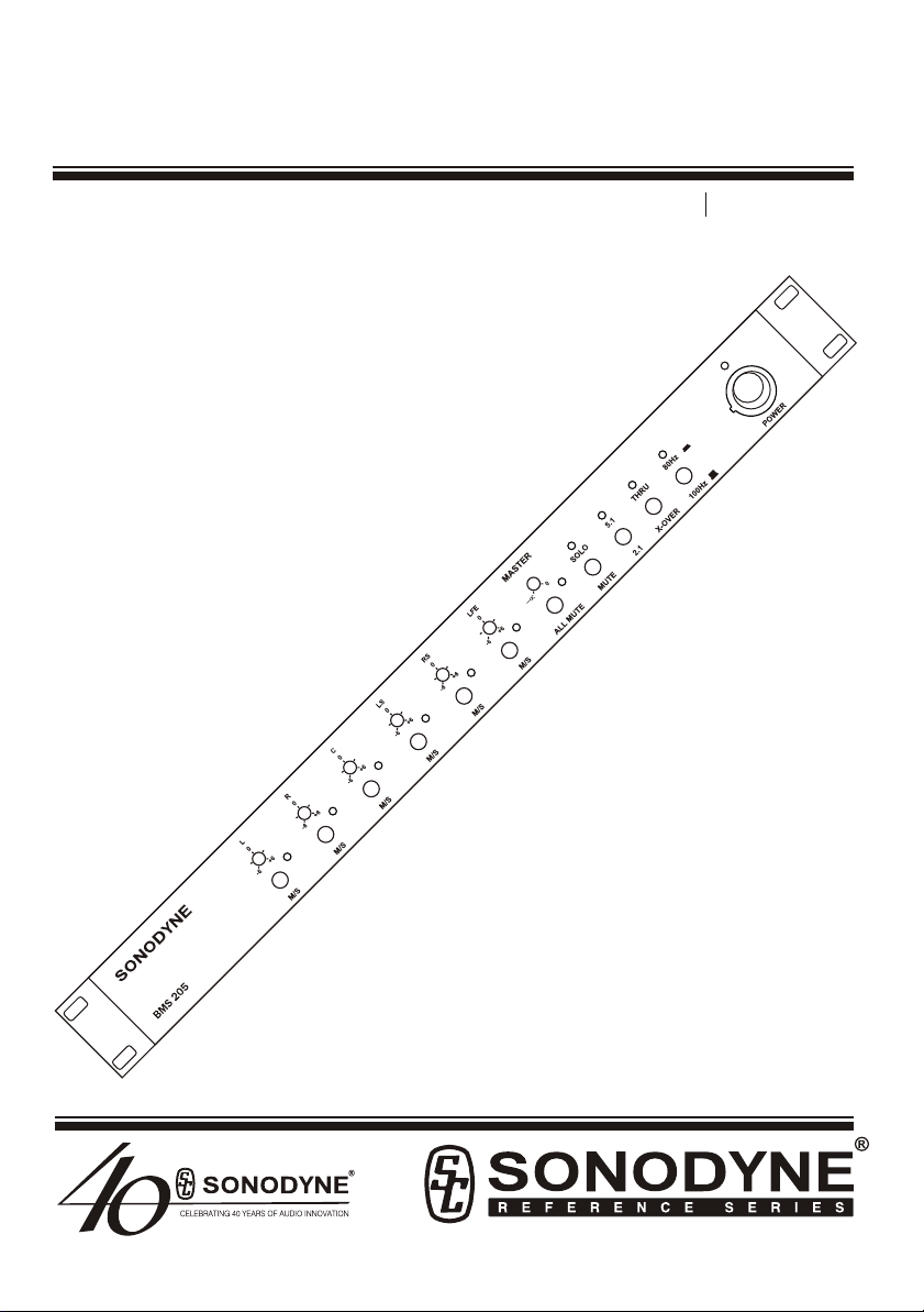
Fig 1: Front View
Page 3
1 2
3
4 5 8 10 12 14 16
6 7 9 11 13 15

Controls & Switches: Front Panel
Page 4
Please refer to Fig 1. (Page 3)
1) GAIN TRIM: This recessed control allows for each channel level (input) to be trimmed from -6 to +6
dB with centre position at 0 dB
2) MUTE/ SOLO LED: When this glows red, it is an indication that the Mute/Solo Option has been
selected for that channel; please see item 7 for more details.
3) MUTE/ SOLO SWITCH: This will Mute / Solo the specific channel depending on whether the Mute /
Solo mode has been selected; please see item 7 for more details
4) MASTER: This is a master level control for ALL channels; and varies from minimum to 0 dB.
5) ALL MUTE LED: This, when red, indicates that all channels have been muted
6) ALL MUTE SWITCH: Press this to MUTE all channels; Irrespective of the position of the MUTE/SOLO
switch ALL MUTE will mute all channels.
7) MUTE / SOLO global mode switch: The BMS 205 offers muting / soloing of each channel; Please
select the global mode that you desire and the independent channel M/S switch (item 3) shall
function accordingly.
8) SOLO LED: This, when red, indicates that the SOLO global mode has been selected
9) 2.1 / 5.1 MODE SWITCH: The BMS 205 outputs will derive and process the signal from its inputs in a
fashion as described in the table in Fig. 3 (page 7). This switch allows you to select the desired mode
of operation
10) 5.1 MODE LED: This, when red, indicates that the 5.1 operation mode has been selected
11) X-OVER/ THRU MODE SWITCH: The user can choose either BMS configuration using this switch.
Please refer to the Table in Figure 3 for the resulting effects of both modes, which will then allow you
to use this in conjunction with the the 2.1 / 5.1 mode switch
12) THRU MODE LED: This, when red, indicates that the THRU mode has been selected.
13) 100 Hz / 80 Hz mode switch: You may choose one of these two bass management frequencies that
will effect the LPF of the LFE channel and the HPF of the other channels. This will be effective if the
XOVER mode has been selected
14) 80 Hz LED: This indicates that the bass management frequency selected is 80 Hz
15) MAINS POWER ON SWITCH: Please switch on the BMS 205 first and then switch on the monitors,
and the reverse while switching off.
16) MAINS POWER ON INDICATOR LED
BMS 205
Page 5
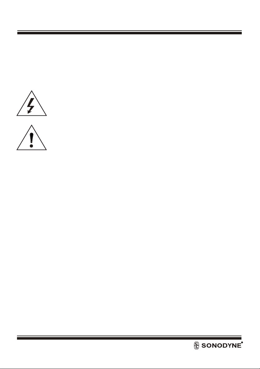
Fig. 2: Rear Panel
17 18 19 20 21 22
BMS 205

BMS 205 Page 6
Controls & Switches: Rear Panel
Please refer to Fig. 2 (Page 5)
17) MAINS POWER SOCKET: This is available in either 115 or 230 Volt, specific to markets
18) MAINS FUSE COMPARTMENT: rating is Schurter make 20mm, 0.125A, Slow blow ( 0034.3108)FST
type for 230V unit and Schurter make 20mm, 0.250A, Slow blow (0034.3111) FST. Please replace
with same type and value.
19) RJ45 SOCKET: This is to connect the BMS 205r to the BMS 205. Use RJ45 cable with “Straight
Through” configuration i.e. 1:1 connections on both ends.
20) OUTPUTS: Please connect, using balanced XLRs, the active speakers / power amps, to channels as
labeled. The XLR pin configuration should be: Pin 1 = GND, Pin 2 = Hot (+) , Pin 3 = Cold (-)
21) GND LIFT SWITCH: This can be a useful tool to get rid of unwanted buzz/ hum created due to
earthing / ground loop issues. Please experiment for best results
22) INPUTS: Please connect, using balanced XLRs, the 6 inputs from a decoder / mixer channels as
labeled. The XLR pin configuration should be: Pin 1 = GND, Pin 2 = Hot (+) , Pin 3 = Cold (-)

BMS 205 Page 7
Fig 3: Configurations
MODE BMS L OUT R OUT C OUT LS OUT RS OUT LFE OUT
SETTING
2.1 THRU L R - - - SUMMED
MONO
L+R
2.1 X-OVER L WITH R WITH - - - SUMMED
HPF HPF MONO
WITH LPF
5.1 THRU L R C LS RS LFE
5.1 X-OVER L WITH R WITH C WITH LS WITH RS WITH LFE +
HPF HPF HPF HPF HPF SUMMED
MONO
{L+R+LS+
RS+C}
WITH LPF)

BMS 205 Page 8
FIG. 4: BMS 205r ∑Features
1) MUTE LED: this will glow when the master mute has been selected either from the main console or
from the MUTE switch on the remote (please see item 4)
2) MASTER:ThisisamasterlevelcontrolforALLchannelsandvariesfrommuteto0dB.
3) POWER on LED: With the connection established to the BMS 205, this glows green when the BMS 205 is
ON
4) MUTEswitch:PresstoMUTE
5) RJ45 socket for connection to main unit. Use RJ45 cable with “ Straight Through “ configuration i.e. 1:1
connectionsonboththeends.
MUTE POWER
µ0 dB
REMOTE
MUTE
BMS 205R
1
2
3
4
5

Specifications: BMS 205
Page 9
BMS 205
INPUT CONNECTIONS 6 x XLR F (lockable)
OUTPUT CONNECTIONS 6 x XLR M
INPUT SIGNAL-SENSITIVITY 5.1 mode - (0 dBu) rated
2.1 mode - (0 dBu) rated
OUTPUT SIGNAL LEVEL 5.1 mode - (0 dBu) rated
2.1 mode - (0 dBu) rated
FREQUENCY RESPONSE Thru mode - 20 Hz ~ 20 kHz (-3 dB)
X-over mode - 80 and100 Hz (LPF & HPF)
THD < 0.08%
S/N RATIO > 70 dB
CROSSTALK > 70 dB
DIM. (H x W x D) 44 x 482 x 165 mm
NET WEIGHT 2.75 Kg
POWER SOURCE 230V AC, 50Hz or
(115V AC,60Hz optional – Factory fitted)

BMS 205
POWER INPUT Via CAT5 cable from BMS 205
INPUT CONNECTIONS CAT 5 (Straight Thru) cable between
BMS 205 and BMS 205r
FEATURES a) Master volume control
b) Power ON LED indication
c) Master Mute - ON LED indication
d) Desk top cushion pad provided
MECHANICAL CONSTRUCTION Table top aluminum housing with a
desk top cushion pad
DIMENSIONS (H x W x D) 42 x 140 x 88 mm
NET WEIGHT 0.375 Kg
Specifications: BMS 205r
Page 10

This manual suits for next models
1
Table of contents


