manuals.online logo
Brands
  1. Home
  2. •
  3. Brands
  4. •
  5. Sony
  6. •
  7. Camcorder
  8. •
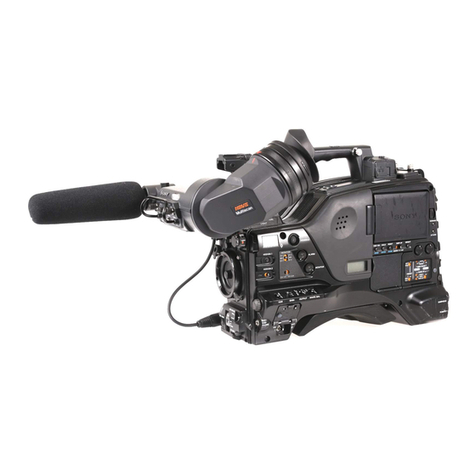
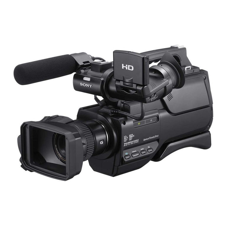
  9. Sony Handycam NEX-VG900 User manual

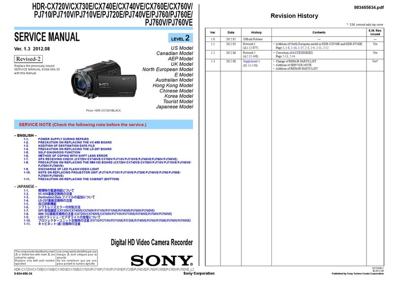
Sony Handycam NEX-VG900 User manual

NEX-VG900/VG900E_L2 Sony Corporation
SERVICE MANUAL
Revision History
LEVEL 2Ver. Date History Contents S.M. Rev.
issued
1.0 2012.10 Official Release — —
SERVICE NOTE (Check the following note before the service.)
983469531.pdf
2012J08-1
© 2012.10
Published by Sony Techno Create Corporation
Ver. 1.0 2012.10
INTERCHANGEABLE LENS DIGITAL HD VIDEO CAMERA RECORDER
The components identified
by mark 0or dotted line with
mark 0are critical for safety.
Replace only with part number
specified.
Les composants identifiés par
une marque 0sont critiques
pour la sécurité.
Ne les remplacer que par une
pièce portant le numéro spécifié.
US Model
Canadian Model
AEP Model
E Model
Chinese Model
Japanese Model
Tourist Model
1-1. POWER SUPPLY DURING REPAIRS
1-2. PRECAUTION ON REPLACING THE VC-1006 BOARD
1-3. PRECAUTION FOR REPLACEMENT OF IMAGER UNIT
1-4. NOTES FOR REPLACING THE EVF DISPLAY DEVICE (LCD902) OR THE VC-1006
BOARD
1-5. ADDITION OF DESTINATION DATA FILE
1-6. PRECAUTION ON REPLACING THE MB N PLATE AND NDF UNIT
1-7. SELF-DIAGNOSIS FUNCTION
1-8. METHOD OF COPING WITH LENS ERROR
1-9. NOTE ON REPLACEMENT OF MOUNT ADAPTOR (LA-EA3) (SERVICE)
9-834-695-31
– ENGLISH –
– JAPANESE –
1-1. 修理時の電源供給について
1-2. VC-1006基板交換時の注意
1-3. イメージャーユニット交換時の注意
1-4. EVF表示素子(LCD902)またはVC-1006基板交換時の注意
1-5. DestinationDataファイルの追加について
1-6. MBNプレートとNDFユニット交換時の注意
1-7. 自己診断機能
1-8. レンズエラーの対処方法
1-9. マウントアダプター(LA-EA3)(サービス)交換時の注意
NEX-VG900/VG900E
Photo: NEX-VG900Photo: LA-EA3
NEX-VG900/VG900E_L2
– 2 –
SPECIFICATIONS
System
Signal format:
NEX-VG900:
NTSC color, EIA standards
HDTV 1080/60i, 1080/60p specification
NEX-VG900E:
PAL color, CCIR standards
HDTV 1080/50i, 1080/50p specification
NTSC color, EIA standards HDTV 1080/60i
specification (24p recording mode only)
Movie recording format:
HD: MPEG-4 AVC/H.264 AVCHD format
Ver.2.0 compatible
STD: MPEG2-PS
Audio recording system:
Dolby Digital 2ch/5.1ch
Dolby Digital 5.1 Creator
Photo file format
DCF Ver.2.0 Compatible
Exif Ver.2.3 Compatible
MPF Baseline Compatible
Recording media (Movie/Photo)
“Memory Stick PRO Duo” media
SD card (Class 4 or faster)
Viewfinder:
Electronic viewfinder: Color
Screen size: 1.3 cm (0.5 type)
Effective pixel number: 2 359 296 dots
(3 072 × 768)
Image device: 36.1 mm × 24.3 mm (35 mm full
size) CMOS sensor
Recording pixels (still 3:2 JPEG):
Max. 24.0 mega (6 000 × 4 000) pixels
Gross: Approx. 24 660 000 pixels
Effective (movie, 16:9):
Approx. 20 300 000 pixels
Effective (photo, 16:9):
Approx. 20 300 000 pixels
Effective (photo, 3:2):
Approx. 24 300 000 pixels
Color temperature: [Auto], [One Push], [Indoor]
(3 200 K), [Outdoor] (5 600 K), manual
(2 500 K - 9 900 K)
Minimum illumination
8 lx (lux) (in default setting, shutter speed
1/60 second (NEX-VG900) / 1/50 second
(NEX-VG900E), gain: 30 dB, aperture F3.5)
Input/Output connectors
A/V Remote Connector: Component/video and
audio output jack
HDMI OUT jack: HDMI mini connector
USB jack: mini-AB
NEX-VG900E: output only
Headphone jack: Stereo minijack (ø 3.5 mm)
MIC input jack: Stereo minijack (ø 3.5 mm)
LCD screen
Picture: 7.5 cm (3.0 type, aspect ratio 16:9)
Total number of pixels: 921 600 (1 920 × 480)
General
Power requirements: DC 6.8 V/7.2 V (battery
pack) DC 8.4 V (AC Adaptor)
Average power consumption:
During camera recording using viewfinder at
normal brightness:
HD: 5.2 W STD: 5.0 W
During camera recording using LCD screen
at normal brightness:
HD: 4.7 W STD: 4.5 W
Operating temperature: 0 °C to 40 °C (32 °F to
104 °F)
Storage temperature: –20 °C to + 60 °C (–4 °F to
+140 °F)
Dimensions (approx.):
105 mm × 130 mm × 223 mm (4 1/4 in. ×
5 1/8 in. × 8 7/8 in.) (w/h/d) including the
projecting parts
105 mm × 130 mm × 227 mm (4 1/4 in. ×
5 1/8 in. × 9 in.) (w/h/d) including the
projecting parts, supplied battery pack
(NP-FV70) and mount adaptor (LA-EA3)
Mass (approx.)
Camcorder body only:
Approx. 825 g (1 lb 13 oz)
When recording:
Approx. 1 030 g (2 lb 4 oz)
(With supplied battery pack (NP-FV70) and
mount adaptor LA-EA3)
AC Adaptor AC-L200D
Power requirements: AC 100 V - 240 V,
50 Hz/60 Hz
Current consumption: 0.35 A - 0.18 A
Power consumption: 18 W
Output voltage: DC 8.4 V
Output current: 1.7 A
Operating temperature: 0 °C to 40 °C (32 °F to
104 °F)
Storage temperature: –20 °C to + 60 °C (–4 °F to
+140 °F)
Dimensions (approx.): 48 mm × 29 mm × 81 mm
(1 15/16 in. × 1 3/16 in. × 3 1/4 in.) (w/h/d)
excluding the projecting parts
Mass (approx.): 150 g (5.0 oz) excluding the
power cord (mains lead)
Rechargeable battery pack NP-FV70
Maximum output voltage: DC 8.4 V
Output voltage: DC 6.8 V
Maximum charge voltage: DC 8.4 V
Maximum charge current: 3.0 A
Capacity
Typical: 14.0 Wh (2 060 mAh)
Minimum: 13.0 Wh (1 960 mAh)
Type: Li-ion
Mount adaptor (LA-EA3)
Dimensions (approx.):
76 mm × 69 mm × 35 mm (3 in. × 2 3/4 in. ×
1 7/16 in.) (w/h/d)
Mass (approx.)
105 g (3.7 oz)
Design and specifications of your camcorder and
accessories are subject to change without notice.
●Manufactured under license from Dolby
Laboratories.
– ENGLISH – – JAPANESE –
概略仕様
システム
信号方式
NTSCカラー、EIA標準方式
HDTV 1080/60i方式、1080/60p方式
ビデオ記録方式
HD画質:MPEG-4 AVC/H.264 AVCHD規格
Ver.2.0準拠
STD画質:MPEG-2 PS
音声記録方式
Dolby Digital 2ch/5.1ch
ドルビーデジタル5.1クリエーター搭載
静止画ファイルフォーマット
:DCF Ver2.0準拠
:Exif Ver2.3準拠
:MPF Baseline準拠
記録メディア(動画・静止画)
メモリースティック PRO デュオ
SDカード(Class4以上)
ファインダー
電子ファインダー
画面サイズ:1.3cm(0.5型)
有効画素数:2 359 296ドット
(3 072 ×768相当)
撮像素子:36.1 mm ×24.3 mm(35mmフルサイズ)
CMOSセンサー
記録画素数:静止画時 最大2 400万画素(6 000
×4 000)(3:2)(JPEG)
総画素数:約2 466万画素
動画時有効画素数(16:9):約2 030万画素
静止画時有効画素数(16:9):約2 030万画素
静止画時有効画素数(3:2):約2 430万画素
色温度切り換え:[オート]、[ワンプッシュ]、[屋内]
(3 200 K)、[屋外](5 600 K)、マニュアル
(2 500 K - 9 900 K)
最低被写体照度:8 lx(lux)お買い上げ時 シャッター
スピード:1/60、ゲイン:30dB、絞り:F3.5
入/出力端子
A/Vリモート端子:コンポーネント、映像音声出力兼
用端子
HDMI OUT端子:HDMIミニコネクタ
USB端子:mini-AB
ヘッドホン端子:ステレオミニジャック(ø3.5 mm)
MIC入力端子:ステレオミニジャック(ø3.5 mm)
液晶モニター
画面サイズ:7.5 cm(3.0型、アスペクト比16:9)
総ドット数:921 600ドット
横1 920×縦480
電源部、その他
電源電圧:バッテリー端子入力 6.8 V/7.2 V
DC端子入力 8.4 V
消費電力:
ファインダー使用時、明るさ標準:
HD:5.2 W STD:5.0 W
液晶モニター使用時、明るさ標準
HD:4.7 W STD:4.5 W
動作温度:0 ℃〜 40 ℃
保存温度:−20 ℃〜 +60 ℃
外形寸法:
105 mm ×130 mm ×223 mm
(突起部を含む)(幅×高さ×奥行き)
105 ×130 ×227 mm
(突起部、付属バッテリー (NP-FV70)、マウント
アダプター(LA-EA3)を含む)
(幅×高さ×奥行き)
本体質量:
本体質量 約825g
撮影時総質量 約1 030g
(付属バッテリー (NP-FV70)、マウントアダプター
(LA-EA3)含む)
ACアダプター AC-L200D
電源:AC 100 V - 240 V、50 Hz/60 Hz
消費電流:0.35 A - 0.18 A
消費電力:18 W
定格出力:DC 8.4 V*
動作温度:0 ℃〜 40 ℃
保存温度:−20 ℃〜 +60 ℃
外形寸法:約 48×29×81 mm(最大突起部を除く)
(幅×高さ×奥行き)
質量:約150 g(本体のみ)
*その他の仕様についてはACアダプターのラベルを
ご覧ください。
リチャージャブルバッテリーパック
NP-FV70
最大電圧:DC 8.4 V
公称電圧:DC 6.8 V
容量:
公称容量:14.0 Wh(2 060 mAh)
定格(最小)容量:13 Wh(1 960 mAh)
使用電池:Li-ion
マウントアダプター(LA-EA3)
外形寸法:
約76 ×69 ×35 mm(幅×高さ×奥行き)
質量:約105g
本機やアクセサリーの仕様および外観は、改良のた
め予告なく変更することがありますが、ご了承くだ
さい。
•ドルビーラボラトリーズからの実施権に基づき製
造されています。
Model information table
Model NEX-VG900 NEX-VG900E
Destination US, CND, E, J AEP, E, CH, JE
COLOR system NTSC PAL
Internal Recording media - -
Lens - -
Projector - -
GPS - -
Hot shoe - -
Charging capacitor (for flash) - -
• Abbreviation
CH : Chinese model
CND : Canadian model
J : Japanese model
JE : Tourist model
NEX-VG900/VG900E_L2
– 3 –
SAFETY-RELATED COMPONENT WARNING!!
COMPONENTS IDENTIFIED BY MARK 0OR DOTTED LINE WITH
MARK 0ON THE SCHEMATIC DIAGRAMS AND IN THE PARTS LIST
ARE CRITICAL TO SAFE OPERATION. REPLACE THESE COMPO-
NENTS WITH SONY PARTS WHOSE PART NUMBERS APPEAR AS
SHOWN IN THIS MANUAL OR IN SUPPLEMENTS PUBLISHED BY
SONY.
ATTENTION AU COMPOSANT AYANT RAPPORT
À LA SÉCURITÉ!
LES COMPOSANTS IDENTIFIÉS PAR UNE MARQUE 0SUR LES
DIAGRAMMES SCHÉMATIQUES ET LA LISTE DES PIÈCES SONT
CRITIQUES POUR LA SÉCURITÉ DE FONCTIONNEMENT. NE REM-
PLACER CES COMPOSANTS QUE PAR DES PIÈCES SONY DONT
LES NUMÉROS SONT DONNÉS DANS CE MANUEL OU DANS LES
SUPPLÉMENTS PUBLIÉS PAR SONY.
Caution
Danger of explosion if battery is incorrectly replaced.
Replace only with the same or equivalent type.
Dispose of used batteries according to the instructions.
Caution
電池の交換は,正しく行わないと破裂する恐れがあります。
電池を交換する場合には必ず同じ型名の電池又は同等品と
交換してください。
使用済み電池は,取扱指示に従って処分してください。
CHEMICALS
Some chemicals used for servicing are highly volatile.
Their evaporation caused by improper management affects your health
and environment, and wastes resources.
Manage the chemicals carefully as follows.
• Store chemicals sealed in a specific place to prevent from exposure
to high temperature or direct sunlight.
• Avoid dividing chemicals into excessive numbers of small containers
to reduce natural evaporation.
• Keep containers sealed to avoid natural evaporation when chemicals
are not in use.
• Avoid using chemicals as much as possible. When using chemicals,
divide only required amount to a small plate from the container and
use up it.
PLASTIC PARTS
Be careful to the following points for plastic parts used in this unit.
• Use a piece of cleaning paper or cleaning cloth for cleaning plastic
parts. Avoid using chemicals.
Even if you have to use chemicals to clean heavy dirt, don’t use paint
thinner, ketone, nor alcohol.
• Insert the specific screws vertically to the part when installing a
plastic part.
Be careful not to tighten screws too much.
UNLEADED SOLDER
This unit uses unleaded solder.
Boards requiring use of unleaded solder are printed with the lead free
mark (LF) indicating the solder contains no lead.
(Caution: Some printed circuit boards may not come printed with the
lead free mark due to their particular size.)
: LEAD FREE MARK
Be careful to the following points to solder or unsolder.
• Set the soldering iron tip temperature to 350 °C approximately.
If cannot control temperature, solder/unsolder at high temperature
for a short time.
Caution: The printed pattern (copper foil) may peel away if the
heated tip is applied for too long, so be careful!
Unleaded solder is more viscous (sticky, less prone to
flow) than ordinary solder so use caution not to let solder
bridges occur such as on IC pins, etc.
• Be sure to control soldering iron tips used for unleaded solder and
those for leaded solder so they are managed separately. Mixing un-
leaded solder and leaded solder will cause detachment phenomenon.
SAFETY CHECK-OUT
After correcting the original service problem, perform the following
safety checks before releasing the set to the customer.
1. Check the area of your repair for unsoldered or poorly-soldered
connections. Check the entire board surface for solder splashes and
bridges.
2. Check the interboard wiring to ensure that no wires are “pinched”
or contact high-wattage resistors.
3. Look for unauthorized replacement parts, particularly transistors,
that were installed during a previous repair. Point them out to the
customer and recommend their replacement.
4. Look for parts which, through functioning, show obvious signs of
deterioration. Point them out to the customer and recommend their
replacement.
5. Check the B+ voltage to see it is at the values specified.
6. Flexible Circuit Board Repairing
• Keep the temperature of the soldering iron around 350 °C during
repairing.
• Do not touch the soldering iron on the same conductor of the circuit
board (within 3 times).
• Be careful not to apply force on the conductor when soldering or
unsoldering.
各種薬品の取り扱いについて
現在使用されている薬品の中には揮発性の高い薬品もありま
す。
それらを不用意に取り扱い蒸発させてしまうと,環境や健康へ
影響を与えたり,資源の無駄使いになります。
各種薬品は,下記の点に注意して取り扱ってください。
・ 保管場所を定め,高温になったり直射日光の当たらない場
所に密閉して保管してください。
・ 小分け(ハンドラップ等)する数は必要最小限に留め,容器
による自然蒸発を防いでください。
・ 作業に使用しない時は,必ずキャップ等をして自然蒸発を
防いでください。
・ 薬品を使用する回数を極力少なくし,使用する場合は使用
する量だけ容器より出して受け皿に残さないようにしてく
ださい。
樹脂系部品の取り扱いについて
本機に使用されている樹脂系の部品は,下記の点に注意して取
り扱ってください。
・ 清掃には薬品を使用せず,清掃紙や清掃布を使用してくだ
さい。
 やむを得ず汚れがひどくて薬品を使用する場合は,シン
ナー,ケトン,エーテルは使用しないでください。
・ 各部品の取り付けには指定されたねじを使用し,部品に対
して垂直に取り付けてください。
 また,ねじを締め付ける時は,無理な力を加えないでくだ
さい。
1. 注意事項をお守りください。
 サービスのとき特に注意を要する個所については,キャビ
ネット,シャーシ,部品などにラベルや捺印で注意事項を
表示しています。これらの注意書きおよび取扱説明書等の
注意事項を必ずお守りください。
2. 指定部品のご使用を
 セットの部品は難燃性や耐電圧など安全上の特性を持った
ものとなっています。従って交換部品は,使用されていた
ものと同じ特性の部品を使用してください。特に回路図,
部品表に0印で指定されている安全上重要な部品は必ず指
定のものをご使用ください。
3. 部品の取付けや配線の引きまわしはもとどおりに
 安全上,チューブやテープなどの絶縁材料を使用したり,
プリント基板から浮かして取付けた部品があります。
 また内部配線は引きまわしやクランパによって発熱部品や
高圧部品に接近しないよう配慮されていますので,これら
は必ずもとどおりにしてください。
4. サービス後は安全点検を
 サービスのために取外したネジ,部品,配線がもとどおり
になっているか,またサービスした個所の周辺を劣化させ
てしまったところがないかなどを点検し,安全性が確保さ
れていることを確認してください。
5. チップ部品交換時の注意
 ・ 取り外した部品は再使用しないでください。
 ・ タンタルコンデンサのマイナス側は熱に弱いため交換時
は注意してください。
6. フレキシブルプリント基板の取扱いについて
 ・ こて先温度を350℃に設定して行ってください。
 ・ 同一パターンに何度もこて先を当てないでください。
  (3回以内)
 ・ パターンに力が加わらないよう注意してください。
サービス,点検時には次のことにご注意ください。
無鉛半田について
本機には無鉛半田が使用されています。
無鉛半田を使用している基板には,無鉛(LeadFree)を意味する
レッドフリーマークがプリントされています。
(注意:基板サイズによっては,無鉛半田を使用していてもレッ
ドフリーマークがプリントされていないものがありま
す)
:レッドフリーマーク
無鉛半田は,下記の点に注意して使用してください。
・ 半田こてのこて先温度は約350℃に設定してください。
 温度調節が無理な場合は,高温短時間で作業を行ってくだ
さい。
 注意:半田こてを長く当てすぎると,基板のパターン(銅
箔)がはがれてしまうことがありますので,注意して
ください。また,従来の半田よりも粘性が強いため,
IC端子などが半田ブリッジしないように注意してく
ださい。
・ 半田こてのこて先は,必ず無鉛半田用と有鉛半田用に分け
て管理してください。
 無鉛半田と有鉛半田が混在すると剥離現象が発生してしま
います。
– ENGLISH – – JAPANESE –
1-1
NEX-VG900/VG900E_L2
1. SERVICE NOTE
1-1. POWER SUPPLY DURING REPAIRS
In this unit, about 10 seconds after power is supplied to the battery terminal using the regulated power supply (8.4 Vdc), the power is shut off
so that the unit cannot operate.
These following method is available to prevent this.
Method:
Use the AC power adaptor.
1-2. PRECAUTION ON REPLACING THE VC-1006 BOARD
Note the following when replacing the board.
Destination Data
When you replace to the repairing board, the written destination data of repairing board also might be changed to original setting.
Start the Adjust Manual in the Adjust Station and execute the “DESTINATION DATA WRITE”.
USB Serial No.
The set is shipped with a unique ID (USB Serial No.) written in it.
This ID has not been written in a new board for service, and therefore it must be entered after the board replacement.
Start the Adjust Manual in the Adjust Station and execute the “USB SERIAL No. INPUT”.
Imager DRA Data
Extract the imager data from the set before the VC board replacement using “Imager DRA Data Reference” in the DATA tab of the Adjust manual.
After the VC board has been replaced, write the data extracted from the set before the VC board replacement in the set using “Imager DRA Data Input”
in the ADJUST tab of the Adjust manual.
EVF WB Adjustment data value
WB adjustment values of each EVF display device (LCD902) are stored on the VC board.
Therefore, when the LCD902 or the VC board has been replaced, write WB adjustment values.
Product ID
The unit is shipped after an ID (PRODUCT ID) unique to each model has been written.
This ID is not written to a new replacement board. Enter a unique ID after the board has been replaced.
Start the Adjust Manual in the Adjust Station and execute the “PRODUCT ID & USB SERIAL No. INPUT”.
Setting PRODUCT ID
No PRODUCT ID is set for a new replacement board.
Therefore, if the board is replaced with a new replacement board, a discrepancy with the user-registered PRODUCT ID provided by the customer
may be generated.
After the board has been replaced with a new replacement board, start Adjust Manual from Adjust Station and execute “PRODUCT ID & USB
SERIAL No. INPUT”.
1-3. PRECAUTION FOR REPLACEMENT OF IMAGER UNIT
In this model, the following procedure is required when the imager unit is replaced.
• In the case that the imager data can be extracted from the set before the replacement, refer to “Imager DRA Data” in “1-2. PRECAUTION ON
REPLACING THE VC-1006 BOARD”.
• In the case that the imager data cannot be extracted from the set before the replacement, replace both VC board and imager unit.
Capture the data to PC from CD-ROM supplied with the imager unit when it is ordered.
Write the captured data in the set using “Imager DRA Data Input” in the ADJUST tab of the Adjust manual.
After all adjustment items have been completed, execute “Phase Detection AF Check” on the SERVICE tab of the Adjust manual.
– ENGLISH –
1-4. NOTES FOR REPLACING THE EVF DISPLAY DEVICE (LCD902) OR THE VC-1006 BOARD
WB adjustment values of each EVF display device (LCD902) are stored on the VC board.
Therefore, when the LCD902 or the VC board has been replaced, write WB adjustment values.
Adjustment
value
1-A
1-A
When LCD902 is replaced:
1. Check and write down the adjustment values printed on the LCD902 label.
2. After the LCD902 has been replaced, execute “EVF WB Adj” on the ADJUST tab by using the Adjust manual to write the adjustment values.
When replacing VC board (in case adjustment values can be read):
1. In case the unrepaired unit starts and adjustment values can be read by using the Adjust manual, execute “ADJUSTMENT DATA BACKUP” on
the DATA tab.
2. After the VC board has been replaced with a VC board for repair, execute “ADJUSTMENT DATA BACKUP” on the DATA tab of the Adjust
manual to write the extracted data to the unit.
When replacing VC board (in case adjustment values cannot be read):
1. When adjustment values cannot be read from the unrepaired unit, disassemble the unit and write down the adjustment values printed on the LCD902
label.
2. After the VC board has been replaced with a VC board for repair, execute “EVF WB Adj.” on the ADJUST tab by using the Adjust manual to write
adjustment values to the unit.
1-5. ADDITION OF DESTINATION DATA FILE
If the Destination Data file included in the Adjust manual is old, “DESTINATION DATA WRITE” cannot be executed in some cases.
In that case, download a new Destination Data file from the TISS homepage according to the following procedure.
Note 1: To perform Destination Data Write for this model, the Adjust manual of the DSC-WX50 series must have been installed.
Install the Adjust manual of the DSC-WX50 series in advance.
Note 2: The actual image may differ from the image shown above.
1) If the Destination Data file in the Adjust manual in use is old, the window shown in Fig. 1 is displayed.
Click the [OK] button.
Fig. 1
2) The Destination Data Write window opens.
Check the version of the Destination Data file retained in the Adjust manual.
Destination Ver. window
1-2
NEX-VG900/VG900E_L2
– ENGLISH –
3) Search the model whose new Destination Data file you want to get on the TISS homepage.
When the Destination Data file has been updated, a file with a name “Destination File For ‘model name’.zip” is registered.
(Example) Destination File For DSC-WX50.zip
Furthermore, the version supported by the Destination Data file is shown in the Remarks column.
Note : If the Destination Data file has not been updated, contact the Service Headquarters.
4) Download the Destination Data file of the relevant model and unzip the file.
5) Execute “DESTINATION DATA WRITE” in the Adjust tab of the Adjust manual.
Click the [START] button.
6) Click the [File Update] button in the window.
7) A file selection screen opens. Select the Destination Data file to be added and click the [Open] button.
8) When the file has been successfully added, the following window opens.
9) Check the Destination Ver. window and confirm that the version has been updated.
Destination Ver. window

Other manuals for Handycam NEX-VG900

5

This manual suits for next models

1

Other Sony Camcorder manuals

Sony Handycam HDR-CX240 Reference guide

Sony

Sony Handycam HDR-CX240 Reference guide

Sony HDR SR5 - AVCHD 4MP 40GB High Definition Hard Disk Drive... User manual

Sony

Sony HDR SR5 - AVCHD 4MP 40GB High Definition Hard Disk Drive... User manual

Sony Handycam 4-170-893-12(1) User manual

Sony

Sony Handycam 4-170-893-12(1) User manual

Sony HDR-TD30V User manual

Sony

Sony HDR-TD30V User manual

Sony Handycam DCR-PC103E User manual

Sony

Sony Handycam DCR-PC103E User manual

Sony HDR-AS50R Instruction sheet

Sony

Sony HDR-AS50R Instruction sheet

Sony DSR PD170 - Camcorder - 380 KP User manual

Sony

Sony DSR PD170 - Camcorder - 380 KP User manual

Sony EVI HD7V User manual

Sony

Sony EVI HD7V User manual

Sony Handycam DCR-SR50E User manual

Sony

Sony Handycam DCR-SR50E User manual

Sony F35 Cinealta User manual

Sony

Sony F35 Cinealta User manual

Sony HDR-CX530E Reference guide

Sony

Sony HDR-CX530E Reference guide

Sony CCD-TRV15 User manual

Sony

Sony CCD-TRV15 User manual

Sony DCR-TRV50 - Digital Handycam Camcorder User manual

Sony

Sony DCR-TRV50 - Digital Handycam Camcorder User manual

Sony DVCAM DSR-PD100 User manual

Sony

Sony DVCAM DSR-PD100 User manual

Sony PXW-FS7K User manual

Sony

Sony PXW-FS7K User manual

Sony Handycam CCD-TR40 User manual

Sony

Sony Handycam CCD-TR40 User manual

Sony PXW-X180 User manual

Sony

Sony PXW-X180 User manual

Sony 4-191-794-11(1) User manual

Sony

Sony 4-191-794-11(1) User manual

Sony Handycam HDR-CX300 User manual

Sony

Sony Handycam HDR-CX300 User manual

Sony HDR-PJ800 User manual

Sony

Sony HDR-PJ800 User manual

Sony Hyper HAD SPT-M124 User manual

Sony

Sony Hyper HAD SPT-M124 User manual

Sony PMW-100 User manual

Sony

Sony PMW-100 User manual

Sony FCBEH3150 User manual

Sony

Sony FCBEH3150 User manual

Sony Handycam FDR-AX1 User manual

Sony

Sony Handycam FDR-AX1 User manual

Popular Camcorder manuals by other brands

Vivitar DVR 830XHD owner's manual

Vivitar

Vivitar DVR 830XHD owner's manual

Panasonic HX-WA20PP Service manual

Panasonic

Panasonic HX-WA20PP Service manual

Canon FS1 instruction manual

Canon

Canon FS1 instruction manual

Sharp VL-H400S Operation manual

Sharp

Sharp VL-H400S Operation manual

Panasonic AJ-D900WAP operating instructions

Panasonic

Panasonic AJ-D900WAP operating instructions

Samsung VP-D6550 Owner's instruction book

Samsung

Samsung VP-D6550 Owner's instruction book

Naxa NDC-402 instruction manual

Naxa

Naxa NDC-402 instruction manual

LG L320-BN owner's manual

LG

LG L320-BN owner's manual

Vivitar DVR 865HD user manual

Vivitar

Vivitar DVR 865HD user manual

Toshiba CAMILEO Z100 user guide

Toshiba

Toshiba CAMILEO Z100 user guide

Panasonic NV-VS40B operating instructions

Panasonic

Panasonic NV-VS40B operating instructions

Canon RC 260 instructions

Canon

Canon RC 260 instructions

Brinno TimeLapse TLC200 user manual

Brinno

Brinno TimeLapse TLC200 user manual

JVC GR-SXM68AC Schematic diagram

JVC

JVC GR-SXM68AC Schematic diagram

MYDLINK DCS-6100LH Quick installation guide

MYDLINK

MYDLINK DCS-6100LH Quick installation guide

SECURECOM V-5014B installation guide

SECURECOM

SECURECOM V-5014B installation guide

JVC AA-V15EG instruction manual

JVC

JVC AA-V15EG instruction manual

Canon LEGRIA HV40 instruction manual

Canon

Canon LEGRIA HV40 instruction manual

manuals.online logo
manuals.online logoBrands
  • About & Mission
  • Contact us
  • Privacy Policy
  • Terms and Conditions

Copyright 2025 Manuals.Online. All Rights Reserved.