manuals.online logo
Brands
  1. Home
  2. •
  3. Brands
  4. •
  5. Sony
  6. •
  7. CD Player
  8. •
  9. Sony CDP-C301M User manual

Sony CDP-C301M User manual

This manual suits for next models

1

Other Sony CD Player manuals

Sony WALKMAN D-CJ01 User manual

Sony

Sony WALKMAN D-CJ01 User manual

Sony Discman D-25 User manual

Sony

Sony Discman D-25 User manual

Sony CDP-M400CS - 400 Disc Megastorage® Cd... User guide

Sony

Sony CDP-M400CS - 400 Disc Megastorage® Cd... User guide

Sony CD Walkman D-NE509 User manual

Sony

Sony CD Walkman D-NE509 User manual

Sony CD Walkman D-E551 User manual

Sony

Sony CD Walkman D-E551 User manual

Sony G750PC Instruction Manual

Sony

Sony G750PC Instruction Manual

Sony CFDG700CP - Xplod Boombox User manual

Sony

Sony CFDG700CP - Xplod Boombox User manual

Sony MZ-N707 OpenMG Jukebox NOTES on installing &... User manual

Sony

Sony MZ-N707 OpenMG Jukebox NOTES on installing &... User manual

Sony Walkman D-NE730 User manual

Sony

Sony Walkman D-NE730 User manual

Sony CFD-ZW705 - Cd Radio Cassette-corder User manual

Sony

Sony CFD-ZW705 - Cd Radio Cassette-corder User manual

Sony CFD-E75 Marketing User manual

Sony

Sony CFD-E75 Marketing User manual

Sony CFD-Z500 - Cd Radio Cassette-corder User manual

Sony

Sony CFD-Z500 - Cd Radio Cassette-corder User manual

Sony DVX-100 - 10 Disc Dvd Changer User manual

Sony

Sony DVX-100 - 10 Disc Dvd Changer User manual

Sony MXD-D4 User manual

Sony

Sony MXD-D4 User manual

Sony CDX-GT320MP User manual

Sony

Sony CDX-GT320MP User manual

Sony CDP-C345 User manual

Sony

Sony CDP-C345 User manual

Sony CFD-758 User manual

Sony

Sony CFD-758 User manual

Sony CDX-CA850 User manual

Sony

Sony CDX-CA850 User manual

Sony CFD-E95L User manual

Sony

Sony CFD-E95L User manual

Sony CDP-CX255 User manual

Sony

Sony CDP-CX255 User manual

Sony D-NE715 - Portable Cd Player User manual

Sony

Sony D-NE715 - Portable Cd Player User manual
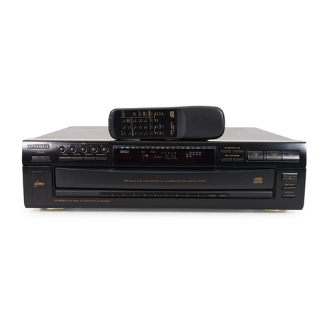
Sony D-E705 - Compact Disc Player User manual

Sony

Sony D-E705 - Compact Disc Player User manual

Sony ICF-CD73V User manual

Sony

Sony ICF-CD73V User manual

Sony CDP-970 User manual

Sony

Sony CDP-970 User manual

Popular CD Player manuals by other brands

Arcam CD23 Handbook

Arcam

Arcam CD23 Handbook

Sanyo MCD-Z1F Service manual

Sanyo

Sanyo MCD-Z1F Service manual

JVC RC-ST3SL instructions

JVC

JVC RC-ST3SL instructions

Technics SL-P9066 operating instructions

Technics

Technics SL-P9066 operating instructions

Marantz HD-CD1 quick start guide

Marantz

Marantz HD-CD1 quick start guide

Philips AZ1140 Instrukcja obs?ugi

Philips

Philips AZ1140 Instrukcja obs?ugi

Alpine 7909 owner's manual

Alpine

Alpine 7909 owner's manual

JVC CH-X350 instructions

JVC

JVC CH-X350 instructions

RCA RP-7923 instruction manual

RCA

RCA RP-7923 instruction manual

Pioneer DEH-P3550MP XM Operation manual

Pioneer

Pioneer DEH-P3550MP XM Operation manual

Philips Shockproof AX2102 brochure

Philips

Philips Shockproof AX2102 brochure

Philips CD582 user manual

Philips

Philips CD582 user manual

Philips AZ 6821 operating manual

Philips

Philips AZ 6821 operating manual

Lasonic MSU-2020 user manual

Lasonic

Lasonic MSU-2020 user manual

Denon DCD-1420 Service manual

Denon

Denon DCD-1420 Service manual

Panasonic SJ-MR100 operating instructions

Panasonic

Panasonic SJ-MR100 operating instructions

Onkyo DX-7210 instruction manual

Onkyo

Onkyo DX-7210 instruction manual

Cambridge Audio SONATA CD30 manual 

Cambridge Audio

Cambridge Audio SONATA CD30 manual 

manuals.online logo
manuals.online logoBrands
  • About & Mission
  • Contact us
  • Privacy Policy
  • Terms and Conditions

Copyright 2025 Manuals.Online. All Rights Reserved.

у
SERVICE
MANUAL
US
Model
CDP-C301M
AEP
Model
UK
Model
=o
CDP-C301M/C305M
ана
|
E
Model
;
CDP-C305M
PPE"
Australian
Model
CDP-C305M
Photo:
CDP-C305M
Model
Name
Using
Similar
Mechanism
|
CDP-C500M
SPECIFICATIONS
|
|
CDP-O305M
CDP-C301M
Compact
disc
digital
audio
system
Laser
Semiconductor
laser
(A
=
780
nm)
Laser
output
Emission
duration:
continuous
-
Frequency
Max.
44.6
uW*
response
*
This
output
is
the
value
measured
at
a
distance
of
about
200
mm
from
the
objective
lens
surface
on
the
Optical
Pick-up
Block.
2
Hz
-
20
kHz
(+?
dB)
7742
Signal
to
noise
More
than
93
dB
ratio
Harmonic
Less
than
0.05%
(1
kHz)
distortion
Channel
separation
Wow
and
flutter
|
Below
measurable
limit
Outputs
Output
level
2
V
(at
50
kilohms)
LINE
OUT
Load
impedance
over
10
kilohms
(phono
jacks)
HEADPHONES
|
Output
level
(stereo
phone
0-10
mW
jack)
(variable)
(at
32
ohms)
More
than
90
dB
(1
kHz)
General
Power
US
model:
requirements
120
V
AC,
60
Hz
UK,
Australian
model:
240
V
AC,
50/60
Hz
AEP
model:
220
V
AC,
50/60
Hz
E
model:
110
—
120
or
220
—
240
V
AC
adjustable,
50/60
Hz
Power
consumption
Dimensions
Approx.
355
x
110
x
385
mm
(w/h/d)
(not
including
(14
x
4Ys
x
15%
inches)
projecting
parts
and
controls)
Weight
Approx.
5.0
kg
(11
Ibs)
Supplied
accessories
|||
CDP-C308M CDP-C301M
(phono
plug
x
2
«>
phono
plug
x
2)
Audio
signal
1
1
connecting
cord
(for
other
countries
and
EC
only)
AC
plug
adaptor
Remote
commander
R6
(size
AA)
batteries
Design
and
specifications
subject
to
change
without
notice.
COMPACT
DISC
PLAYER
SONY.
CDP-C301M/C305M
x
TABLE
OF
CONTENTS
Section
Title
Page
Specifications
e e e
oe
ө
ө ө
ө
ө
ө е ө ө ө
э
ө
е ө
ө ө
ө э
е
ө ө
ә
ө
ө э
ө
ө ө
ө
ө
1
Safety
Check-out
+ +
+
о
о з ө ө ө ө е
ө
э ө ө ө
ө
ө
ө э
ө ө ө ө о ө ө
ә
ө
э
ө
2.
1.
SERVICING
NOTES
Front
Panel
Assembly
Кетоуіпе
·
·
·
·
·
····
3
Notes
on
Hnandling
the
Optical
Pick-up
Block
or
Base
Unit
оета
ааа
ала
әта
еа
ааа
3
Notes
on
Laser
Diode
Emission
Check
::::
3
Laser
Diode
and
Focus
Search
Operation
Check
+
«э
о ө
ө
а э ө ө
ө
ө
ө ө
ө
э ө
ө
э
е э
ө ө
ө +
3
Notes
on
the
Transit
Key
e e
e
o
oe
o o ө
ө
е ө ө
ө
ө
э
э ө
ө
3
Protection
of
Eyes
from
Laser
Beam
during
Servicing
@ e
*
ө e ө
ө ө ө ө
ө
e€
е
e
ç
o
€*
*
* *
* * * о ө
ө
4
2.
СЕМЕНА."
еа
ver
We
sa
os
5
3.
ELECTRICAL
ADJUSTMENTS
6
4.
DIAGRAMS
4-].
Block
Diagram
*
e€
9
e€
e ө
q 9
э ө 9
€
?
9
*
ө ө ө
ө
ө
*
*
ө
* * *
€
8
4-2.
Printed
Wiring
Boards
«-«::::
666
11
4-3.
Schematic
Diagram
«+оо
о
ө
ө
е
ө
ө
е
s
s o
oo
о
«е
ө
ө
ә
ө
о
е
15
5.
EXPLODED
VIEWS
·....:...............
19
6.
ELECTRICAL
PARTS
LIST
.----------::
23
MODEL
IDENTIFICATION
—
Specification
Labels
—
CDP-C301M
CDP-C305M
SON
Ye
COMPACT
DISC
PLAYER
MODEL
NO.
£
SERIAL
No.
y
MADE
IN
JAPAN
MADE
IN
FRANCE
US
model:
AC
120
V
—60
Hz
10W
AEP
model:
AC
220
V
—50/60
Hz
10
W
UK
model:
AC
240
V
~50/60
Hz
E
model:
SAFETY-RELATED
COMPONENT
WARNING!!
COMPONENTS
IDENTIFIED
BY
MARK
A
OR
DOTTED
LINE
WITH
MARK
A
ON
THE
SCHEMATIC
DIAGRAMS
AND
IN
THE
PARTS
LIST
ARE
CRITICAL
TO
SAFE
OPERATION.
REPLACE
THESE
COMPONENTS
WITH
SONY
PARTS
WHOSE
PART
NUMBERS
APPEAR
AS
SHOWN
IN
THIS
MANUAL
OR
IN
SUPPLEMENTS
PUB-
LISHED
BY
SONY.
AC
110
—
120,
220
—
240
V
—50/60
Hz
10W
SAFETY
CHECK-OUT
After
correcting
the
original
service
problem,
perform
the
following
safety
check
before
releasing
the
set
to
the
customer:
Check
the
antenna
terminals,
metal
trim,
‘‘metallized”
knobs,
screws,
and
all
other
exposed
metal
parts
for
AC
leakage.
Check
leakage
as
described
below.
LEAKAGE
TEST
The
AC
leakage
from
any
exposed
metal
part
to
earth
ground
and
from
all
exposed
metal
parts
to
any
exposed
metal
part
having
a
return
to
chassis,
must
not
exceed
0.5mA
(500
microampers).
Leakage
current
can
be
measured
by
any
one
of
three
methods.
1.
A
commercial
leakage
tester,
such
as
the
Simpson
229
or
RCA
WT-540A.
Follow
the
manufacturers’
instructions
to
use
these
instru-
ments.
tƏ
A
battery-operated
AC
milliammeter.
The
Data
Precision
245
digital
multimeter
is
suitable
for
this
job.
3.
Measuring
the
voltage
drop
across
a
resistor
by
means
of
a
VOM
or
battery-operated
AC
volt-
meter.
The
“limit”
indication
is
0.75
V,
so
analog
meters
must
have
an
accurate
low-
voltage
scale.
The
Simpson
250
and
Sanwa
SH-63Trd
are
examples
of
a
passive
VOM
that
is
suitable.
Nearly
all
battery
operated
digital
multimeters
that
have
a
2V
AC
range
are
suitable.
(See
Fig.
A)
To
Exposed
Metal
Parts
on
Set
AC
voltmeter
Ee
|
(0.75
V)
=
Earth
Ground
Fig.
A.
Using
an
AC
voltmeter
to
check
AC
leakage.
ATTENTION
AU
COMPOSANT
AYANT
RAPPORT
A
LA
SECURITE!
LES
COMPOSANTS
IDENTIFIÉS
PAR
UNE
MARQUE
Å
SUR
LES
DIAGRAMMES
SCHÉMATIQUES
ET
LA
LISTE
DES
PIÈCES
SONT
CRITIQUES
POUR
LA
SÉCURITÉ
DE
FONCTIONNEMENT.
NE
REMPLACER
CES
COM-
POSANTS
QUE
PAR
DES
PIÈCES
SONY
DONT
LES
NUMÉROS
SONT
DONNÉS
DANS
CE
MANUEL
OU
DANS
LES
SUPPLÉMENTS
PUBLIÉS
PAR
SONY.
|
CDP-C301M/C305M
SECTION
1
SERVICING
NOTES
Front
Panel
Assembly
Removing
Note:
Follow
the
disassembly
procedure
in
the
numerical
order
given.
When
the
power
can
be
supplied
@
Unscrew
6
stopper
screws
and
remove
the
upper
cover.
Ө
Tum
the
power
on.
@
Push
OPEN/CLOSE
button
and
open
the
disc
table.
Q
BVTP3
X
10
Ө
ВИТРЗ
х
10
B
@
BVTP3
x
10
When
the
power
cannot
be
supplied
@
Unscrew
6
stopper
screws
and
remove
the
upper
cover.
©
Perform
items
@
to
@
of
“When
the
power
can
be
supplied.”
disc
table
loading
pulley
disc
table
Q
front
panel
ass'y
@
Turn
the
loading
pulley
in
the
arrow
(=>
)
direction:
First
chucking
is
released,
and
after
that
the
disc
table
is
out.
NOTES
ON
HANDLING
THE
OPTICAL
PICK-
UP
BLOCK
OR
BASE
UNIT
The
laser
diode
in
the
optical
pick-up
block
may
suffer
electrostatic
breakdown
because
of
the
poten-
tial
difference
generated
by
the
charged
electrostatic
load,
etc.
on
clothing
and
the
human
body.
During
repair,
pay
attention
to
electrostatic
break-
down
and
also
use
the
procedure
in
the
printed
é
matter
which
is
included
in
the
repair
parts.
The
flexible
board
is
easily
damaged
and
should
be
handled
with
care.
NOTES
ON
LASER
DIODE
EMISSION
CHECK
The
laser
beam
on
this
model
is
concentrated
so
as
to
be
focused
on
the
disc
reflective
surface
by
the
objective
lens
in
the
optical
pick-up
block.
There-
fore,
when
checking
the
laser
diode
emission,
observe
more
than
30
cm
away
from
the
objective
lens.
(Laser
Diode
and
Focus
Search
Operation
Check]
When
turing
on
the
power
with
no
disc,
confirm
the
following
operation.
objective
lens
rear
panel
side
52
|
Bx
(NS
SS
a
:
m
vc
SS
J
a
a
Oey.
|
@
Confirm
the
laser
beam
is
spread.
€
The
objective
lens
moves
up
and
down
once.
Note
on
the
Transit
Key
Transit
key
The
white
transit
key
on
the
bottom
exterior
of
the
unit
protects
the
optical
system
against
shock
during
transportation.
Before
operating
the
CD
player,
be
sure
to
remove
the
key
by
following
the
instructions
on
the
label,
and
store
it
in
a
safe
piace.
When
transporting
the
unit,
replace
the
key
in
its
original
hole
and
lock
it
in
place.
CDP-C301M/C305M
PROTECTION
OF
EYES
FROM
LASER
BEAM
DURING
SERVICING
This
set
employs
a
laser.
Therefore,
be
sure
to
fol-
1.
Laser
Diode
Properties
low
carefully
the
instructions
below
when
servicing.
Material:
GaAlAs
e@
Wavelength:
780
nm
€
Emission
Duration:
continuous
€
Laser
Output:
max.
44.6
uW*
CAUTION
.
: ;
*
This
output
is
the
value
measured
at
a
distance
of
Use
of
controls
or
adjustments
or
performance
about
200
mm
from
the
objective
lens
surface
on
of
procedures
other
than
those
specified
herein
the
Optical
Pick-up
Block.
may
result
in
hazardous
radiation
exposure.
2.
During
service,
do
not
take
the
Optical
Pick-up
©
Block
apart,
and
do
not
adjust
the
APC
circuit.
If
there
is
a
breakdown
in
the
APC
circuit
(includ-
ing
laser
diode),
replace
the
entire
Optiocal
Pick-
up
Block
(including
APC
borad).
-—À
o
ooo
S
m
——
o
A
м
з
жол
o
hm
BESKYTTELSE
AF
ØJNE
MOD
LASERSTRÅLING
UNDER
SERVICE
I
dette
apparat
anvendes
laserlys.
Derfor
skal
1.
Laser-didoe
data
nedenstáende
instruktioner
noje
felges
under
service.
@
Materiale:
GaAlAs
€
Belgelaengde:
780
nm
Felg
ievrigt
instruktionerne
i
servicemanualen.
®
Udstraling:
Kontinuerlig
€
Laseroutput:
Max.
0,4
mW*
*
Målt
i
1,6
mm
afstand
fra
overfladen
af
objektiv-
ADVARSEL!!
linsen
pä
den
optiske
pick-up
enhed.
Under
service
må
øjnene
ikke
komme
nær
objektiv-linsen
e
Klassifikation:
Klasse
Hlb.
på
den
optiske
pick-up
enhed.
I
tilfælde
af
at
det
er
nødvendigt
at
kontrollere
udsendelsen
af
laserlys,
skal
det
ske
i
en
afstand
af
mere
end
25
cm
fra
den
optiske
pick-up.
2.
Adskil
aldrig
den
optiske
pick-up.
enhed
under
service,
og
juster
ikke
APC
kredslebet
(Automatic
Power
Control).
Ilvis
APC
kredslebet
(incl.
laser-
dioden)
bryder
ned,
skal
hele
den
optiske
pick-up
enhed
(incl.
APC
printkortet)
udskiftes.
LASER
ADVARSEL
MÆRKNING
Følgende
mærkning
findes
indvendig
i
apparatet:
1.
Advarsel
Mærkning
CAUTION
=<
INVISIBLE
LASER
RADIATION
WHEN
OPEN
AND
INTERLOCKS
DEFEATED.
AVOID
EXPOSURE
TO
BEAM
ADVARSEL
|
USYNLIG
LASERSTRÅLING
VED
ÅBNING
NÅR
SIKKERHEDSAFBRYDERE
ER
UDE
AF
FUNKTION
UNDGÅ
UOSATTELSE
FOR
STRÅLING.
4
885.843
02
-—
49404
4
0-4
44
4
04
4
04
04
4
00-404
042942404249^40440404040404
04040404
^4
^4
0449420404294
9404094904
»4^04^0^5202sc^o^i^
VAROITUS:
Laite
sisaltaà,
laserdiodin,
joka
lahettaa
(nàkymatonta)
silmille
vaarallista
lasersateilyà.
CDP-C305M
SECTION
2
GENERAL
CDP-C301M/C305M
POWER
switch
|
2
|
TIME
button
|
3
|REPEAT
button
|
4
|TIME
FADE
button
|
5
|CONTINUE
button
|
6
|SHUFFLE
button
PROGRAM
button
[8
H««
«-«/»»
»»1
(AMS*/RMS*/manual
search)
buttons
|
9
|i
(play/pause)
button
W
(stop)
button
RM-D306
(CDP-C305M)
—
|
|
md
|
$
a
|
f
md
AIM]
aye
—
e
Бө
[еюм
HEADPHONES
jack
(CDP-C305M
only)
TIMER
switch
*
AMS
is
the
abbreviation
of
Automatic
Music
Sensor.
**
MS
is
the
abbreviation
of
Random
Music
Sensor.
MUSIC
SCAN
button
[2
|REPEAT
button
|
3
|DISC
1
—5
buttons
DISC
SKIP
button
|
5
|
FADER
button
|
6
|I««
P»
(AMS)
buttons
«44»
(manual
search)
buttons
[
8
|i
(stop)
button
[
9
]l
(pause)
button
p=
(play)
button
CONTINUE
button
SHUFFLE
button
PGM
(program)
button
CDP-C301M/C305M
SECTION
3
ELECTRICAL
ADJUSTMENTS
1.
Perform
adjustments
in
the
order
given.
Use
YEDS-18
(Part
No:
3-702-101-01}
disc
unless
other-
wise
indicated.
3.
Use
the
oscilloscope
with
more
than
10
MQ
impedance.
RF
PLL
Free
Run
Frequency
Adjustment/Lock
Frequency
Check
Procedure:
frequency
counter
TP
(PLCK)
Ото
+
h
==
Put
the
set
into
test
mode.
Connect
test
point
TP
(ASY)
to
ground
with
lead
wire.
Turn
POWER
switch
on.
Connect
the
frequency
counter
to
test
point
TP
(PLCK).
Adjust
RV5
so
that
the
reading
on
frequency
counter
is
4.3218
MHz
+30
kHz.
Ez
sq
(RF
PLL
frequency
adjustment)
Remove
lead
wire
connecting
TP
(ASY)
to
ground.
Set
disc
(YEDS-18)
and
press
P
PLAY
button.
8.
Confirm
that
the
reading
on
frequency
counter
is
4.3218
MHz.
iles
(Lock
frequency
check)
9.
Turn
POWER
switch
off.
Q
+
Q
м
ч
©
E-F
Balance
Adjustment
This
adjustment
should
be
made
when
replacing
TOP
(T-
type
Optical
Pick-up).
Procedure:
oscilloscope
(DC
range)
main
board
—-
TP
(TEO)
O————O
+
TP
(RFG)
dou
de
us
1.
Put
the
set
into
test
mode.
2.
Connect
test
point
TP
(TES)
and
TP
(ADJ)
to
ground
with
lead
wire.
3.
Connect
oscilloscope
to
test
point
TP
(TEO)
and
test
point
TP
(RFG).
4.
Set
disc
(YEDS-18)
and
turn
POWER
switch
on.
5.
Adjust
RV1
so
that
the
traverse
waveform
is
symmetrical
above
and
below.
6.
Turn
POWER
switch
off.
7.
After
adjustment,
remove
the
lead
wire
connected
in
step
2.
A-B
A
(within
596)
B
VOLT/DIV
:
IV
TIME/DIV
:
1ms
Focus
Bias
Adjustment
This
adjustment
should
be
made
when
replacing
TOP
(T-
type
Optical
Pick-up).
Procedure:
oscilloscope
(DC
range)
main
board
aa
TP
(RF)
o——
+
TP
(RFG)
б-———-О
—
1.
Put
the
set
into
test
mode.
2.
Connect
oscilloscope
to
test
point
TP
(RF)
and
test
point
TP
(RFG).
4.
Adjust
RV2
for
an
optimum
waveform
eye
pattern
or
so
that
the
peak
is
maximum.
Optimum
eye
pattern
means
of
the
waveform.
5.
Turn
POWER
switch
off.
Wi
X900
WM
WAN
Focus/Tracking
Gain
Adjustments
A
frequency
responce
analyzer
is
necessary
in
order
to
However,
this
gain
has
a
margin,
so
even
if
it
is
slightly
off,
there
is
no
problem.
Therefore,
do
not
perform
this
adjust-
Focus/tracking
gain
determines
the
pick-up
follow
up
(verti-
cal
and
horizontal)
relative
to
mechanical
noise
and
shock
However,
as
these
reciprocate,
the
adjustment
is
at
the
point
where
both
are
satisfied.
ates
increases.
e
When
gain
is
lowered,
mechanical
shock
and
skipping
e
When
gain
adjustment
is
off,
the
symptoms
below
appear.
==
“=
[=
e
Music
does
not
start
and
disc
continues
to
rotate
т
low
or
automatic
selection.
(4€,
P9
buttons
pressed.)
ing
PLAY
or
time
counter
ЕЕЗ
3.
Set
disc
(YEDS-18)
and
turn
POWER
switch
on.
that
shape
"OQ"
can
be
clearly
distinguished
at
the
center
RF
signal
waveform
ANA
|
A=1.3+0.3
(Vp-p)
REFERENCE
perform
this
adjustment
exactly.
ment.
when
the
2-axis
device
operate.
e
When
gain
is
raised,
the
noise
when
the
2-axis
device
oper-
occurs
more
easily.
eThe
time
until
music
starts
becomes
longer
for
B
STOP
>
Ò
PLAY
or
automatic
selection.
(M<,
low
low
or
high
PP!
buttons
pressed.)
(Normally
takes
about
1
seconds.)
for
M
STOP
~
>
PLAY
e
Sound
is
interrupted
dur-
display
stops
progressing.
e
More
noise
during
2-axis
device
operation.
The
following
is
a
simple
adjustment
method.
—
Primary
Adjustment
—
Note
:
Since
exact
adjustment
cannot
be
performed,
remem-
ber
the
positions
of
the
controls
before
performing
the
adjustment.
If
the
position
after
the
primary
adjust-
ment
are
only
a
little
different,
return
the
controls
to
the
original
position.
]
oscilloscope
Procedure:
(DC
range)
main
board
MM
TP
(FEO)
O-———,———————O
*
i
|
ТР
(ТЕО)
Оче-
-°
TP
(RFG)
1.
Keep
the
set
horizontal.
If
the
set
is
not
horizontal,
this
adjustment
cannot
E
o
due
to
the
gravity
against
the
2-axis
device.
Put
the
set
into
test
mode.
.
Set
disc
(YEDS-18)
and
turn
POWER
switch
on.
Connect
oscilloscope
to
main
amp
board
TP
(FEO).
Adjust
RV3
so
that
the
waveform
is
as
shown
in
the
figure
below.
(focus
gain
adjustment)
VOLT/DIV
:
100mV
TIME,
DIV:
2mS
100mV
OV
e
Incorrent
Examples
(DC
level
changes
more
than
on
adjust-
ed
waveform)
low
focus
gain
VOLT;OIV
:
100mV
ТІМЕ
(01У
:
2mS
250mV
OV
high
focus
gain
VOLT:
DIV:
100mV
TIME:
DIV
:
2mS
6.
Connect
oscilloscope
to
main
board
TP
(TEO).
7.
Adjust
RV4
so
that
the
waveform
is
as
shown
in
the
figure
below.
(tracking
gain
adjustment)
8.
Turn
POWER
switch
off.
VOLT/DIV:
IV
TIME
/DIV
:
2mS
ov
e
Incorrect
Examples
(fundamental
wave
appears)
low
tracking
gain
VOLT/DIV:
1V
TIME
/DIV
:
2mS
0v
high
tracking
gain
higher
fundamental
wave
than
for
low
gain)
VOLT/DIV
:
1V
TIME/DIV
:
2mS
OV
Adjustment
Location:
main
board
RV2
FOCUS
BIAS
E
ты
RV1
E-F
BALANCE
TP
(10+)
1
;
$
5
TP
(RF)
TP
(RFG)
TP
(IO
—
)
$
©)
BOE
ТРОС
ape)
te
L
i
9
É
a
TP
(TEI)
TP
(VCC)
$
?
We
?
y
TP
(SPD)
TP
(EFM)
TP
(D.
GND)
TP
eco
P
n
TP
(ASY)
РӘ)
[email protected]@
TP
(TE)
A~
TP
(FE)
RV4
ера
100mV
TPIMDP)
t0301!
TP
(CF)
TRACKING
75mV
дүз
Corp
Ө:
GAIN
TP
(PLCK)
-@-
mu
-9-
OV
FOCUS
TP
(AF.
ADJ)
È
@
TP
(TST)
TP
(RFCK).
TP
(CF2)
GAIN
—@-
TP
(CFL)
L
avs
RF
PLL
FREE
RUN
FREQUENCY
SECTION
4
DIAGRAMS
4-1.
BLOCK
DIAGRAM
l
HEADPHONES
AMP
|
1C502
|
M5218A
OPTICAL
PIKUP
RF
AMP
LASER
ON
CIRCUIT
BLOCK
ЗЕ
MIDPOINT
VOLTAGE!
™
dd
y
1-9
"
sm
__
1С101
ASY
D/A
CONVERTER
ell
A
CXAIO8IS
IC304
ү
BIAS
(18)
Rv2[Focus
BIAS
|
DIGITAL
SIGNAL
PROCESSOR
TDAI543A
CLV
SERVO/DIGITAL
OUT
i
|
ü
cxpri250
00270300
_
jos
RVI[E-F
BALANCE
CNIN
CNIN
9
Ó
ME
CM
DBOI^-08
l6
ки
°
J507
— |
ВІ
e|
MON
>——(2)MON
:
Ц
ome
о
|
[HEADPHONES]
|
[
LD
ON@9)
LD
ON
MDS
(4)
MDS
)
Е
|
LEVEL]
|
||
F
Fok
Q8)
FOK
FSW
»—-(I)rsw
Вар
5901
—
toro
ud
unt.
LM a]
д
POWER|
^44
FLUORCENT
E
pe
STANDBY
=>
ON
INDICATOR
т"
EI
[
AUTOMATIC
POWER
Le
FI
LAMENT
==
|
CONTROL
ЕЕ
(9)
FOCUS
GAIN
LASER
DIODE
КУЗ
BE
ON/OFF
0909
0910
(BS.
|
$
t]
TE
Q0
—
raya
AC
rzc
”
)
ТЕ
T5V
-Vcc
(6)
+Vec
‘RECT
ng
0902,904
AC
IN
~
<ë
|
|
TRACKING
GAIN
°
1с901
PHOTO
DIODE
|
SRETEN
e
MS290P
—
MIRR
(2)
-Vcc
RECT
d
AE
Q
D901,903
RESET
$902
š
TIMER
USOS
TRACKING
DFCT
2
PLAY
—
,—
OFF
MIRR
T
Tzc
(a)
TZC
TEGS
TE
ro
(E
MODEL)
cour
(26)
CNIN
|
|
TRACKING
МОР
(40)-4—
МОР
|
DRIVE
MON
(41)
MON
i
|
IC202
MDS
5910
(73)
Рав
TN
Э
Resi
І
VOLTAGE
I
TRACKING/
+
u
SELECTOR
—
SLED/
FOK(W)
=
=
|
acn
|
CLV
SERVO
ш
О
|
усо
C846
69
усо
o
Xm
|
|
==
—_
>
C
XA1082BsW0CK
@@——
моск
“s
P
—
|
LOCK
(39)
LOCK
Sz
І
-
PDI
(34
PDI
m
n
и
I
|
|
|
L
Y
I
vow
(M).
1]
C
SENS
(24)
SENS
SENS
MECHANISM/
DISPLAY
CONTROL
1
|
$404
1с401
І
FUNCTION
БН
A
DATA
9
DATA
DATA
pPD75208
SWITCH
I
|
SWITCH
E
0)
LATCH
LATCH
MATRIX
L
сук
(5%
CLOCK
CLOCK
SI~
SIO
XRST
(28)—<
RESET
Зотов
T
M401
LOADING
°
CLOSE
M901
MOTOR
RESQUE]
06202
SH
Rv5
[nr
PLL
FREQUENCY
"MOTOR.
(м)
—0)
ү
2
e
5402
MOTOR
A
о;
1С203(1/3)
°
n
—
TABLE
6
b
M
E
G)
MOTOR
es
d
MOTOR
DRIVE
(9)
IC202(1/
3)
°
S403
BU-
DOWN
SP
а)
SENSOR
En
UNE
9
RECEIVER
1C402
4-2.
e
Circuit
Boards
Location
SENSOR
board
SL/SP
OAD
OTOR
board
PAS
NO
M
on
MOTOR
board
OPEN/UP
noa
g
SW
board
TIMER
SW
board
(CDP-C301M)
RELAY
board
TRANSFORMER
a
TW
board
зл
d
ue
<<
Sy
Sy
`
|
HEADPHONE
board
(CDP-C305M)
POWER
SW
board
(
E
“
PIN
JACK
board
CLOSE
SW
board
TACT
SW
DOWN
SW
board
board
9
Semiconductor
Location
[Per
No.
|
ocason
Тиме
Т
min:
Note:
9
O—
——
;
parts
extracted
from
the
component
side.
e
BH
:
parts
mounted
on
the
conductor
side.
e
'
*—
:
indicates
side
identified
with
part
number.
PRINTED
WIRING
BOARDS
1
2
|
3
>
4
A
B
eee
ee?
peta
Cee
ee
ge
pe
С
E
MODEL
US,
AEP,
UK,
AUSTRALIAN
MODEL
[Power
TRANSFORMER
]
BOARD
$910
VOLTAGE
SELECTOR
220
-240V
t
110
-120V
J
Lu
K
[2]
©
быы
e
ix
OPTICAL
PICKUP
BLOCK(KSS-150A)
8
9
16
17
[Power
TRANSFORMER
T
BOARD
CNJ551
Du
JACK
BOARD
€
[A
SW
BOARD
CLOSE
SW
BOARD
$4
-
Po
Сл!
Eg
SI
E
SI
f
casio
ire
esie.
oed
52
Q
las:
[SL/SP
MOTOR
BOARD]
CNUIO3
CNJ201
FLUORESCENT
INDICATOR
TUBE
FL401
|
18
|
19
20
|
21
[ош
MooR
]
‘Gals
Sw
BOARD
BOARD
[u]
CNJ403
сма
[100630
|
5240302
[смао
r
|
|
|
|
|
|
|
|
|
|
|
|
e
|
|
|
|
|
Esse
s
-
Í
22
—
|
23
24
|
25
|
[RELAY
BOARD]
[POWER
SW
BOARD]
CNJ70I
CNJS04
(CHASSIS)
|
|
L807
HEADPHONES
5901
a
ON
п.
STANDBY
ДШ
[SENSOR
BOARD]
Op
eaa
т
Фу
4-3.
SCHEMATIC
DIAGRAM
e
See
pages
19
to
22
for
IC
Block
Diograms
1
2 3
4
5 6 7 8
|
9
10
11
12
13
14 15
16 17 18
19
20
21
22
23
24
X
ко
S
SW
Sw
BOARD
BOARD
BOARD
S4
g
г
sw]
м
YT
сой
А
BOARD
^
^S
NY
ғ
Е
С
|
DOWN
ss
b>
TIME
L
Av
Av
NS
1
|
[a
lā
Š
|o
a
!
о
15
=.
а
!
ow
Fo
o
©
|a
I
ег
ele
a
a
а
š
l
©
asic
[5 dl
ais
i
:
а
аја
413)8
(SENSOR
BOARD]
gieo
H
D
sa
KoCN404
=
=
ez
|
-
t
[MAIN
BOARD]
Er
š
zj
——r
s
tr
Ic
s
їз
чыз
[$o
o
oo
o
o
—
=
—
r
—
s
A
$i
p
w;
——
=
I
ms
ccm
И
©);
p
D402
US1060M
1C402
|
3
-
GPIUS2A
š
š
š
Š
BAIF4M
НОЕ
OW
iu
--
к)
R409
22
гр
л
Гү
шо
МЫШЫ
R408
22k
KO
RDS.
TEL2F7
ТГ
MEG
ELT
NOE
hoc
sae
omues
d
Er
mri
]
Cig
9401
|
mo
|
|2%
ВАТ
F$
|
|
zJ
_
|
=
REMOTE
SENSOR
Lo
pu
^
`
"e
©
©--'
TABLE
1С701
@Р1А521
ID
fs
|
pos
ы
ы
нев
c
MISMO pepe]
|
gas
D
Ə
(53)
(OOQOQ0O0€O90€O09O0O09090
IC401
x
э
м0
22
C
c6
c0
CO
CO
CO
CO
=
=
=
=
=
c
—
uPD75208
9
a4
=
<
°
(n
+
>
Ñ
—
@
@
@
@
@
-
MAIN/
MECHA
gU
Bi
сг
ай
><
<
DISPLAY/
=
пао
-2822
CONTROL
IC202
Ў
CXA1291P
TABLE
MOTOR
250nSEC
IC401
uPD75208
-r3
»-
o
g
gs
>
жы
GND
DATA
250nSEC
I
2—6}
GOO
EXPE
—
—
—
—mVOI—OYn
—
—K
H
—
——
—À
т
mre
Әр
cre
ew
45
we
———
-
a—
aD
HR
мар
Oe
CN706
RED
CN701
PH
V
[$i
02
03
94
O9
[
R424
10k
wasi
eed
8401
10k
mum
|
f
£
C
2SD774-34
MARKING
SIDE
VIEW
BOARD
к]
||
| |
us
BEZEL
SEHE
O
E
|
he
E.
c
EL
=
Е,
HHHH
i
M5290P
REG.
03
A
1
оа
=
:
|
cazo
ooz
у
.—
aaam
l
p
ezn
oos
ТЦ
БЕТТ
ponere
o
i
а
ees
A
A
|
|_|
poke
El
BE
Bas
.
|
|
$8774-T34
CXA1291P:
LOADING
MOTOR
DRIVE/
`
misa
saa
SLED
MOTOR
DRIVE/
A.
GND
FOCUS
COIL
DRIVE
аферасы
n
n
s
š
°
—VCC
>
A.
GND
d
cere
>
+усс<
[pr
ur
eee
eee
LA6520
m
G
EE
m
xus
GP1A521
І
1401
I
FLUORESCENT
INDICATOR
TUBE
l
Ц
;
:
y
z
"
"
:
j
|
:
;
й
i
L.
x
d
:
e
Semiconductor
Lead
Layouts
|
CXD1125Q
2SB1068K
i
|
l
I
І
|
E
E
l
lo
шиши
C909
1000/6.3
H
[292^]
DTA124ES
DTA144ES
BOARD
MAE
—209
on
az
=
со
о
0
rm
=
го
N
aS
[+
R220
tk
w
>
p
p=
=
SS
——
Q202
1
DTC114ES
Г
2540,
lyr
Омо?
is
JBALAAM
DTC143TS
i
|
Iu
pollos
-H
prin
e
eed
m
о
о
ho
2
—
I
4
MOTOR
GND
a
S
tir
CLOSE
DTC144ES
4
š
|
joy
tot
|
ANE
||
||]
—
1
1
9.4
; I
|
зын
ны
mer
|
P
п
06398
|
TIMER
SW
1
IC2
1
x
o
x
á
a Š
BOARD
:coeP-C30lM
|
|
y
o0
:
oe
cates
dona
di
CXAIOBS2BS
EMT
"NN
зэ
SLED
SERVO
HEADPHONE
MPGO06D-6052
i
—
47716]
_
Å
BOARD
:CDP
-
C30514
POWER
SW
Ec
RD4.7ES-B2
!
'
CN201
=
.
—
-
———
©
—
BOARD
b
159202-1
|
we
|
CNIOOI
PH
V
MUTE
SW.
«|
а
3
$902
OFF
PLAY
PM
—
—
(EO!
tnd
|
Pre
E
«8%
sg
Ë
Е
се
1352
T
!
l2
SP
B,
as
š
z
2
e
AUN
$$
|
cathode
J
x
эш
ы
М
2
PE
x
н
el
Ë
2SA1175-HFE
1835
IRi002Z
|
24
|
SL
|
=
m9
522
C521
WHT
F
—
|
F
гел
ә]
an
S
'
ses
lowes
pita
tel
EN;
š
=
ifo
aiie
|
Hall
та
Ob
(эсли
Бе
:
P
pb
Т
Т
per
MUN
NT
ope
|
—
MODEL
10/90
[un
TA-
E
SS
M
3
Иш
шкшк
П'
с
SL/SP
MADE
IN
LP
pet
о?
wane
0017
ЕЁ
5+
Š
Pao
LIT
|
|
[
НЕАрРРНОНЕЗ
]|
и
MOTOR
`
JAPAN
10202
e
5
>
LR
oiii
°
J507
ON
п.
:
BOARD
ae
(DO
caso
Sio»
UE
C570
|
sassa,
€
k/tk
|
-
м
50.1
>
co
1,
anode
iC201
2,
ES
e
] f
K
cxalos2es
3.
5V
Qi)
BE
e
'
LEVEL
p
CHASSIS
|
5—*
ч
т
C846
ENED
peo
Pa
beset
ach
залыгы
ламлы
Др
АЛО
Быз
min
duri
UTER
s
s
2
SSeS
Se
й
=
—
үр!
=
eom.
о
othe
ys
I
,
————[PiNJack
I
75
AA
FA
edel
less
=
ЗА
ол.
:АВОАВО
б
V
Va
cog
i
ej
SER
Š
L
°
SO)
|
I
von
whe
O
Ç
LO
`
ou
TUR
е
Š
а
О
|
пра
==
apt las
ГЕ
š
š
т
PLS:
ir
L
1
<
|
==
o-
5
i
Ec
BV.
2
ma
|
el-
ы
|
I |
FRANCE
a
Л.
5
5
"T
560
|
=
‚ктен
wn
DV.
RAA
Bos
я
BE
5
UGFS
(D
TP(FCK
A
!
|
R350
3)
z
PLCK
S
GNO
Tol
|
Bk
1
=
Lo
if
POWER
TRANSLATION
8
š
s
—--—-—
ÅB0ARD
п
o
=.
—
R219
33x
ы
Note:
а
|
|
š
| ;
š
|
°
i
e
All
capacitors
are
in
pF
unless
otherwise
noted.
pF:
uuF
I
IC2O2
:
|
i
I
50
WV
or
less
are
not
indicated
except
for
electrolytics
M
OPTICAL
PICKUP
СХА1291Р
IC303
IC304
Й
ІС502
|
TRACKING
COIL
DRIVE/
CXD2551P
TDA1543A
HEADPHONES
BLOCK(KSS-150A)
SPINOLE
MOTOR
ORIVE
|
|
and
tantalums.
r=
==
FILTER
CONVERTER
|
E
R515
56
°
i
i
herwise
pe
ETT
T;
CN103
P
б)
|
0
'
|
e
All
resistors
are
in
Q
and
%
W
or
less
unless
ot
1
A
Р!»
reo
HV
f
G
|
A613583
MOTESW.
|
specified.
s%
Lod
D
[о
1
7
Lá
5
l-
а
КК
E
A
I
NTN
a
a
opm]
!
|TRACKINO-
I^
та]
|
Г
оар
E
°
A:
internal
component.
||
coi.
ee
.
I
2.5
l
hs
р
10)
‚
,
|
i
|
°
O
Y
/
AL
a.
Note:
The
components
identified
by
mark
Á
or
dotted
line
l!
Lot
ra
[o
Š
f
:
i
|
:
caol
vR
|
|
O
O
with
mark
A\
are
critical
for
safety.
N
li
pisses
ft
Tf
pp
|.
`
Replace
only
with
part
number
specified.
|
i
uen
ите
Top ap.
T.
|
A
à;
IN
S
|
DIODE;
S 9
о,
CXD1125Q
ы
ые
ше
с
„ББ
нета
Е
DIGITAL
SIGNAL
POcESSOR
©
=
B4
Line.
|
l
1
l
usioeoM
ST
^
pe
ari
E
a
Nd
es
5
ә
same:
>
B—
Line.
i!
|
|
€
2
фр
E
MODEL
|
e
f.
]
:
adjustment
for
repair.
|
|
ү:
25В1013-2
=
б
|
e
Voltages
and
waveforms
are
dc
with
respect
to
ground
under
|
|
|
|
смо
DRIVE
des
Ы
|
no-signal
conditions.
|
DETECTOR
|
my
Qz
—
i
|
r=
PEN
C108
0.
01
|
©
Voltages
are
taken
with
a
VOM
(10
MQ/V).
O
|
|
!
Ree:
|
Q3
7
dido
:
|
Voltage
variations
may
be
noted
due
to
normal
production
|!
Tt
kel
GOs
dp
LC9600P
-144
|
Ae
а
(бет
бам
TA
|
tolerances.
|
|
!
A
Q
LO
Wavefroms
are
taken
with
a
oscilloscope.
F
=
а
р
PRESSE
Lh
|
Voltage
variations
may
be
noted
due
to
normal
production
|!
[0]
(8)
2
L
4
A
|
i
i
©
tolerances.
|!
'
«16
EN
IC
101
220
—240V
|
e
Signal
path.
'
c
I
4
T
i
i
1
«
NOT
REPLACEABLE
l
E
:
CD
P
|
ce
et
|
Rf
S
i
110-120V
|
BUILT
IN
TRANSFORMER
|
.
——
—
—
e—
e
i
Gu
==
ommen
rum
..
s
ттш
—
—
—
—
—À
—
—
LASER
ON
CIRCUIT
ү
===
=
APPROX.
600m
Vp-p
APPROX.
300m
Vp-p
—15—
—16—
|
x
E
—18—