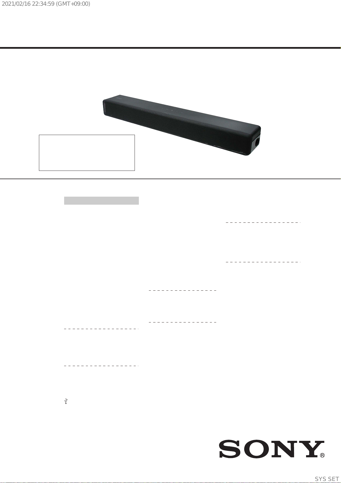
HT-S200F/SF200/SF201
2
1. SERVICING NOTES ............................................. 3
2. DISASSEMBLY
2-1. Disassembly Flow........................................................... 5
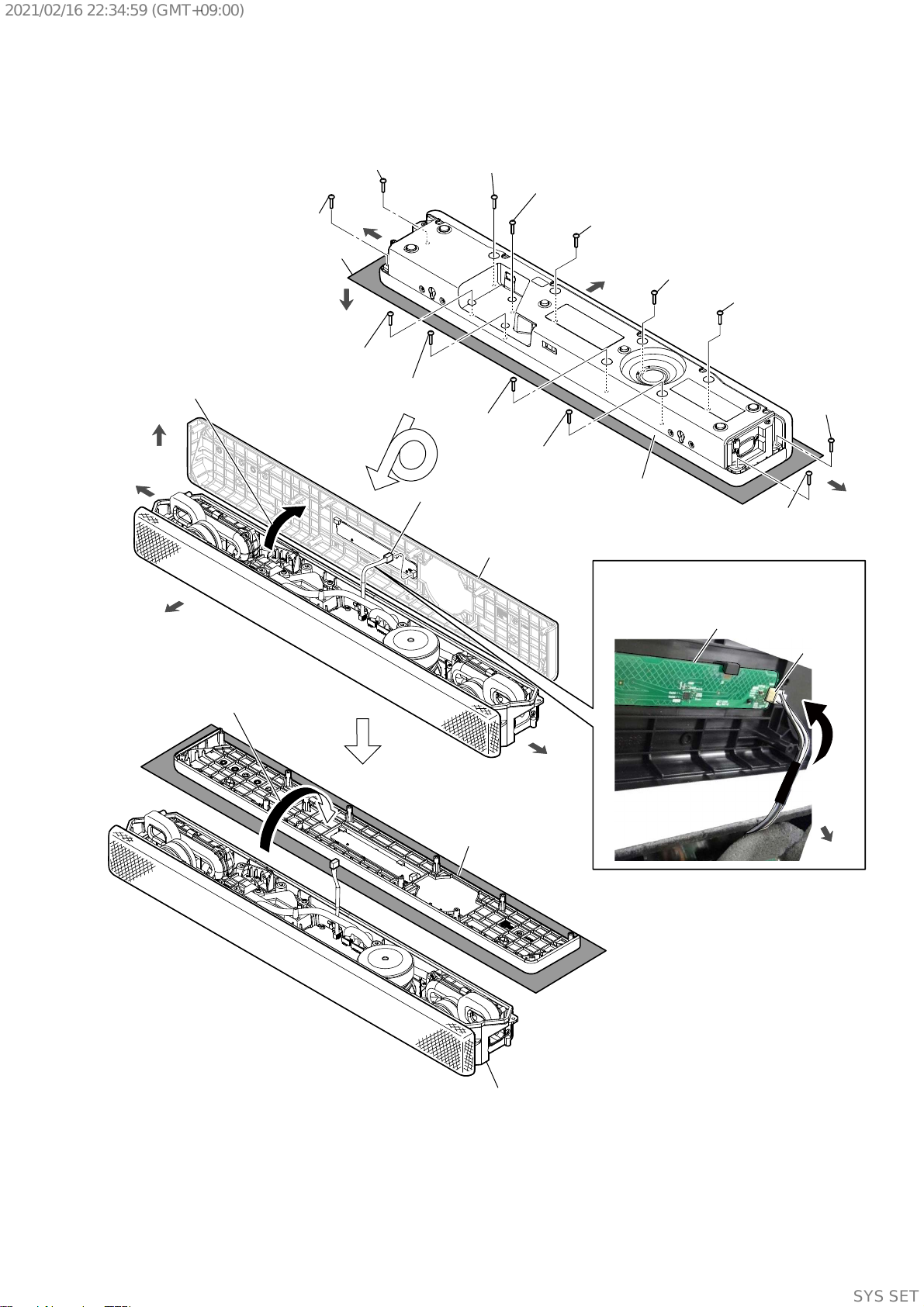
2-2. Side Panel (L)/(R)........................................................... 6
2-3. Cabinet (Top) Block, Cabinet (Bottom) Block ............... 7
2-4. TOUCH Board................................................................ 8
2-5. Punching Grille (VK)...................................................... 9
2-6. Front Panel Assy Block................................................... 10
2-7. Front Panel Assy, LED Board......................................... 11
2-8. Loudspeaker (70 mm) (Subwoofer)-1 ............................ 12
2-9. Loudspeaker (70 mm) (Subwoofer)-2 ............................ 13
2-10. Loudspeaker (46 mm) (Front L-ch Speaker)-1............... 14
2-11. Loudspeaker (46 mm) (Front L-ch Speaker)-2............... 15
2-12. Loudspeaker (46 mm) (Front R-ch Speaker).................. 16
2-13. Bluetooth Module ........................................................... 17
2-14. Cover (Connect) Assy..................................................... 17
2-15. USB Board...................................................................... 18
2-16. MAIN Board Block ........................................................ 19
2-17. MAIN Board ................................................................... 20
2-18. MAIN Board Service Position........................................ 21
3. TEST MODE ............................................................ 22
4. TROUBLESHOOTING .......................................... 28
5. DIAGRAMS
5-1. Block Diagram - MAIN Section -................................... 31
5-2. Block Diagram
- PANEL/POWER SUPPLY Section -............................ 32
5-3. Printed Wiring Board - MAIN Board -........................... 34
5-4. Schematic Diagram - MAIN Board (1/5) -..................... 35
5-5. Schematic Diagram - MAIN Board (2/5) -..................... 36
5-6. Schematic Diagram - MAIN Board (3/5) -..................... 37
5-7. Schematic Diagram - MAIN Board (4/5) -..................... 38
5-8. Schematic Diagram - MAIN Board (5/5) -..................... 39
5-9. Printed Wiring Board - USB Board -.............................. 40
5-10. Schematic Diagram - USB Board -................................. 40
5-11. Printed Wiring Board - LED Board -.............................. 40
5-12. Schematic Diagram - LED Board -................................. 40
6. EXPLODED VIEWS
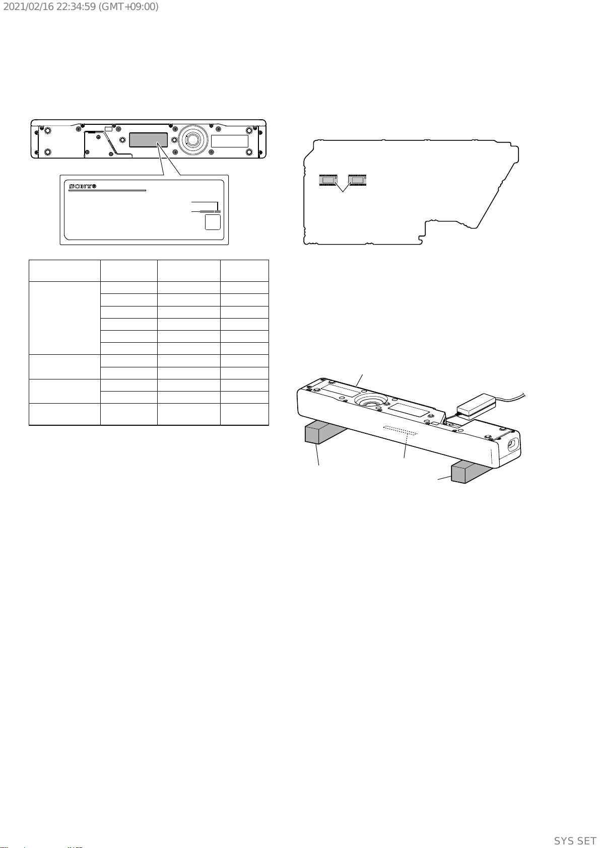
6-1. Foot, Top Cabinet Section............................................... 46
6-2. Front Panel Section......................................................... 47
6-3. MAIN Board Section ...................................................... 48
6-4. Front Speaker Section..................................................... 49
7. ELECTRICAL PARTS LIST .............................. 50
Accessories are given in the last of the electrical parts list.
TABLE OF CONTENTS
NOTES ON CHIP COMPONENT REPLACEMENT
• Never reuse a disconnected chip component.
• Notice that the minus side of a tantalum capacitor may be dam-
aged by heat.
SAFETY-RELATED COMPONENT WARNING!
COMPONENTS IDENTIFIED BY MARK 0OR DOTTED LINE
WITH MARK 0ON THE SCHEMATIC DIAGRAMS AND IN
THE PARTS LIST ARE CRITICAL TO SAFE OPERATION.
REPLACE THESE COMPONENTS WITH SONY PARTS
WHOSE PART NUMBERS APPEAR AS SHOWN IN THIS
MANUAL OR IN SUPPLEMENTS PUBLISHED BY SONY.
This system incorporates Dolby* Digital.
* Manufactured under license from Dolby
Laboratories.
Dolby, Dolby Audio and the double-D
symbol are trademarks of Dolby
Laboratories.
The BLUETOOTH®word mark and logos are
registered trademarks owned by Bluetooth
SIG, Inc. and any use of such marks by Sony
Corporation is under license. Other
trademarks and trade names are those of
their respective owners.
This system incorporates High-Denition
Multimedia Interface (HDMI™) technology.
The terms HDMI and HDMI High-Denition
Multimedia Interface, and the HDMI Logo
are trademarks or registered trademarks of
HDMI Licensing Administrator, Inc. in the
United States and other countries.
“BRAVIA” logo is a trademark of Sony
Corporation.
“ClearAudio+” is a trademark of Sony
Corporation.
“PlayStation” is a registered trademark or
trademark of Sony Interactive
Entertainment Inc.
MPEG Layer-3 audio coding technology
and patents licensed from Fraunhofer IIS
and Thomson.
Windows Media is either a registered
trademark or trademark of Microsoft
Corporation in the United States and/or
other countries.
This product is protected by certain
intellectual property rights of Microsoft
Corporation. Use or distribution of such
technology outside of this product is
prohibited without a license from Microsoft
or an authorized Microsoft subsidiary.
All other trademarks are trademarks of
their respective owners.
Copyrights and Trademarks
ATTENTION AU COMPOSANT AYANT RAPPORT
À LA SÉCURITÉ!
LES COMPOSANTS IDENTIFIÉS PAR UNE MARQUE 0SUR
LES DIAGRAMMES SCHÉMATIQUES ET LA LISTE DES
PIÈCES SONT CRITIQUES POUR LA SÉCURITÉ DE FONC-
TIONNEMENT. NE REMPLACER CES COMPOSANTS QUE
PAR DES PIÈCES SONY DONT LES NUMÉROS SONT DON-
NÉS DANS CE MANUEL OU DANS LES SUPPLÉMENTS
PUBLIÉS PAR SONY.
Ver. 1.2
Design and specications are subject to
change without notice.
Bar Speaker (1)
Remote control (1)
AC plug adaptor(1) (S200F: LA)
Optical digital cable (1)
AC adapter (1)
What’s in the Box
R03 (size AAA) battery (2)
AC power cord (mains lead) (1)
Cushion pads for wall mounting (2)
Operating Instructions
Startup Guide
WALL MOUNT TEMPLATE (1)
One of the following AC adapters is
included.
ACDP-085E03
Manufacturer’s name or trade mark
Sony Corporation
Commercial registration number
5010401067252
Address
1-7-1 Konan Minato-ku Tokyo, 108-
0075 Japan
Model identifier
ACDP-085E03
Input voltage
100 V -240 V
Input AC frequency
50 Hz /60 Hz
Output voltage - Output current - Output
power
19.5 Vdc - 4.36 A - 85.0 W
Average active eciency
88.0%
Eciency at low load (10 %)
88.2%
No-load power consumption
0.21 W
ACDP-120M01
Manufacturer’s name or trade mark
Sony Corporation
Commercial registration number
5010401067252
Address
1-7-1 Konan Minato-ku Tokyo, 108-
0075 Japan
Model identifier
ACDP-120M01
Input voltage
100 V -240 V
Input AC frequency
50 Hz /60 Hz
Output voltage - Output current - Output
power
19.5 Vdc - 6.2 A - 120.9 W
Average active eciency
88.0%
Eciency at low load (10 %)
88.2%
No-load power consumption
0.21 W
AC adaptor (SF200)
SYSSET
2021/02/1622:34:59(GMT+09:00)