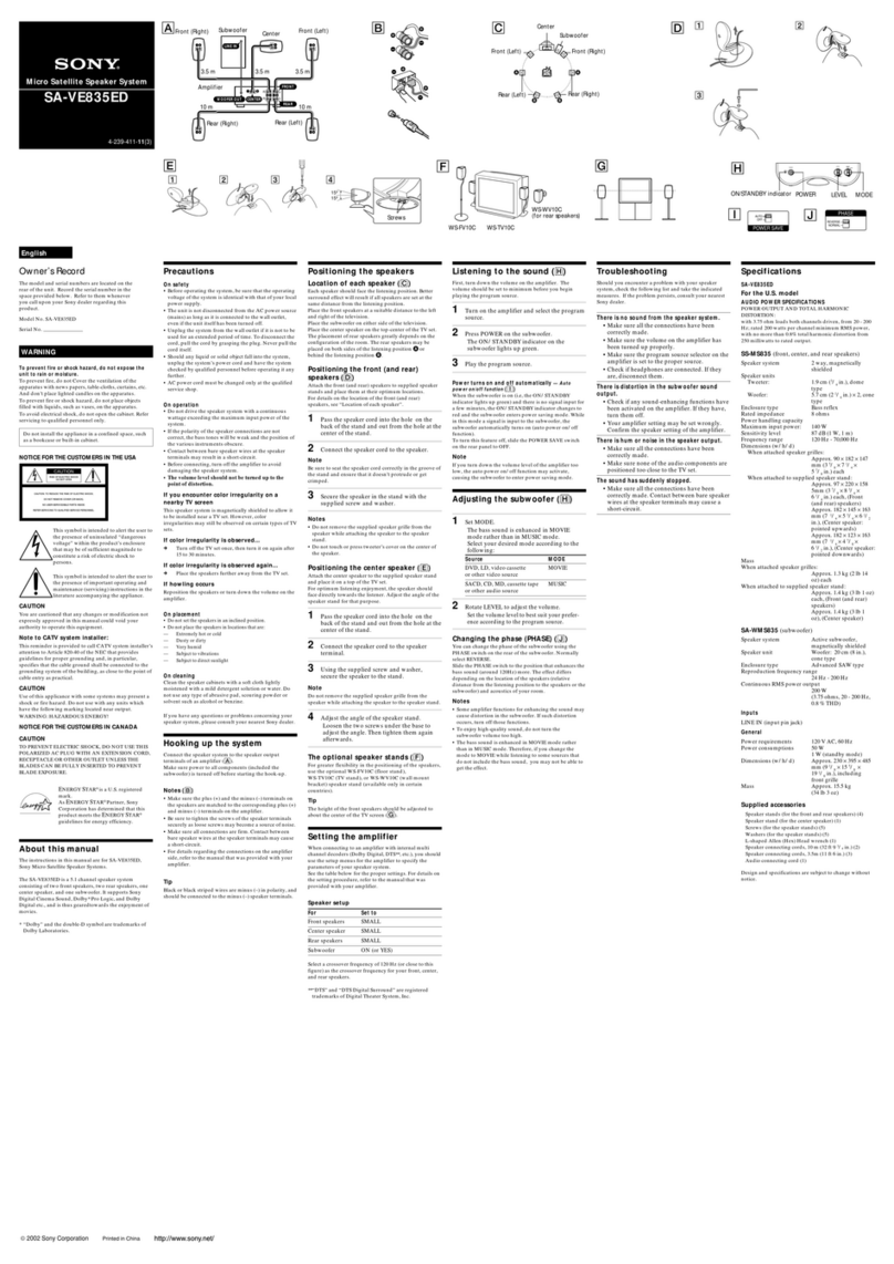
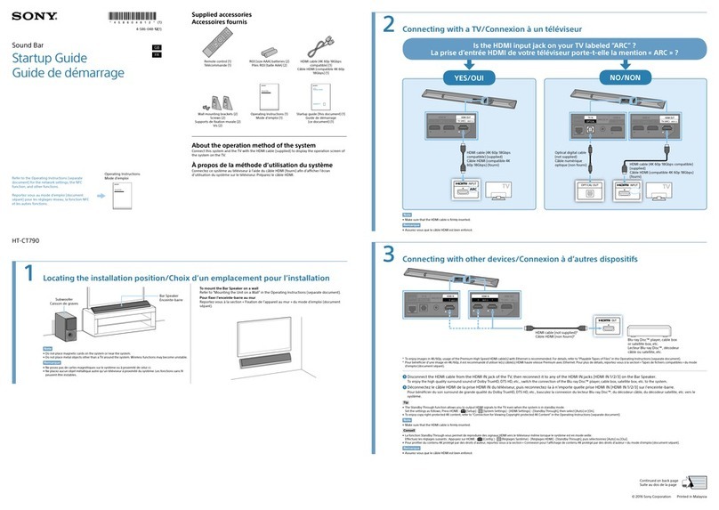
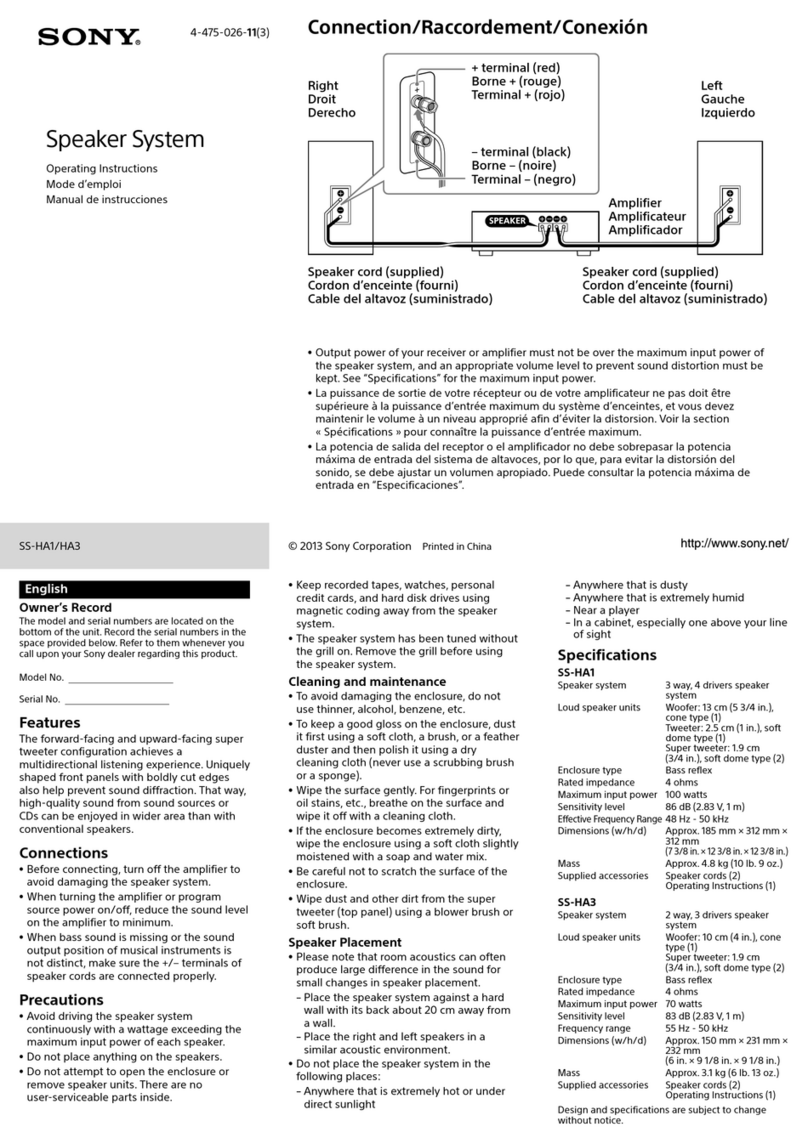
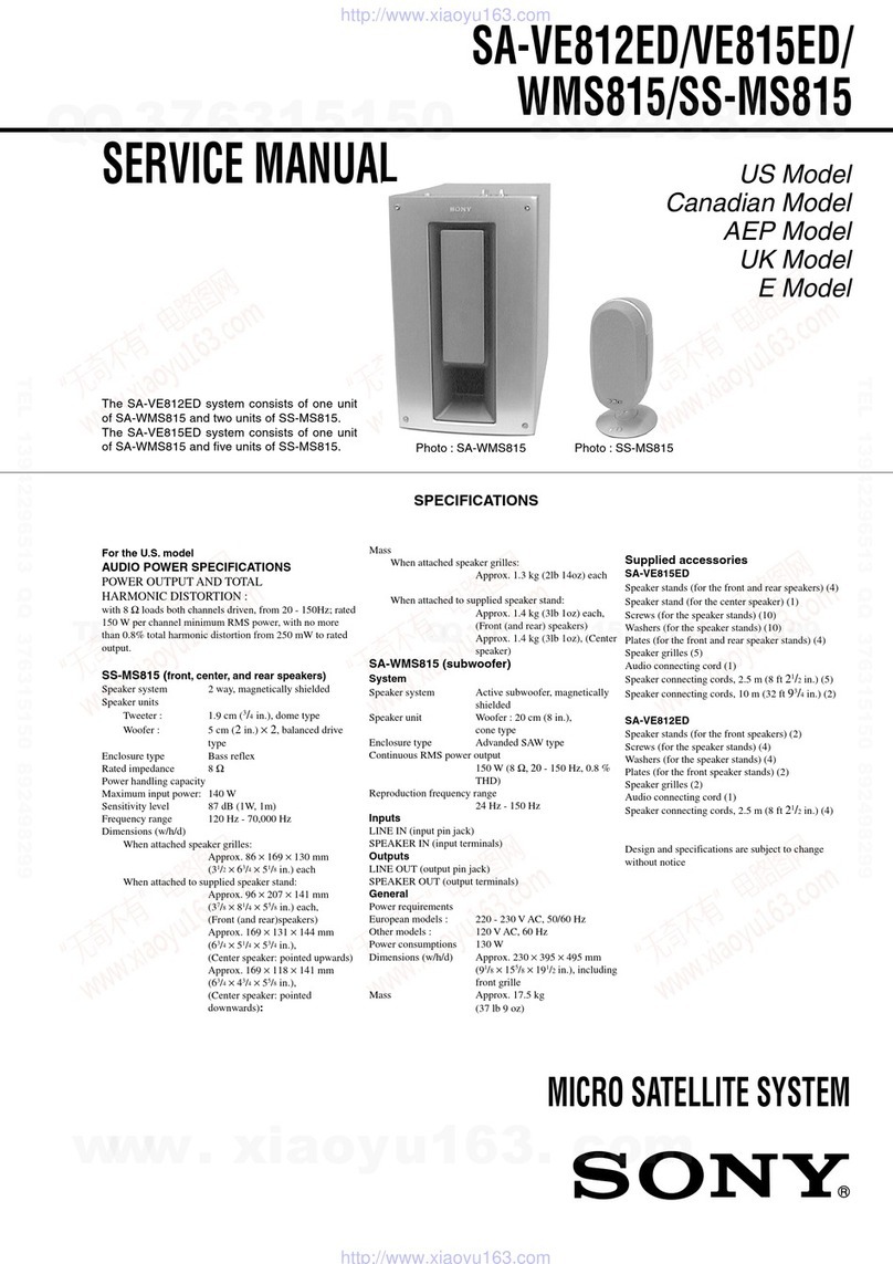
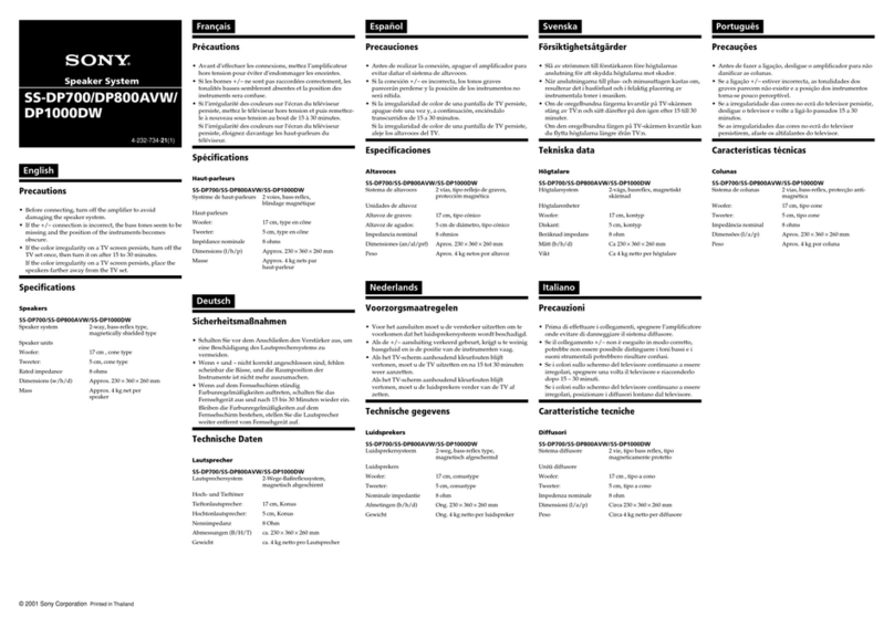
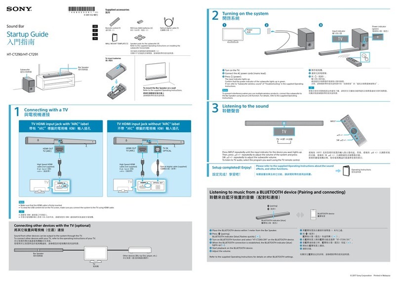
Sony SA-TSLF1H User manual

SERVICE MANUAL
Sony Corporation
Home Audio Division
Published by SonyTechno Create Corporation
US Model
Canadian Model
AEP Model
UK Model
E Model
Australian Model
Chinese Model
SPEAKER SYSTEM
9-887-284-03
2006J16-1
© 2006.10
Ver. 1.2 2006.10
SPECIFICATIONS
SA-TSLF1H/SS-CTLF1H/
TSLF1H/TSLF1HW
•SA-TSLF1H is surround speaker system (L)
in DAV-LF1H.
•SS-CTLF1H is center speaker system
in DAV-LF1H.
•SS-TSLF1H is front speaker system
in DAV-LF1H.
•SS-TSLF1HW is surround speaker system
(R) in DAV-LF1H.
Speakers
Front
Speaker system Closed, magnetically
shielded
Speaker unit Woofer: 70 ×120 mm
(2
7
/
8
× 4
3
/
4
inches) cone
type
Tweeter: 25 mm (1 inch)
dome type
Rated impedance 4 ohms
Dimensions (approx.) 105 ×705 × 35 mm
(4
1
/
4
×27
7
/
8
×1
7
/
16
inches)
(w/h/d)
302 ×1,300 (max) ×
302 mm
(12 ×51
1
/
4
(max) ×
12 inches)
(w/h/d) with stand
Mass (approx.) 2.1 kg (4 lb 11 oz)
5.9 kg (13 lb 1 oz) with
stand
Surround (R)
Speaker system Closed, magnetically
shielded
Speaker unit Woofer: 70 ×120 mm
(2
7
/
8
×4
3
/
4
inches) cone
type
Tweeter: 25 mm (1 inch)
dome type
Rated impedance 3.5 ohms
Dimensions (approx.) 105 ×705 ×35 mm
(4
1
/
4
×27
7
/
8
×1
7
/
16
inches)
(w/h/d)
302 ×1,300 (max) ×
302 mm
(12 ×51
1
/
4
(max) ×
12 inches)
(w/h/d) with stand
Mass (approx.) 2.0 kg (4 lb 7 oz)
5.8 kg (12 lb 13 oz) with
stand
Surround (L)
Speaker system Closed, magnetically
shielded
Speaker unit Woofer: 70 ×120 mm
(2
7
/
8
×4
3
/
4
inches) cone
type
Tweeter: 25 mm (1 inch)
dome type
Rated impedance 3.5 ohms
Dimensions (approx.) 105 ×705 ×35 mm
(4
1
/
4
×27
7
/
8
×1
7
/
16
inches)
(w/h/d)
302 ×1,300 (max) ×
302 mm
(12 ×51
1
/
4
(max) ×
12 inches)
(w/h/d) with stand
Mass (approx.) 2.5 kg (5 lb 9 oz)
6.3 kg (13 lb 15 oz) with
stand
Center
Speaker system Closed, magnetically
shielded
Speaker unit Woofer: 70 ×120 mm
(2
7
/
8
×4
3
/
4
inches) dia.
cone type
Tweeter: 25 mm
(1 inch) dome type
Rated impedance 4.0 ohms
Dimensions (approx.) 545 ×105 ×35 mm
(21
1
/
2
×4
1
/
4
× 1
7
/
16
inches)
(w/h/d)
545 ×116 ×60 mm
(21
1
/
2
×4
5
/
8
×2
3
/
8
inches)
(w/h/d) with stand
Mass (approx.) 1.9 kg (4 lb 4 oz)
2.1 kg (4 lb 11 oz) with
stand
Design and specifications are subject to change
without notice.
(SS-TSLF1H)
(SS-TSLF1HW)
(SA-TSLF1H)
(SS-CTLF1H)
SA-TSLF1H
SS-TSLF1H SS-CTLF1H SS-TSLF1HW

2
SA-TSLF1H/SS-CTLF1H/TSLF1H/TSLF1HW
TABLE OF CONTENTS
1. SERVICING NOTES ................................................ 3
2. GENERAL ................................................................... 7
3. DISASSEMBLY (SA-TSLF1H)
3-1. Disassembly Flow ........................................................... 8
3-2. Grille Frame (A) Assy ..................................................... 8
3-3. Loudspeaker (7 x 12 cm) (SP901)................................... 9
3-4. Bracket (A) Terminal....................................................... 9
3-5. Loudspeaker (2.5 cm) (SP902), DIAT PD Board............ 10
3-6. DIAT AMP Board............................................................ 11
3-7. Partition ........................................................................... 11
4. DISASSEMBLY (SS-CTLF1H)
4-1. Disassembly Flow ........................................................... 12
4-2. Grille Frame (C) Assy ..................................................... 12
4-3. Loudspeaker (7 x 12 cm) (SP901)................................... 13
4-4. Loudspeaker (2.5 cm) (SP902)........................................ 13
4-5. MOUNTED PC Board .................................................... 14
5. DISASSEMBLY (SS-TSLF1H/TSLF1HW)
5-1. Disassembly Flow ........................................................... 15
5-2. Grille Frame (P) Assy ...................................................... 15
5-3. Loudspeaker (7 x 12 cm) (SP901)................................... 16
5-4. Loudspeaker (2.5 cm) (SP902)........................................ 16
5-5. Partition ........................................................................... 17
5-6. MOUNTED PC Board .................................................... 18
6. DIAGRAMS
6-1. Block Diagram ................................................................ 20
6-2. Printed Wiring Board — DIAT PD Board —.................. 21
6-3. Schematic Diagram — DIAT PD Board — .................... 22
6-4. Printed Wiring Board — DIAT AMP Board — .............. 23
6-5. Schematic Diagram — DIAT AMP Board (1/4) — ........ 24
6-6. Schematic Diagram — DIAT AMP Board (2/4) — ........ 25
6-7. Schematic Diagram — DIAT AMP Board (3/4) — ........ 26
6-8. Schematic Diagram — DIAT AMP Board (4/4) — ........ 27
6-9. Printed Wiring Boards — LED Board,
RETAINER Board, SPK JACK Board — ....................... 28
6-10. Schematic Diagram — LED Board,
RETAINER Board, SPK JACK Board — ....................... 29
7. EXPLODEDVIEWS
7-1. Overall Section (SA-TSLF1H)........................................ 36
7-2. Overall Section (SS-CTLF1H) ........................................ 37
7-3. Overall Section (SS-TSLF1H) ........................................ 38
7-4. Overall Section (SS-TSLF1HW)..................................... 39
8. ELECTRICAL PARTS LIST .................................. 40
Notes on chip component replacement
•Never reuse a disconnected chip component.
•Notice that the minus side of a tantalum capacitor may be
damaged by heat.
UNLEADED SOLDER
Boards requiring use of unleaded solder are printed with the lead-
free mark (LF) indicating the solder contains no lead.
(Caution: Some printed circuit boards may not come printed with
the lead free mark due to their particular size)
: LEAD FREE MARK
Unleaded solder has the following characteristics.
•Unleaded solder melts at a temperature about 40 °C higher
than ordinary solder.
Ordinary soldering irons can be used but the iron tip has to be
applied to the solder joint for a slightly longer time.
Soldering irons using a temperature regulator should be set to
about 350 °C.
Caution: The printed pattern (copper foil) may peel away if
the heated tip is applied for too long, so be careful!
•Strong viscosity
Unleaded solder is more viscou-s (sticky, less prone to flow)
than ordinary solder so use caution not to let solder bridges
occur such as on IC pins, etc.
•Usable with ordinary solder
It is best to use only unleaded solder but unleaded solder may
also be added to ordinary solder.
Ver. 1.1
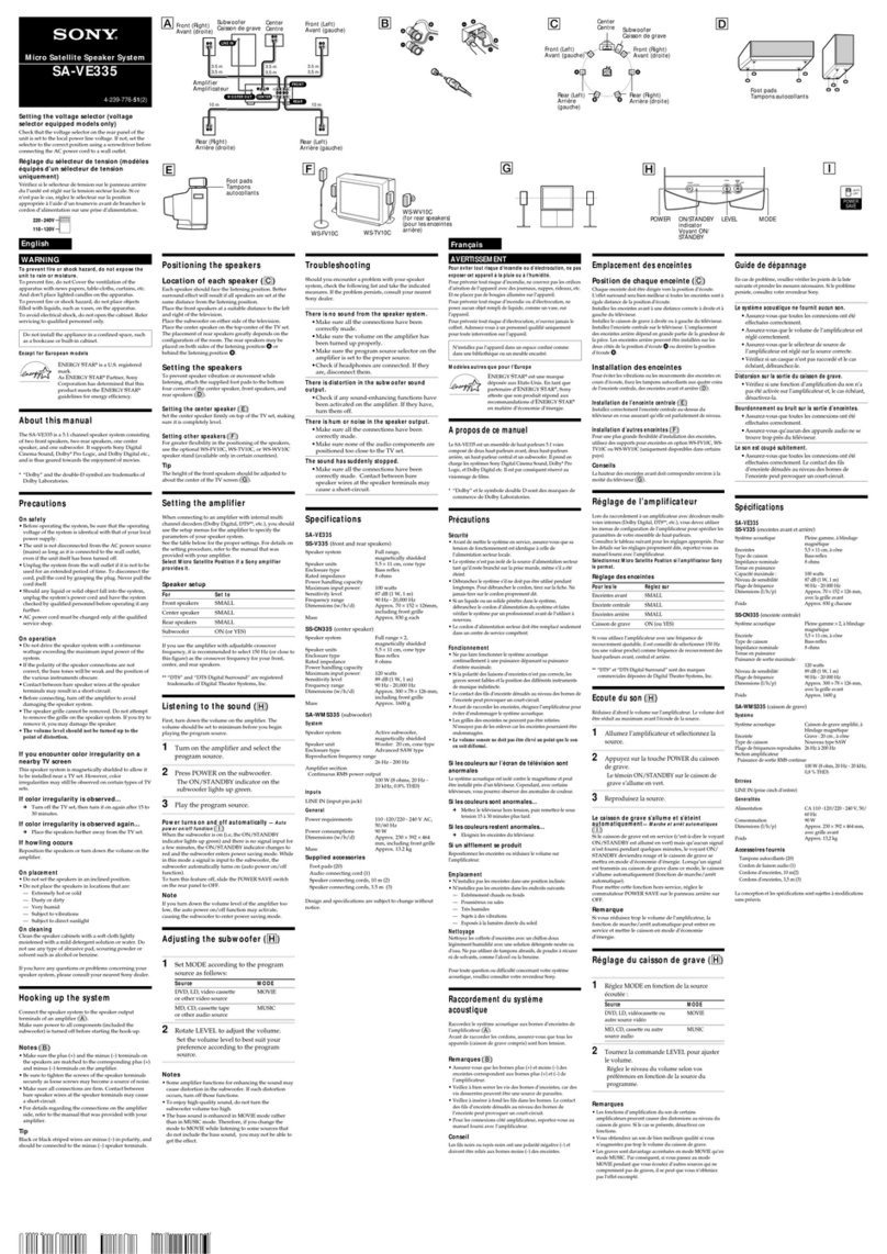
3
SA-TSLF1H/SS-CTLF1H/TSLF1H/TSLF1HW
SECTION 1
SERVICING NOTES
[AMP Board Input Signal Check Procedure]
Note 1: Connect the SA-WSLF1H to the HCD-LF1H. Set up the system so that the infrared signal from IR transmitter (DIR-T1) can be received by the
rear speaker (SA-TSLF1H).
Note 2: The IR status indicator of this unit (SA-TSLF1H) lights in red when the power of the SA-WSLF1H receiving waiting state (when data is not
transmitted.) When the power of the SA-WSLF1H is turned on and the infrared signal from IR transmitter (DIR-T1) is received by this unit (SA-
TSLF1H), the IR status indicator of this unit (SA-TSLF1H) lights in green.
Check procedure:
1. Connect a spectrum analyzer and an oscilloscope to the connector CN7301 pin-1 of DIAT PD board.
2. Confirm that the spectrum is displayed as shown in Fig. 1 on spectrum analyzer. Also confirm that the waveform as shown in Fig. 2
is displayed.
4.5MHz
↓
Fig. 1 Fig. 2
IR receiver diode (D7301-D7304)
DIAT PD board CN7301
1
pin
Infrared
Transmission
Spectrum analyzer
or Oscilloscope
IR transmitter
(DIR-T1)
Subwoofer
(SA-WSLF1H)
*In the case of DIR-R3 is connected, the connector CN7301 pin-1 of
DIAT PD board is checked.
SPK JACK
board
DIAT AMP
board
Refer to figure, and inspect the DIAT AMP board.
•SERVICING POSITION (DIAT AMP BOARD)

4
SA-TSLF1H/SS-CTLF1H/TSLF1H/TSLF1HW
The units that are required for the system operation check during repair service
Unit
required for checking
Unit to be
checked
DVD player:
HCD-LF1H
Subwoofer:
SA-WSLF1H
Front speaker:
SS-TSLF1H
Center speaker:
SS-CTLF1H
Surround speaker (L):
SA-TSLF1H
AC adaptor:
AC-LF1HR
Surround speaker (R):
SS-TSLF1HW
Remote commander:
RM-ADP011
DVD player:
HCD-LF1H Subwoofer:
SA-WSLF1H Front speaker:
SS-TSLF1H Center speaker:
SS-CTLF1H Surround speaker
(L): SA-TSLF1H AC adaptor:
AC-LF1HR Surround speaker
(R): SS-TSLF1HW
*1 Only the defective unit.
Units with
a
mark: The units that are required for the system operation check during repair service.
(However, there can be a case that some units of the system need to not be brought into repair shop depending on the unit.that become defective.)
*1
screw A
(+BVTP 3
×
14)
screw A
capacitor
two screws
(+BVTP 3
×
10)
PD block
[Note on Assembling the SA-TSLF1H]
When assembling the PD block, be sure to follow the steps below.
Otherwise, the capacitor may break and a product failure may result.
3. Install the LOUDSPEAKER (2.5 cm) (SP902) with the
+BVTP3 ×8 screw.
2. Take in the capacitor to the main unit.
Check that the capacitor does not touch screw A inside the
main unit.
1. Check that screwA is +BVTP3 ×14, and install the PD block
to the main unit.
four screws
(+BVTP 3
×
8)
LOUDSPEAKER (2.5cm) (SP902)
Ver. 1.1

5
SA-TSLF1H/SS-CTLF1H/TSLF1H/TSLF1HW
+
+
-
-
CN301 CN109 CN108 CN302 CN7301 CN310
CN311
CN307
CN305CN304
DIAT AMP
board
LED
board
DIAT PD
board
DIAT PD
board
SPK JACK
board
SPK JACK
board
RETAINER
board
CN308
loudspeaker
(7
×
12 cm) (SP901)
loudspeaker
(7
×
12 cm) (SP901)
loudspeaker
(2.5 cm) (SP902)
loudspeaker
(2.5 cm) (SP902)
DIAT AMP
board
-
+
-
+
-
+
+
+
+
-
+
+
+
-
--
-
-
IN TW
gray blue
red
WF
MOUNTED PC board
MOUNTED PC board
loudspeaker
(7
×
12 cm) (SP901)
loudspeaker
(7
×
12 cm) (SP901)
loudspeaker
(2.5 cm) (SP902)
loudspeaker
(2.5 cm) (SP902)
•CHART OF HARNESSES
•SA-TSLF1H
•SS-CTLF1H

6
SA-TSLF1H/SS-CTLF1H/TSLF1H/TSLF1HW
+
-
+
-
+
-
loudspeaker
(2.5 cm) (SP902)
loudspeaker
(2.5 cm) (SP902)
loudspeaker
(7
×
12 cm) (SP901)
loudspeaker
(7
×
12 cm) (SP901)
+
-
+
-
+
-
loudspeaker
(7
×
12 cm) (SP901)
loudspeaker
(7
×
12 cm) (SP901)
loudspeaker
(2.5 cm) (SP902)
acoustic material
loudspeaker
(2.5 cm) (SP902)
•SS-TSLF1H
•SS-TSLF1HW

7
SA-TSLF1H/SS-CTLF1H/TSLF1H/TSLF1HW
SECTION 2
GENERAL This section is extracted
from instruction manual.
Surround speaker (L)
AIR receiver (29)
BIR status indicator (29)

8
SA-TSLF1H/SS-CTLF1H/TSLF1H/TSLF1HW
3-2. GRILLE FRAME (A) ASSY
Note: Follow the disassembly procedure in the numerical order given.
SECTION 3
DISASSEMBLY (SA-TSLF1H)
3-1. DISASSEMBLY FLOW
•This set can be disassembled in the order shown below.
3-3. LOUDSPEAKER
(7
×
12 cm) (SP901)
(Page 9)
3-4. BRACKET (A)
TERMINAL (Page 9) 3-5. LOUDSPEAKER
(2.5 cm) (SP902),
DIAT PD BOARD
(Page 10)
3-6. DIAT AMP BOARD
(Page 11)
3-7. PARTITION
(Page 11)
3-2. GRILLE FRAME (A) ASSY
(Page 8)
SET
cushion
Remove the grille frame (A) assy in the direction of the arrow
A
.
2
grille frame (A) assy
driver
A
1
Ver. 1.1

9
SA-TSLF1H/SS-CTLF1H/TSLF1H/TSLF1HW
+
+
-
-
1
four
screws
(+BVTP 3
×
10)
3
loudspeaker
(7
×
12 cm)
(SP901)
2
harnesses
terminals
Bend down the terminals before installation
as shown in the figure.
3-3. LOUDSPEAKER (7 x 12 cm) (SP901)
1
two
screws
(+BVTP 3
×
14)
3
bracket (A) terminal
2
six
screws
(+BVTP 3
×
10)
3-4. BRACKET (A)TERMINAL
Ver. 1.1

10
SA-TSLF1H/SS-CTLF1H/TSLF1H/TSLF1HW
3-5. LOUDSPEAKER (2.5 cm) (SP902), DIAT PD BOARD
+
+
–
–5
two screws
(+BVTP 3
×
10)
7
PD window assy
6
two claws
qd
LED board
qk
PD bracket
ql
DIAT PD board
q;
PD cushion
qj
RETAINER board
qa
screw
(+BVTP 3
×
10)
qh
three screws
(+BVTP 3
×
10)
8
screw
(+BVTP 3
×
14)
2
Take out the capacitor.
9
two screws
(+BVTP 3
×
10)
When removing the PD block, be sure to remove the
LOUDSPEAKER (2.5 cm) (SP902), and take the
capacitor out of the main unit.
The capacitor may break if the PD block is not properly
assembled. Be sure to refer to [Note on Assembling
the SA-TSLF1H] in the Service Note.
qs
connector
(CN311)
qf
connector
(CN7301)
qg
connector
(CN310)
1
four screws
(+BVTP 3
×
8)
4
loudspeaker
(2.5 cm)
(SP902)
3
harnesses
PRECAUTION DURING PD BLOCK REMOVING
Ver. 1.1

11
SA-TSLF1H/SS-CTLF1H/TSLF1H/TSLF1HW
3
connector
(CN109)
4
connector
(CN108)
5
connector
(CN302)
8
connector
(CN305)
9
connector
(CN304)
7
connector
(CN308)
6
connector
(CN301)
0
four
screws
(+BVTP 3
×
6)
qf
DIAT AMP board
qa
two
screws
(+BVTP 3
×
6)
qd
qs
2
amp cover
1
six
screws
(+BVTP 3
×
10)
3-6. DIAT AMP BOARD
3-7. PARTITION
1
two
screws
(+BVTP 3
×
10)
5
baffle board (A)
4
eight
screws
(+BVTP 3
×
10)
7
partition
Attention the position
of capacitor.
6
Remove the partition in
the direction of the arrow.
2
two claws
3
PD window assy

12
SA-TSLF1H/SS-CTLF1H/TSLF1H/TSLF1HW
4-2. GRILLE FRAME (C) ASSY
Note: Follow the disassembly procedure in the numerical order given.
SECTION 4
DISASSEMBLY (SS-CTLF1H)
4-1. DISASSEMBLY FLOW
•This set can be disassembled in the order shown below.
4-3. LOUDSPEAKER
(7
×
12 cm)
(SP901)
(Page 13)
4-4. LOUDSPEAKER
(2.5 cm)
(SP902)
(Page 13)
4-5. MOUNTED PC BOARD
(Page 14)
4-2. GRILLE FRAME (C) ASSY
(Page 12)
SET
cushion
1
Remove the grille frame (C) assy in the direction of the arrow
A
.
2
grille frame (C) assy
driver
A

13
SA-TSLF1H/SS-CTLF1H/TSLF1H/TSLF1HW
4-3. LOUDSPEAKER (7 x 12 cm) (SP901)
4-4. LOUDSPEAKER (2.5 cm) (SP902)
+
-
+
-
1
four
screws
(+BVTP 3
×
10)
3
loudspeaker
(7
×
12 cm)
(SP901)
2
harnesses
terminals
Bend down the terminals before installation
as shown in the figure.
+
+
-
-
1
four
screws
(+BVTP 3
×
10)
3
loudspeaker
(2.5 cm)
(SP902)
2
harnesses

14
SA-TSLF1H/SS-CTLF1H/TSLF1H/TSLF1HW
4-5. MOUNTED PC BOARD
-
+
-
+
-
+
1
four
screws
(+BVTP 3
×
10)
2
f
our
screws
(+BVTP 3
×
8)
5
mounted pc board
4
Remove soldering from
the six points.
3
network bracket
IN TW blue
gray
red
WF

15
SA-TSLF1H/SS-CTLF1H/TSLF1H/TSLF1HW
5-2. GRILLE FRAME (P) ASSY
Note: Follow the disassembly procedure in the numerical order given.
SECTION 5
DISASSEMBLY (SS-TSLF1H/TSLF1HW)
5-1. DISASSEMBLY FLOW
•This set can be disassembled in the order shown below.
5-3. LOUDSPEAKER
(7
×
12 cm)
(SP901)
(Page 16)
5-4. LOUDSPEAKER
(2.5 cm)
(SP902)
(Page 16)
5-5. P
ARTITION
(Page 17)
SS-TSLF1H
5-6. MOUNTED PC BOARD
(Page 18)
5-2. GRILLE FRAME (P) ASSY
(Page 15)
SET
cushion
2
grille frame (P) assy
driver
1
Remove the grille frame (P) assy in the direction of the arrow.

16
SA-TSLF1H/SS-CTLF1H/TSLF1H/TSLF1HW
5-3. LOUDSPEAKER (7 x 12 cm) (SP901)
5-4. LOUDSPEAKER (2.5 cm) (SP902)
+
-
+
-
1
four
screws
(+BVTP 3
×
10)
3
loudspeaker
(7
×
12 cm)
(SP901)
2
harnesses
terminals
Bend down the terminals before installation
as shown in the figure.
+
+
-
-
1
four
screws
(+BVTP 3
×
10)
3
loudspeaker
(2.5 cm)
(SP902)
2
harnesses

17
SA-TSLF1H/SS-CTLF1H/TSLF1H/TSLF1HW
5-5. PARTITION
1
two
screws
(+BVTP 3
×
14)
2
six
screws
(+BVTP 3
×
10)
3
four
screws
(+BVTP 3
×
10)
SS-TSLF1HW
SS-TSLF1HW
SS-TSLF1H
4
four
screws
(+BVTP 3
×
10)
5
eight
screws
(+BVTP 3
×
10)
7
partition
To the loudspeaker
(2.5 cm) (SP902)
capacitor
acoustic
material
6
Remove the partition in the
direction of the arrow.
1
two
screws
(+BVTP 3
×
14)
2
six
screws
(+BVTP 3
×
10)
SS-TSLF1HW
Attention the position of capacitor.
When assembling it, please put
capacitor on acoustic material.
*
*

18
SA-TSLF1H/SS-CTLF1H/TSLF1H/TSLF1HW
5-6. MOUNTED PC BOARD
(SS-TSLF1H)
-
+
-
+
-
+
1
four
screws
(+BVTP 3
×
10)
2
f
our
screws
(+BVTP 3
×
8)
5
mounted pc board
4
Remove soldering from
the six points.
3
network bracket
IN TW blue
gray
red
WF

1919
SA-TSLF1H/SS-CTLF1H/TSLF1H/TSLF1HW
•Waveforms
– DIAT AMP Board –
1
IC102
r;
(OSC1)
2
IC107
wd
(X1)
3
IC301
rk
(XFSOIN)
1 V/DIV, 40 ns/DIV
81.4 ns
3.0 Vp-p
1 V/DIV, 100 ns/DIV
125 ns
3.8 Vp-p
1 V/DIV, 10 ns/DIV
20.3 ns
3.2 Vp-p
Note on Schematic Diagrams:
•All capacitors are in µF unless otherwise noted. (p: pF)
50WV or less are not indicated except for electrolytics and
tantalums.
•All resistors are in Ωand 1/4W or less unless otherwise
specified.
•C: panel designation.
•A: B+ Line.
•Voltages and waveforms are dc with respect to ground
under no-signal (detuned) conditions.
•Voltages are taken with aVOM (Input impedance 10 MΩ).
Voltage variations may be noted due to normal production
tolerances.
•Waveforms are taken with a oscilloscope.
Voltage variations may be noted due to normal production
tolerances.
•Circled numbers refer to waveforms.
•Signal path.
F: AUDIO
Note on Printed Wiring Boards:
•X: parts extracted from the component side.
•Y: parts extracted from the conductor side.
•: Pattern from the side which enables seeing.
(The other layers' patterns are not indicated.)
•Indication of transistor.
• Note for PrintedWiring Boards and Schematic Diagrams
Caution:
Pattern face side: Partsonthepattern faceside seenfrom
(Side B) the pattern face are indicated.
Parts face side: Parts on the parts face side seen from
(Side A) the parts face are indicated.
C
BThese are omitted.
E
Q
SECTION 6
DIAGRAMS
•Circuit Boards Location
DIAT PD
board
LED
board
RETAINER
board
DIAT AMP
board
SPK JACK
board

2020
SA-TSLF1H/SS-CTLF1H/TSLF1H/TSLF1HW
6-1. BLOCK DIAGRAM
• Signal Path
: AUDIO
IC7301
ANALOG AGC
16
OUT
3SIS
D7304
+2.5V
5IN
IC302
SELECTOR
7
OUT
3INT2
1INT1
2SW1
4SW2
IC102
RF DEMODULATOR
A/D CONVERTER
IC109
LEVEL SHIFT IC301
STREAM PROCESSOR
IC100
POWER DRIVER
10 ADVIN
X101
12.288MHz
40 OSCI
43 OSCO
35 SWDT
36 XSCEN
SWDT
13 XRST
XSCEN
37 SCLK
SCLK
38 SCMODE
SCMODE
34 RDT
SRDT
33 CSDB
CSDB
61 DTVALID
DTVALID
54
BCK/RCLK
3
1
2
60
DAOUT/ROUT
6
4
5
59
LRCK/RCS
8
9
10
31
APX
11
12
13
30 BCK
31 DATA
29 LRCK
36 XFSIIN
18 NSPMUTE
NSPMUTE
19 SOFTMUTE
SOFTMUTE
20 PGMUTE
PGMUTE
21 SCDT
SCDT
22 SCSHIFT
SCSHIFT
23 SCLATCH
48 XFSOIN
27 INIT
SCLATCH
2
4
IC3051
OSC
X3051
49.1MHz
3OTW
OTW
4SD
SD
5RESET
RST
6PWM_A
14 PWM_B
28
I
30
OUT_A
25
I
27
OUT_B
11
OUTL1
9
OUTL2
IC200
POWER DRIVER
3OTW
OTW
4SD
SD
5RESET
RST
6PWM_A
14 PWM_B
28
I
30
OUT_A
25
I
27
OUT_B
6
OUTR1
4
OUTR2
(+)
(-)
Q110, 111
OVER LOAD DETECT
CN304
SP901
(WOOFER)
SP902
(TWEETER)
(+)
(–)
Q210, 211
OVER LOAD DETECT
IC103
LEVEL SHIFT
8
910
6
4 5
11
12 13
3
1 2
IC106
LEVEL SHIFT
IC107
SYSTEM CONTROLLER
6
54
8
109
11
1312
SWDT
SRDT
XSCEN
SCLK
SCMODE
CSDB
DTVALID
NSPMUTE
SOFTMUTE
PGMUTE
SCDT
SCSHIFT
SCLATCH
OTW
OCP
RST
35
DAMP_NSPMUTE
26
XRST_INIT
34
DAMP_SOFTMUTE
33
DAMP_PGMUTE
61
DAMP_SCDT
60
DAMP_SHIFT
59
DAMP_LATCH
39
DRIVE_OTW
38
DRIVE_OCP
37
DRIVE_RST
14
DTVALID
15
CSDB
53
DIAT SRDT
48
SCMODE
51
DIAT SCLK
50
XSCEN
52
DIAT SWDT
22 XO
23 XI
19 RESET
17 AC CUT
42 LED_RED
X102
8MHz
Q3551
PROTECT DETECT
Q305
SWITCH
Q308
SWITCH
LED
RED
IC105
RESET
1
2
+5V
+3.3V
Q306, 309
LED DRIVER
41 LED_GREEN
58 V_CONT
57 MAIN_OFF
LED
GREEN
Q307, 310
LED DRIVER
D7303
D7302
(IR RECEIVER)
D7301
Q301-303
SELECTOR
Q7301, 7302
AMP
V-CONT
AC-CUT
MAIN-OFF
+1.5V IC101
+1.5V REG
+2.5V IC104
+2.5V REG
+5V
IC108
+3.3V REG
+1.8V
+3.3V
IC113
+1.8V REG
+2.5V
+12V
IC7302
+2.5V REG
T101
SPEAKER TERMINAL
(TO AC-LF1HR)
TO
SURROUND SPEAKER (R)
(
(
SPEAKER SYSTEM
COARD
1
2
3
1
2
1
2
3
4
5
CN109
CN108
CN302
IC110
+5V REG
IC111
+12V REG
(IR STATUS INDICATOR)
This manual suits for next models
3
Table of contents
Other Sony Speakers System manuals

Sony
Sony SS-XB3A Instruction Manual

Sony
Sony SRS-Z500 User manual

Sony
Sony HT-CT290 User manual

Sony
Sony SRS-A37 User manual

Sony
Sony HT-ST5 User manual

Sony
Sony HT-S200F User manual

Sony
Sony SS-MF450H Quick start guide

Sony
Sony XDP-PK1000 User manual

Sony
Sony SRS-P7 - Portable Speakers User manual

Sony
Sony HT-MT300 User guide