manuals.online logo
Brands
  1. Home
  2. •
  3. Brands
  4. •
  5. Sony
  6. •
  7. TV
  8. •
  9. Sony Trinitron KV-27V20 User manual

Sony Trinitron KV-27V20 User manual

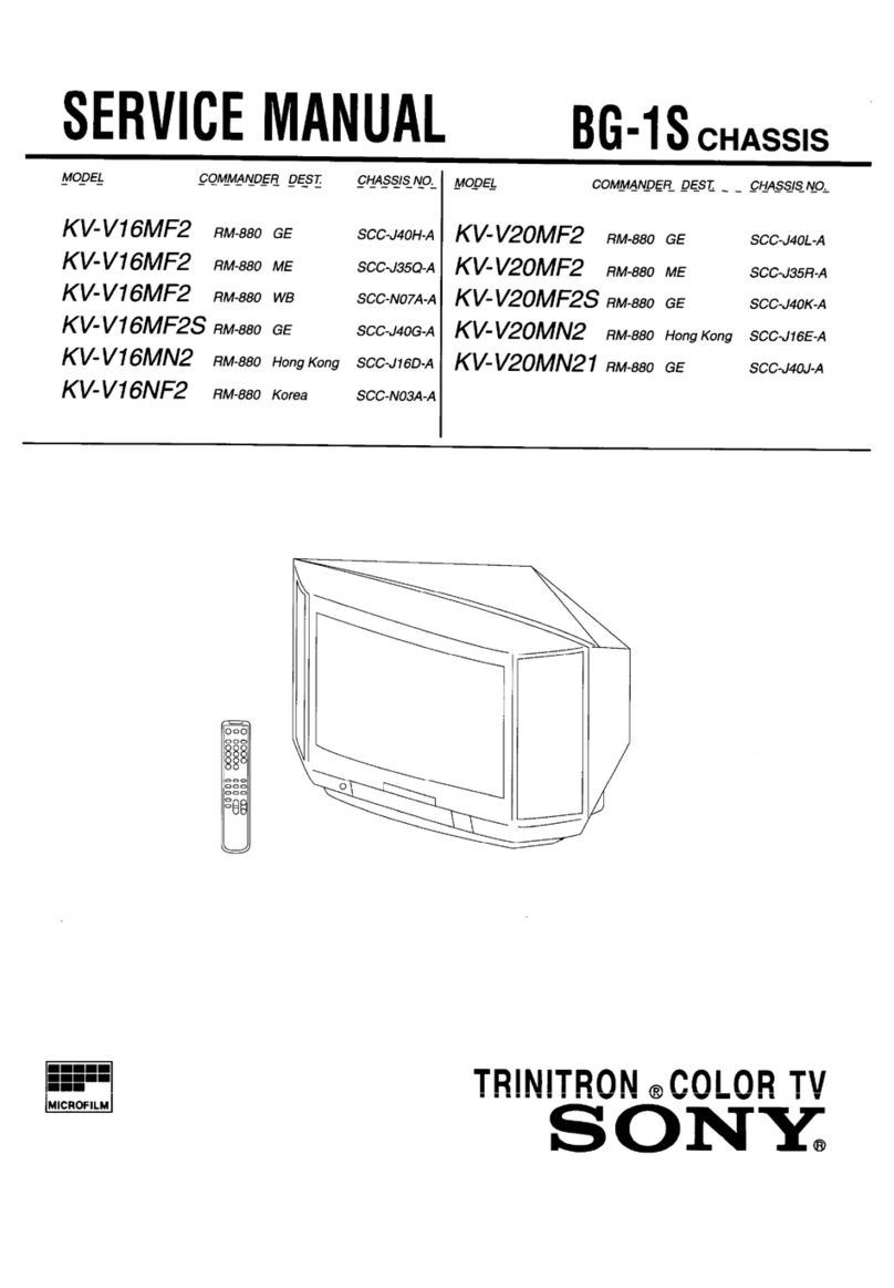
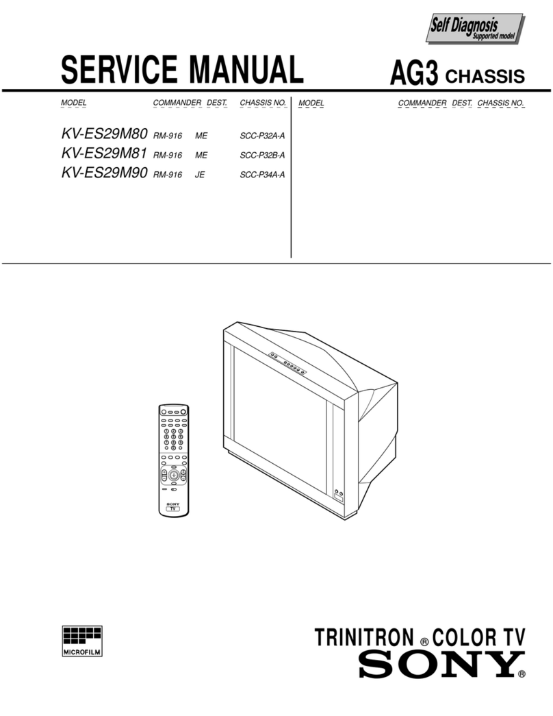
SERVICE
MANUAL
AA-2
cuassis
MODEL
COMMANDER
DEST.
CHASSIS
NO.
|
MODEL
COMMANDER
DEST.
CHASSIS
NO.
KV-27V20
RM-Y135
US
sccu7tH-a
|
KV-29V65M
RM-Y137E
SCC-J7AJ-A
KV-27V20
RM-Y135
Canadian
scc-u73G-4
|
KV-29V75M
RM-Y137E
SCC-U74K-A
KV-27V25
RM-Y137
US
sceuria
|
KV-32V25
RM-Y137
US
SCC-U71L-A
KV-27V25
RM-Y137
Canadian
scc-u73H-A
|
KV-32V25
RM-Y137
Canadian
SCC-J73K-A
KV-27V35
RM-Y137_
US
scou7ik-a
|
KV-32V35
RM-Y137_
US
SCC-U71M-A
KV-27V35
RM-Y137
Canadian
sccv7a/-A
|
KV-32V35
RM-Y137
Canadian
SCC-J73L-A
KV-29V20M
RM-Y135
E
scov7H-a
|
KV-34V35C
RM-Y137_E
SCC-J74M-A
KV-29V35C
—
amyisr
SCC-J74L-A
Note:
1.
Adjustment
Manual
for
this
model
is
separately
published.
Ys
Adjustment
Manual
9-965-822-01
a
—|
KV-27V20/27V25/29V20M
KV-27V35/29V35C/29V75M
29V65M/32V25
32V35/34V35C
SONY.
QTY
WAPC(AS)
HACIA
581601
TRINITRONe
COLOR
TV
SON
Y.
996
29}
[32] [34]
SPECIFICATI
ONS
Television
system
American
TV
standard
Channel
coverage
VHF:
2-13
/
UHF:
14-69
/
CATV:
1-125
Antenna
75-ohm
external
antenna
terminal
for
VHF/UHF
Picture
tube
Hi
Black
Trinitron®
tube
Screen
size
(in.)
27-inch
picture
measured
diagonally
32-inch
picture
measured
diagonally
Power
requirements
120V,
60
Hz
|
120V,60Hz
|
120V,60Hz
|
120V,
60Hz
|
220V,50/60Hz
|
120V,60Hz
|
120V,60Hz
}
120V,
60Hz
|
120V,60Hz
|
200V,50/60Hz
Number
of
inputs/
outputs
Video”
2 3
3 2
3
3
3
3 3
3
S
video”
1
1
2
Audio”
2
3
3
2
3 3
3
3
|
3 3
Audio
out®
1 1
1 1
1
1
1 1 1
1
Monitor
out”
1
1
ae
(Re
a
ees
ee
ee
1
1
TV
out”
=
=
1
a
ee
=
1
=
1
1
s-Link
Se
ee
ee
oy
eee
Speaker
output
(W)
5Wx2
|
5Wx2
|
10Wx2
10W
x2
|
5Wx2
|
10Wx2
|
5Wx2
|
10Wx2
|
10Wx2
Power
consumption
(W)
When
in
use
(Max.)
165W
180W 195W
165W
195W
180W
195W
190W
|
210W,2.75A|
210W
In
standby
ow
13W
OW
13W
9W
13W
9W
13W
13W
Dimensions
(W/H/D)
660.4x
602.5
|
690x5754x
}690x575.4x
|
6604x6025
|
690x5754x
|
690x5754x
|690x5754x
|
821
x
675.3
1821
x
675.3
|
821
x
675.3
(mm)
X521.2mm
|5034mm
=|
503.4
mm
x5212mm
{534mm
=|
534mm
—
|
3503.4mm
x
587mm
{x587mm_
|x587
mm
(in.)
2x
IBYax
|
27x
W/a
VW
YaxWYe
|
2x
BVax
|
74x
IW37a
|
Wax
Wa
[IW
"xI3/e_
|
33"/2x
275/8]33'/2x
27
5/p
|
33
'/2x275/s
20
5/sin.
x197/sin,
|
X197/sin.
20*/sin.
x197/sin.
=
{
x197/sin.
«=f
x197/einn
=|
X24
in.
x24
in.
x
24
in.
Mass
(kg)
40.6
kg
43
kg
43
kg
40.6
kg
43
kg
43
kg
43
kg
70
kg
70
kg
70
kg
(Ibs)
89
Ibs
8
oz
|
94
Ibs
13
oz
|
94
Ibs
13
oz
|
89
Ibs
8.0z
|
94
Ibs
13
oz
|
94
Ibs
13
oz
|
94
Ibs
13
02
|
154
Ibs
6
oz
|
154
Ibs
6
oz
|
154
lbs
6
oz
?
1
Vp-p,
75
ohms
unbalanced,
sync
negative
2
Y:
1
Vp-p,
75
ohms
unbalanced,
sync
negative
C:
0.286
Vp-p
(Burst
signal),
75
ohms
»
500
mVrms
(100%
modulation),
Impedance:
47
kilohms
”
More
than
408
mVrms
at
the
maximum
volume
setting
(variable)
More
than
408
mVrms
(fix)
Impedance:
5
kilohms
Supplied
accessories
Remote
commander
RM-Y135
(1)
(KV-27V20/29V20M
only)
RM-Y137
(1)
(KV-27V25/27V35/29V35C/
29V65M/29V75M/32V25/32V35/
34V35C/35V35/35V45/35V75
only)
Size
AA
(R6)
battery
(2)
Optional
accessories
Connecting
cables
VMC-810S/820S,
VMC-720M,
YC-15V/30V,
RK-74A
TV
Stand
SU-27A
(KV-27V20/27V25/27V35/29V20M/29V35C/
29V65M/29V75M
only)
TV
Stand
SU-32A
(KV-32V25/32V35/34V35C
only)
TV
Stand
SU-35A
(KV-35V35/35V45
only)
U/V
mixer
EAC-66
Design
and
specifications
are
subject
to
change
without
notice.
|
(@)°
SRS
(SOUND
RETRIEVAL
SYSTEM)
The
(@)
SRS
(SOUND
RETRIEVAL
SYSTEM)
is
manufactured
by
Sony
Corporation
under
license
from
SRS
Labs,
Inc.
It
is
covered
by
U.S.
Patent
No.
4,748,669.
Other
US.
and
foreign
patents
pendeing.
The
word
‘SRS’
and
the
SRS
symbol
(@)
are
registered
trademarks
of
SRS
Labs,
Inc.
SAFETY
CHECK-OUT
(US
Model
only)
After
correcting
the
original
service
problem,
perform
the
following
safety
checks
before
releasing
the
set
to
the
customer:
1.
Check
the
area
of
your
repair
for
unsoldered
or
poorly-soldered
connections.
Check
the
entire
board
surface
for
solder
splashes
and
bridges.
2.
Check
the
interboard
wiring
to
ensure
that
no
wires
are
“pinched”
or
contact
high-wattage
resistors.
3.
Check
that
all
control
knobs,
shields,
covers,
ground
straps,
and
mounting
hardware
have
been
replaced.
Be
absolutely
certain
that
you
have
replaced
all
the
insulators.
4.
Look
for
unauthorized
replacement
parts,
par-
ticularly
transistors,
that
were
installed
during
a
previous
repair.
Point
them
out
to
the
cus-
tomer
and
recommend
their
replacement.
5.
Look
for
parts
which,
though
functioning,
show
obvious
signs
of
deterioration.
Point
them
out
to
the
customer
and
recommend
their
replace-
ment.
6.
Check
the
line
cords
for
cracks
and
abrasion.
Recommend
the
replacement
of
any
such
line
cord
to
the
customer.
7.
Check
the
B+
and
HV
to
see
if
they
are
at
the
values
specified.
Make
sure
your
instruments
are
accurate;
be
suspicious
of
your
HV
meter
if
sets
always
have
low
HV.
8.
Check
the
metal
trim,
metallized
knobs,
screws,
and
all
other
exposed
metal
parts
for
AC
leakage.
Check
leakage
as
described
below.
To
Exposed
Metal
Parts
on
Set
AC
==
voltmeter
(0.75V)
=
Earth
Ground
Fig.
A.
Using
an
AC
voltmeter
to
check
AC
leakage.
LEAKAGE
TEST
The
AC
leakage
from
any
exposed
metal
part
to
earth
ground
and
from
all
exposed
metal
parts
to
any
exposed
metal
part
having
a
return
to
chassis,
must
not
exceed
0.5mA
(500
microampers).
Leakage
current
can
be
measured
by
any
one
of
three
methods.
1.
A
commercial
leakage
tester,
such
as
the
Simpson
229
or
RCA
WT-540A.
Follow
the
manufactures’
instructions
to
use
these
instru-
ments.
2.
A
battery-operated
AC
milliammeter.
The
Data
Precision
245
digital
multimeter
is
suitable
for
this
job.
3.
Measuring
the
voltage
drop
across
a
resistor
by
means
of
a
VOM
or
battery-operated
AC
volt-
meter.
The
“limit”
indication
is
0.75V,
so
analog
meters
must
have
an
accurate
low-
voltage
scale.
The
Simpson
250
and
Sanwa
SH-63Trd
are
examples
of
a
passive
VOM
that
is
suitable.
Nearly
all
battery
operated
digital
multimeters
that
have
a
2V
AC
range
are
suitable.
(See
Fig.
A)
HOW
TO
FIND
A
GOOD
EARTH
GROUND
A
cold-water
pipe
is
guaranteed
earth
ground;
the
cover-plate
retaining
screw
on
most
AC
outlet
boxes
is
also
at
earth
ground.
If
the
retaining
screw
is
to
be
used
as
your
earth-ground,
verify
that
it
is
at
ground
by
measuring
the
resistance
between
it
and
a
cold-
water
pipe
with
an
ohmmeter.
The
reading
should
be
zero
ohms.
If
a
cold-water
pipe
is
not
accessible,
connect
a
60-100
watts
trouble
light
(not
a
neon
lamp)
between
the
hot
side
of
the
receptacle
and
the
retaining
screw.
Try
both
slots,
if
necessary,
to
locate
the
hot
side
of
the
line,
the
lamp
should
light
at
normal
brilliance
if
the
screw
is
at
ground
potential.
(See
Fig.
B)
rouble
Light
AC
Outlet
Box
Ohmmeter
a
|
Fig.
B.
Checking
for
earth
ground.
i)
Cold-water
Pipe
TABLE
OF
CONTENTS
(CAUTION)
SHORT
CIRCUIT
THE
ANODE
OF
THE
PICTURE
TUBE
AND
THE
ANODE
CAP
TO
THE
METAL
CHASSIS,
CRT
SHIELD,
OR
CARBON
PAINTED
ON
THE
CRT,
AFTER
REMOVING
THE
ANODE.
WARNING!!
AN
ISOLATION
TRANSFORMER
SHOULD
BE
USED
DURING
ANY
SERVICE
TO
AVOID
POSSIBLE
SHOCK
HAZARD,
BECAUSE
OF
LIVE
CHASSIS.
THE
CHASSIS
OF
THIS
RECEIVER
IS
DIRECTLY
CONNECTED
TO
THE
AC
POWER
LINE.
SAFETY-RELATED
COMPONENT
WARNING!!
COMPONENTS
IDENTIFIED
BY
SHADING
AND
MARK
A
ON
THE
SCHEMATIC
DIAGRAMS,
EXPLODED
VIEWS
AND
IN
THE
PARTS
LIST
ARE
CRITICAL
FOR
SAFE
OPERATION.
REPLACE
THESE
COMPONENTS
WITH
SONY
PARTS
WHOSE
PART
NUMBERS
APPEAR
AS
SHOWN
IN
THIS
MANUAL
OR
IN
SUPPLEMENTS
PUBLISHED
BY
SONY.
CIRCUIT
ADJUSTMENTS
THAT
ARE
CRITICAL
FOR
SAFE
OPERATION
ARE
IDENTIFIED
IN
THIS
MANUAL.
FOLLOW
THESE
PROCEDURES
WHENEVER
CRITICAL
COMPONENTS
ARE
REPLACED
OR
IMPROPER
OPERATION
IS
SUSPECTED.
Section
Title
Page
Section
Title
Page
1.
GENERAL
2.
DISASSEMBLY
WelCOmMe
lia...
ccsicscsisececsoesscscesescsencopudecasvesdcccovesesssnssds
cossoangters
5
2-1.
Rear
Cover
Removal
......cccssscssssssecestesessersessssees
22
Checking
your
model
number
........cccssccscccssnsseesesseseesresenees
5
2-2.
Chassis
Assy
Removal
.......cccsccccssessecsstscscesetensesvase
22
Step
1S
HOOKUD
sas
cavisssaseesecssaias
cecvensosseveevstescvasuceasedvoesacaesey
ste
5
2-3.
Service
POSitiON
.......ccsscccccssssesesseessstesesessenecesseneee
22
Step
2:
Installing
the
glass
door
and
adjusting
the
shelf
........
9
2-4.
Control
Switch
Removal
Step
3:
Setting
up
the
remote
commander
........seeseeseees
10
(KV-27V35/29V35C/29V75M/32V35/34V35C)
...
22
Step
4:
Setting
up
the
TV
automatically
(AUTO
SET
UP)...
10
2-5.
Picture
Tube
Removal
(KV-27V20/27V25/
Changing
the
menu
language
.........cssssccscesseseseeseseeecssees
12
27V35/29V20M/29V35C/29
V65M/29V75M)
.......
23
Adjusting
the
tilt
of
the
picture
(TILT
CORRECTION)
.......
12
2-6.
Picture
Tube
Removal
Watching
the
TV
.u....cscssssesseseseseeesees
12
(KV-32V25/32V35/34V35C)
uo.
sesssscsssereseeesterteeeesses
23
Watching
two
programs
at
a
time-PIP
13
Adjusting
the
picture
(VIDEO)
sssssssseooone
14
3.
SAFETY
RELATED
ADJUSTMENTS
..................
25
Selecting
the
video
mode
(VIDEO)
.....sssssssessssesessssseessseesssees
14
4.
DIAGRAMS
Adjusting
picture
brightness
automatically
4-1.
Block
Diagrams
0...
ccsessesssssceescssessssscasssseeses
(LIGHTSENSOR)
...ccccsssssssssssssosvsscsesssssscessenesssosvavescesessenes
15
4-2.
Circuit
Boards
Location
Adjusting
the
sound
(AUDIO)
15
4-3.
Printed
Wiring
Boards
and
Schematic
Diagrams....
35
Using
audio
effect
(EFFECT)
15
@
PSBOard
or
casscatsteestendicddvecadeencensnsessencetsrdesgacansseessooonts
36
Selecting
stereo
or
bilingual
programs
(MTS)
...........scseee
16
©
SC
Board
visissccisscnssccsdsasisecisisasstaivassecsssaxanceeasstennsees
39
Setting
the
speaker
switch
(SPEAKER)
........sscsccsssssessesens
16
WA
Board
visscesccsissceteccensecesans
oassacssiecsnarsseesvaesseguaeevees
41
Setting
audio
out
(AUDIO
OUT)
.......cseeesessocesseseesteeeees
16
OU
Boat
iicccisseiecssiteveesincnvscecarssadsveorsdcsveiecsesivaasies
47
Setting
daylight
saving
time
(DAYLIGHT
SAVING)..........
17
©
WB,
SC
Boards
.......ccccccssssscecsssescssesseessscencatsseeeees
52
Setting
the
clock
(CURRENT
TIME
SET).......ccssscssssssseees
17
HV,
HS
Boards
.....ccccsesesseccsssssescsssecersscsecreecssens
55
Setting
the
timer
to
turn
the
TV
on
and
off
©
C,
G
Boards
itis
cccssscisseccissovssssosicssecieasesiscatasensaicesect
59
(ON/OFF
TIMER)
...ccssssssssscsssessssssnecsssesescsssessesssnessseeesoees
17
CAV,
KK
Board
ci
feciectssssaccestedasesvsssesvstnitedesersssesrasecess
64
Customizing
the
channel
names
(CHANNEL
CAPTION)...
18
4-4,
SeMiCONAUCTOLS
......sccccsssccrceresrcerssrcesessseeeeseeeecsaseecens
70
Blocking
out
a
channel
(CHANNEL
BLOCK)
..........sscss00
18
Setng
your
favorite
channels
(FAVORITE
CHANNEL)...
18>
oa
pips
KV-32V25/32V35/34V35C)
....
71
Setting
video
labels
(VIDEO
LABEL)
.........c.sssessscesssessesees
5-2,
Picture
Tube
>
Penne
a
vale
Caley
™ey)
(EXCEPT
KV-32V25/32V35/34V35C)
sacsssceesseee
2B
Saale
BE
NES
OE
aR
5-3.
Chassis
(KV-32V25/32V35/34V35C)
sasesssannse
14
;
a
5-4.
Picture
Tube
(KV-32V25/32V35/34V35C)
«0...
75
Troubleshooting
........csscssssssssessevsesssersessessesssssssssssesnsesssesesess
6.
ELECTRICAL
PARTS
LIST...
cesses
76
(ATTENTION)
APRES
AVOIR
DECONNECTE
LE
CAP
DE
L'ANODE,
COURT-
CIRCUITER
L'ANODE
DU
TUBE
CATHODIQUE
ET
CELUI
DE
L'ANODE
DU
CAP
AU
CHASSIS
METALLIQUE
DE
L'APPAREIL,
OU
AU
COUCHE
DE
CARBONE
PEINTE
SUR
LE
TUBE
CATHODIQUE
OU
AU
BLINDAGE
DU
TUBE
CATHODIQUE.
ATTENTION!!
AFIN
D'EVITER
TOUT
RESQUE
D'ELECTROCUTION
PROVENANT
D'UN
CHASSIS
SOUS
TENSION,
UN
TRANSFORMATEUR
D'ISOLEMENT
DOIT
ETRE
UTILISE
LORS
DE
TOUT
DEPANNAGE.
LE
CHASSIS
DE CE
RECEPTEUR
EST
DIRECTEMENT
RACCORDE
A
L'ALIMENTATION
SECTEUR.
ATTENTION
AUX
COMPOSANTS
RELATIFS
A
LA
SECURITE!!
LES
COMPOSANTS
IDENTIFIES
PAR
UNE
TRAME
ET
PAR
UNE
MARQUE
A
SUR
LES
SCHEMAS
DE
PRINCIPE,
LES
VUES
EXPLOSEES
ET
LES
LISTES
DE
PIECES
SONT
D'UNE
IMPORTANCE
CRITIQUE
POUR
LA
SECURITE
DU
FONCTIONNEMENT.
NE
LES
REMPLACER
QUE
PAR
DES
COMPOSANTS
SONY
DONT
LE
NUMERO
DE
PIECE
EST
INDIQUE
DANS
LE
PRESENT
MANUEL
OU
DANS
DES
SUPPLEMENTS
PUBLIES
PAR
SONY.
LES
REGLAGES
DE
CIRCUIT
DONT
L'IMPORTANCE
EST
CRITIQUE
POUR
LA
SECURITE
DU
FONCTIONNEMENT
SONT
IDENTIFIES
DANS
LE
PRESENT
MANUEL.
SUIVRE
CES
PROCEDURES
LORS
DE
CHAQUE
REMPLACEMENT
DE
COMPOSANTS
CRITIQUES,
OU
LORSQU'UN
MAUVAIS
FONCTIONNEMENT
EST
SUSPECTE.
Thank
you
for
purchasing
the
Sony
Trinitron®
Color
TV.
Here
are
some
of
the
features
you
will
enjoy
with
your
TV:
¢
On-screen
menus
that
let
you
set
the
picture
quality,
sound,
and
other
settings.
*
Picture-in-Picture
(PIP)
that
allows
you
to
watch
another
TV
channel,
video
or
cable
image
as
a
window
picture.
*
Surround
system
that
simulates
the
sound
quality
of
a
concert
hall
or
movie
theater
(KV-27525/27535/
29RS25/29RS25C/32$25/32535/32T
W25
only).
*
SRS
(SOUND
RETRIEVAL
SYSTEM)
that
allows
you
to
receive
realistic
sound
that
recaptures
audio
“clues”
originally
present
but
masked
in
the
recording
process
so
that
the
action
seems
to
happen
all
around
you
(KV-27V25/27V35/29V35C/
29V65M/29V75M/32V25/32V35/34V35C/35V35/
35V45/35V75
only).
*
LightSensor™
that
automatically
adjusts
the
brightness
of
the
picture
(KV-27V25/27V35/29V35C/
29V65M/29V75M/32V25/32V35/34V35C/35V35/
35V45/35V75
only).
«
S-Link™
that
allows
you
to
automatically
change
the
TV’s
input
mode,
turn
on
the
VCR,
and
play
a
tape
by
just
pressing
the
VCR's
play
button
(KV-27V25/27V35/29
V35C/29
V65M/29V75M/32V25/
32V35/34
V35C/35V35/35V45/35V75
only).
This
feature
is
originally
designed
by
Sony.
SECTION
1
GENERAL
Checking
your
raxeye(-)Malelarlel-te
The
instructions
in
this
manual
are
for
the
eighteen
models
listed
below.
Before
you
start
reading,
check
your
model
number
by
looking
at
the
rear
of
your
TV.
The
KV-27825
is
the
model
used
for
illustration
purposes.
Any
differences
in
operation
are
clearly
indicated
in
the
text,
for
example,
“KV-27525
only.”
Instructions
in
this
manual
are
based
on
the
remote
commander.
You
can
also
use
the
controls
on
the
TV
if
they
have
the
same
name
as
those
on
the
remote
commander.
Feature
packages
N
fs
s/2/#8/
8
s/s
/
Be/
#
ef
§
/
§
/
s8/
§
Model
#
é
gS
J
5
Pod
number
&
é
a
be
Po
KV-27V20
°
]
KV-27835
.
KV-27V25
.
|
°
KV-27V35
.
.
Kv-29v20_
|
KV-29RS25C
.
KV-29V35C__
|
°
.
KV-29V65M
.
.
KV-29V75M
° .
KV-32525
.
HE
|
KV-32535
.
KV-32TW25
°
KV-32V25
. .
KV-32V35_|
’ :
KV-34V35C
-
fe
KV-35V35
.
.
°
KV-35V45_
Lie
;
KV-35V75
i
. ° °
Step
1:
Hookup
Although
you
can use
either
an
indoor
or
outdoor
antenna
with
your
TV,
we
recommend
that
you
connect
an
outdoor
antenna
or
a
cable
TV
system
to
get
better
picture
quality.
How
to
connect
different
types
of
cables
The
illustrations
below
show
examples
of
connecting
cables
to
the
TV
directly.
A
(Rear
of
TV)
¢
VHF
only
75-ohm
coaxial
cable
VHF/UHF
or
)
pref)
¢
VHF/UHF
or
*
Cable
B
(Rear
of
TV)
¢
VHF
only
—300-ohm
twin
lead
cable
or
©
UHF
only
or
©
VHF/UHF
Antenna
connector
VHF/UHF
Cc
75-ohm
coaxial
cable
«
VHF
y
py
{Rear
of
TV)
VHF/UHF
and
}]
EAC-66
U/V
mixer
t
|
(not
supplied)
e
Ube
300-ohm
twin
lead
cable
Notes
*
Most
VHF/UHF
combination
antennas
have
a
signal
splitter
Remove
the
splitter
before
attaching
the
appropriate
connector.
*
If
you
use
the
U/V
mixer,
snow
and
noise
may
appear
in
the
picture
when
viewing
cable
TV
channels
over
37.
The
operating
instruction
mentioned
here
are
partial
abstracts
from
the
Operating
Instruction
Manual.
The
page
numbers
of
the
Operating
Instruction
Manual
remain
as
in
the
manual.
(Part
no:
3-810-687-22)
Connecting
an
antenna/cable
TV
system
without
a
VCR
If
your
cable
company
requires
you
to
connect
a
cable
box,
make
the
connection
as
follows:
Cable
or
antenna
(Rear
of
TV)
Cable
VHF/UHF
——
=D
—*P
Cable
box
(Rear
of
TV)
VHF/UHF
Cable
3
D
IN
OUT
Cable
box
Cable
box
and
cable
@
KV-27835/27V35/29V35CI29V75MI32S35/32V35!
34V35CI35V35/35V45/35V75
only
(Rear
of
TV)
AUX
TO
CONVERTER
75-ohm
coaxial
cable
(not
supplied)
Cable
box
VHF/UHF
CATV
cable
5
oH)
Pay
cable
TV
systems
use
scrambled
or
encoded
signals
requiring
a
cable
box*
in
addition
to
the
normal
cable
connection.
*
The
cable
box
will
be
supplied
by
the
cable
company
Note
*
You
cannot
watch
the
signal
through
AUX
connector
as
a
window
picture.
Cable
and
antenna
W
KV-27S35/27V35/29V35CI2Z9V7SMIZ2S835/132V35!
34V35C/3SV35/35V45/35V75
only
(Rear
of
TV)
AUX
CATV
cable
3
D
TO
CONVERTER
VHF/UHF
Antenna
cable
;
Note
*
Do
not
connect
anything
to
the
TO
CONVERTER
connector
in
this
case.
Getting
Started
5
Coane
ee
see
aera
er
see
sees
see
ee
ee
ee
TE
eee
ee
EE
Connecting
an
antenna/cable
TV
system
with
a
VCR
To
connect
your
VCR
to
the
TV,
first
check
the
model
number
of
your
TV
and
select
the
corresponding
connection.
For
details
on
connection,
see
the
instruction
manual
of
your
VCR.
Before
making
the
connection,
disconnect
the
AC
power
cords
of
the
equipment
to
be
connected.
After
making
these
connections,
you
will
be
able
to
do
the
following:
In
order
to
operate
PIP,
a
VCR
must
be
connected
to
*
View
the
playback
of
video
tapes
your
TV
and
turned
on
(KV-27525/27V25/29RS25/
¢
Record
one
TV
program
while
viewing
another
29RS25C/29V65M/32S25/32TW25/32V25
only).
program
¢
Watch
two
TV
programs
at
once
using
PIP
Without
a
cable
box
{Rear
of
TV)
VIDEO
IN
S$
VIDEO
VHF/UHF
AUDIO
OUT
Antenna
cable
WARFIX)
=£i-46)
vcR
Cable
VIDEO
(yellow)
AUDIO-L
(white)
AUDIO-R
(red)
VMC-810S/820S
(not
supplied)
Note
*
To
connect
a
monaural
VCR,
connect
the
audio
output
of
the
VCR
to
AUDIO-L
(mono)
of
VIDEO
1
IN
on
the
TV
To
an
S
video
equipped
VCR
without
a
cable
box
If
your
VCR
has
an
S
video
output
jack,
make
the
following
connections.
(Rear
of
TV)
(VIDEO
IN)
2]
S
VIDEO
'
‘
VHF
UKF
Antenna
cable
VHF/UHE
O)
VCR
‘AUDIO
OUT
(aR
FX)
Cable
$
VIDEO
AUDIO-R
(red)
AUDIO-L
(white)
YC-15V/30V
{not
supplied)
RK-74A
(not
supplied)
6
Getting
Started
With
a
cable
box
Note
Antenna
cable
(Rear
of
TV)
VHF/UHF
VHF/UHF
Cabie
box
*
To
connect
a
monaural
VCR,
connect
the
audio
output
of
the
VCR
to
AUDIO-L
(mono)
of
VIDEO
1
IN
on
the
TV.
To
an
S
video
equipped
VCR
with
a
cable
box
Antenna
cable
VIDEO
IN
AUDIO
OUT
{VARIO
©re
©t
J
VHFAUHF
VHF/UHF
Cable
a
==]
—i
|
<
Splitter
Note
bo
Cable
box
*
Video
signals
are
composed
ot
Y
(luminance)
and
C
(chroma)
signals.
The
S
connection
sends
the
two
signals
separately
preventing
degradation,
and
gives
better
picture
quality
compared
to
conventional
connections.
VMC-810S/820S
{not
supplied)
=~)
AUDIO-R
(red)
AUDIO-L
(white)
VIDEO
(yellow)
(Rear
of
TV)
VIDEO
IN
jAUDIO
OUT
(WAR
FIX)
5)
ee
are
|
Or
|
@r
Y¥C-15V/30V
RK-74A
(not
supplied)
(not
supplied)
S
VIDEO
AUDIO-R
(red)
AUDIO-L
(white)
Getting
Started
7
SSS
A
a
2
Connecting
a
DBS
receiver
For
connection
details,
see
the
instruction
manual
of
the
DBS
(Digital
Broadcasting
Satellites)
receiver.
ToaTv
(Rear
of
TV)
Cable
or
cable
box
VIOEO
IN
4
VHF/UHE
|
YREUHF
DBS
receiver
Antenna
VHF/UHF
Satelline
auoio_viogco
_svioeco
|@]
in
antenna
©
OUT
input
VIDEO
(yellow)
AUDIO-L
(white)
AUDIO-R
(red)
VMC-810S/8205S
(not
supplied)
Note
*
You
can use
the
$
VIDEO
jack
or
the
composite
video
jack
tor
the
video
connection.
To
a
TV
and
VCR
Cable
or
cable
box
DBS
receiver
Antenna
VHFIUHF
Tl
-
aupio
wideo
_svineo
|G)
Satellite
antenna
@
©
(9)
input
{Rear
of
TV)
VIDEO
IN
i
:
J
-L-
——
|__|
z,
G
VHF/UHF
+O)
woe
pails
F-type
cable
UHF
OUT
(not
supplied)
VHF/UHF
IN
VHF/UHF
4
3
2
VIDEO
(yellow)
AUDIO-L
(white)
AUDIO-R
(red)
VMC-810S/820S
(not
supplied)
8
Getting
Started
Connecting
a
camcorder
WW
KV-27V25/27V35/29V35CI29VESMI2Z9V7SM/3Z2V251
32V35/34V35CI35V35/35V45/35V75
only
This
connection
is
convenient
for
viewing
a
camcorder
picture.
(Front
of
KV-27V2S/27V35/29V35C/
29V65M/29V75M/32V25/35V35)
(Front
of
KV-32V35/34V35C/35V45/35V75)
YEO
PUT
VIDEO
LWOMOAUOO-R
AUDIO-R
(red)
AUDIO-L
(white)
AUDIO-R
VIDEO
(red)
(yellow)
AUDIO-L
(white)
(yellow)
Video
and
audio
outputs
VMC-810S/820S
(not
supplied)
Note
*
To
connect
a
monaural
camcorder,
connect
the
audio
output
of
the
camcorder
to
AUDIO-L
(mono)
of
VIDEO
2
INPUT
on
the
Tv.
Connecting
an
audio
system
When
connecting
audio
equipment,
see
page
27
for
more
information.
(Rear
of
TV)
VIDEO
IN
1
=o)
bisa
|
Aupio
out
RK-74A
(not
supplied)
Set
the
amplifier’s
©
\noeo
(VAR
FIX)
function
to
line
input.
(..
RY
|
AUDIO
OUT-L
(white)
¢
nor)
Q
:
UY
AUDIO
OUT-R
(red)
Getting
Started
9
Connecting
two
VCRs
for
tape
editing
using
MONITOR
OUT
@
KV-27V25/27V35129V35CI29VESMI2Z9V75MI3Z2V25/
32V35/34V35CI35V35/35V45/35V75
only
MONITOR
OUT
allows
you
to
record
a
program
that
is
on
the
screen.
VCR
(for
playback)
AUDIO
VIDEO
(Rear
of
TV)
VCR
(for
recording)
AUDIO-R
(red)
AUDIO-L
(white)
VIDEO
(yellow)
VMC-810S/820S
(not
supplied)
The
above
type
of
connection
should
only
be
used
°
when
you
connect
from
the
line
input
of
one
VCR,
and
from
the
line
output
of
a
second
VCR.
Notes
*
Do
not
change
the
input
signal
while
editing
through
MONITOR
OUT,
or
the
output
signal
will
also
change
©
You
can
use
the
§
video
jack
to
connect
a
VCR
tor
playback
and
the
composite
video
jack
to
connect
a
VCR
for
recording,
VMC-810S/820S
(not
supplied)
When
connecting
a
single
VCR
to
the
TV,
do
not
connect
the
MONITOR
OUT
jacks
at
the
rear
of
the
TV
to
the
VCR's
line
input,
while
at
the
same
time
connecting
from
the
TV’s
VIDEO
IN
jacks
to
the
VCR's
line
output,
as
shown
below
{Rear
of
TV)
Using
the
S-Link
function
@
KV-27V25/27V35/29V35CI29VESMI2Z9V75MI3Z2V25!1
.
32V35/Z4V35CIZ5V35/35V45135V75
only
The
S-Link
feature
allows
you
to
operate
the
TV
and
VCR
with
the
$-Link
function
in
the
following
ways:
¢
When
you
press
the
VCR’s
play
button,
the
TV’s
input
mode
is
automatically
changed
to
video,
and
the
VCR
starts
playing
a
tape.
VCR
AUDIO
VIDEO
{INE
IN
{©
© ©
Sunk
ue
ot
|
@
@
|
Q}
VIDEO
(yellow)
AUDIO-L
(white)
AUDIO-R
(red)
Audio/video
cable
Getting
Started
tnovsupplied)
10
S-LINK
OUT
You
can
turn
oft
the
TV
and
VCR
together
using
the
SYSTEM
OFF
button
(see
page
35
for
details).
Notes
«
The
TV
may
malfunction
if
vou
connect
the
S-Link
cable
to
the
TV
without
connecting
the
other
end
of
the
cable
to
the
VCR
¢
When
making
the
S-Link
connection,
be
sure
to
insert
all
the
connectors
firmly
(Rear
of
TV}
a
01
woeo3!
a
SEO
__ouT
_}
'GONTOR
A000
oo
ee
—vngo-—--<O)}
wis
+O|O'
50}
—--—-olo)
prem
er
|
———
Connecting
an
AV
receiver
Connect
an
optional
AV
receiver
to
the
VIDEO
1
IN
jacks
at
the
rear
of
the
TV.
VMC-810S/8205
(not
supplied)
VIDEO
(yellow)
AUDIO-L
(white)
AUDIO-R
(red)
(Rear
of
KV-27V35)
Monitor
E
H
Monitor
audio
TV
audio
input
AUDIO-R
(red)
AUDIO-L
(white)
VIDEO
(yellow)
VMC-810S/820S
(not
supplied)*
*
(KV-27V35/29V35C/29V75M/32V35/34V35C/35V45/
35V75
only)
Make
this
connection
if
your
TV
has
the
TV
OUT
jacks.
When
you
connect
an
AV
receiver
to
the
TV
using
the
AV
receiver's
TV
input
jacks,
it
is
recommended
to
set
VIDEO
1
IN’s
video
label
to
“RECEIVER”
(see
page
32
for
details).
Getting
Started|
11
Step
2:
Installing
dats)
Installing
the
glass
door
Adjusting
the
shelf
i
re
|
re
1
check
that
the
projection
of
the
screw
1
Unlock
the
four
shelf
supports
with
a
g
ass
roy]
g
r=
|
9]
through
the
hinge
allows
for
proper
medium
Philips
head
screwdriver.
Turn
the
installation
of
the
hinge
to
the
glass
door,
screwdriver
90°
to
unlock
the
shelf
adjusting
the
shelf
and
then
insert
the
bottom
hinge
@
into
supports.
the
hole
located
at
the
bottom,
right
side
of
cabinet.
@
KV-32TW25/35V75
only
Follow
these
instructions
to
install
the
glass
door
and
adjust
the
shelf.
2
Gently
slide
the
shelf
up
and
out.
Check
projection
of
this
area
of
screw
3)
2
Attach
the
top
hinge
@
to
the
right
side
of
the
glass
door,
tighten
the
screws
snugly,
but
do
not
overtighten.
Attach
the
plate
pad
@
to
the
left
side
and
push
the
plate
@
over
the
plate
pad.
3
insert
shelf
supports
in
the
appropriate
holes.
Slide
shelf
in,
align
the
shelf
grooves
with
the
shelf
supports,
and
slide
the
shelf
down.
Push
here
to
close.
To
open,
push
again,
Parts
List
@
Bottom
hinge
1
5
3
Push
the
top,
glass
door
hinge
into
the
top,
@
Tophinge
Qe a)
1
right
bushing
and
gently
slide
the
glass
door
into
the
bottom
hinge.
Adjust
the
©
Screw4x4
Om
4
glass
door
until
level,
and
tighten
the
hinge
screws.
©
Plate
pad
ee
1
@
Plate
1
Note
*
The
glass
door
is
made
ot
tempered
glass.
Although
it
is
more
shock-resistant
than
ordinary
glass,
tempered
glass
may
ing
Started
shatter
if
it
is
dropped
or
receives
a
sudden
shock.
Getting
13
12
|
Getting
Started
Yt)
eC
het
-iddiare
mele
the
remote
commander
Inserting
batteries
Insert
two
size
AA
(R6)
batteries
(supplied)
by
matching
the
+
and
-
on
the
battery
to
the
diagram
inside
the
battery
compartment.
Notes
*
Under
normal!
conditions,
batteries
will
last
up
to
six
months.
If
the
remote
commander
does
not
operate
properly
or
the
indicators
of
the
buttons
on
the
remote
commander
do
not
light
up,
the
batteries
may
be
worn
out.
When
replacing
batteries,
replace
both
of
them
with
new
ones.
¢
Do
not
mix
old
batteries
with
new
ones
or
mix
different
types
of
batteries
together.
If
the
electrolyte
inside
the
battery
should
leak,
wipe
the
contaminated
area
of
the
battery
compartment
with
a
cloth
and
replace
the
old
batteries
with
new
ones.
To
prevent
the
electrolyte
from
leaking,
remove
the
batteries
when
you
don't
plan
to
use
the
remote
commander
for
a
long
period
of
time.
*
Do
not
handle
the
remote
commander
roughly.
Do
not
drop
it,
step
on
it
or
let
it
get
wet.
*
Do
not
place
the
remote
commander
in
direct
sunlight,
near
a
heater,
or
where
the
humidity
is
high.
14
|
Getting
Started
Getting
to
know
buttons
on
the
remote
commander
Names
of
buttons
on
the
remote
commander
are
indicated
in
different
colors
to
represent
the
available
functions.
Button
color
Transparent
.......
TV/VCR/DBS/Cable
box
function
(light
up)
buttons.
Press
the
appropriate
function
button
first
to
change
the
remote
commander’s
function.
GIeN
oo
sesseeeeseees
Buttons
relevant
to
power
operations.
Label
color
White
ou...
TV/VCR/DBS/Cable
box
operation
buttons.
.
PIP
operation
buttons.
.
DBS
operation
buttons.
Step
4:
Setting
up
the
TV
automatically
(AUTO
SET
UP)
You
can
set
up
your
TV
easily
by
using
the
AUTO
SET
UP
feature.
It
presets
all
the
receivable
channels.
To
set
up
the
TV
manually,
see
“Setting
cable
TV
on
or
off”
(page
17)
and
“Presetting
channels”
(page
17).
(Front
of
TV)
SETUP
TVVIDEO
=
VOLUME-
=
CHANNEL»
—
POWER,
ie
EO
sone
=
~
4
PIP
For
KV-27V35/29V35C
/29V75M/32V35/34V35C
/
35V45/35V75,
the
control
buttons
are
located
on
the
top
of
the
TV.
Before
you
start
using
AUTO
SET
UP,
be
sure
to
connect
the
antenna
or
cable
to
the
TV
(see
page
5).
1.
Press
POWER
to
turn
on
the
TV.
The
AUTO
SET
UP
screen
appears.
POWER
ENGLISH
ICH
|
ESPANOL
CH-]
AUTOSETUP
—
[VOL-|
DEMO.
[tv
woEol
Fust
please
connect
‘he
antenna
Press
{SET
UP]
to
ext
Note
¢
The
AUTO
SET
UP
screen
appears
whenever
you
press
the
POWER
button
if
vou
do
nat
execute
AUTO
PROGRAM
2
(Except
Canadian
models)
Press
CHANNEL
+
to
select
English
screens
or
CHANNEL
-
to
select
Spanish
screens.
—
CHANNEL
+
3
Press
VOLUME
-.
—
VOLUME
+
AUTO
PROGRAM
“AUTO
PROGRAM”
appears
on
the
screen
and
the
TV
starts
scanning
and
presetting
channels
automatically.
When
all
the
receivable
channels
are
stored,
“AUTO
PROGRAM”
disappears
and
the
lowest
numbered
channel
is
displayed.
If
the
TV
receives
cable
TV
channels,
CABLE
is
set
to
ON
automatically.
To
perform
AUTO
SET
UP
again
1
Press
SET
UP
on
the
TV.
2
(Except
Canadian
models)
Press
CHANNEL
+
or
CHANNEL
-
to
select
the
language.
3
Press
VOLUME
-.
The
picture
and
sound
settings
will
be
set
to
the
factory
preset
conditions.
4
Press
CHANNEL
+.
“AUTO
PROGRAM"
appears
on
the
screen
and
the
TV
starts
scanning
and
presetting
channels.
5
Press
CHANNEL
=
to
exit
the
AUTO
SET
UP
menu.
To
exit
AUTO
PROGRAM
Press
any
button
Notes
*
[f
the
TV
is
set
toa
video
input,
you
cannot
execute
AUTO
SET
UP.
Press
TV
(black
button)
so
that
a
channel
number
appears
Using
the
AUX
connector,
press
TV
(black
button)
first
and
make
sure
that
“AUX"
is
displaved
beside
the
channel
number
on
the
screen
Then
follow
the
procedure
above
to
perform
AUTO
SET
UP
(KV-27535/27V'35/29V35C/29
V73M/32535/
32V35/34\'35C
35V35/35V45/35V75
only)
To
browse
the
main
functions
(DEMO)
Press
TV/VIDEO
on
the
TV
in
step
3.
The
functions
and
menus
are
displayed
one
by
one.
To
exit
DEMO
Press
any
button
Getting
Started|
15
a
Erasing
or
adding
channels
After
AUTO
SET
UP,
you
can
erase
unnecessary
channels
or
add
the
channels
you
want.
Preset
channels
during
the
day
rather
than
late
at
night,
when
some
channels
may
not
be
broadcasting.
TV
(FUNCTION)
0-9
buttons
ENTER
1
Press
TV
(FUNCTION).
-+-
FUNCTION
—
TV
2
Press
MENU.
The
main
menu
appears.
OBE
STANOARO
A
MENU
3
|
PICTURE
17)
HUE
a}
EoLoR.
BRIGHTNESS
See
ao
SHABENESS
—
MENU
Use
Ua
&)
Ext
Ga
3
Press
4
or
¢
to
select
&,
and
press
(>.
The
SET
UP
menu
appears.
SEY
UP.
mDCHANNEL
ERASE/ADD
CHANNEL
CAPTION
GHANNEL
BLOCK
FAVORITE
CHANNEL
CABLE
ON
16
|
Getting
Started
4
Press
¢
or
#
to
select
CHANNEL
ERASE/ADD,
and
press
@.
The
CHANNEL
ERASE/ADD
menu
appears.
CHANNEL
ERASE/ADD.
vERASE
‘ADD
MENU
3
Useio
-
9}or
(CH-/-]
10
Select
the
channel
Use
HD
@
Ext
5
erase
and/or
add
channels:
To
erase
an
unwanted
channel
(1)
Make
sure
the
cursor
()
is
beside
ERASE.
(2)
Press
CH
+/-
or
the
0
-
9
buttons
to
select
the
channel
you
want
to
erase,
and
press
ENTER.
Selected
channel
number
‘CHANNEL
ERASE,ADD:
a
PERASE
ADO.
MENU
S
Usei0
-
alor(cHe
-|
wy)
—
10
Select
the
channel
Use
0
(3)
Press
>.
The
“—"
indication
appears
beside
the
channel
number,
showing
that
the
channel
is
erased
from
the
preset
memory.
To
add
a
channel
that
you
want
(1)
Press
#
or
#
to
move
the
cursor
(P)
to
ADD.
(2)
Press
the
0
—
9
buttons
to
select
the
channel
you
want
to
add,
and
press
ENTER.
Selected
channel
number
O@®
@
@
©6@
AO
@
(3)
Press
GO.
The
“+”
indication
appears
beside
the
channel
number,
showing
that
the
channel
is
added
to
the
preset
memory.
6
To
erase
and/or
add
other
channels,
repeat
step
5S.
7
Press
MENU
to
return
to
the
original
screen.
MENU
Notes
*
If
you
erase
or
add
a
VHF
or
UHF
channel,
the
cable
TV
channel
with
the
same
number
is
also
erased
or
added,
and
vice
versa.
*
Erasing
and
adding
channels
is
also
available
for
the
AUX
input.
(KV-27535/27V35/29
V35C/29V75M/32535/32V35/
34V35C/35V35/35V45/35V75
only)
SRE
a
LT
Setting
cable
TV
on
or
off
If
you
have
connected
the
TV
to
a
cable
TV
system,
set
CABLE
to
ON
(the
factory
setting).
If
not,
set
CABLE
to
OFF.
You
do
not
have
to
do
this
procedure
if
you
execute
AUTO
SET
UP
(page
15).
Do
this
procedure
only
when
you
want
to
set
it
manually.
1
Press
MENU.
2
Press
¢
or
+
to
select
&,
and
press
.*>.
3
Set
CABLE
to
ON
or
OFF:
(1)
Press
¢
or
#
to
move
the
cursor
()
to
CABLE,
and
press
“2D.
(2)
Press
#
or
#
to
select
ON
or
OFF,
and
press
(=>.
te
Set
UP
;
CHANNEL
ERASE
ADD
Ni
FAVORITE
CHANNEL,
CABLE
OFF
4
Press
MENU
to
return
to
the
original
screen.
Note
+
IFCABLE
appears
in
gray,
the
TV
is
set
to
a
video
input
and
you
cannot
select
CABLE.
Press
TV
(black
button)
so
that
a
channel
number
appears
a
IIT
Presetting
channels
You
can
preset
TV
channels
easily
by
using
the
AUTO
PROGRAM
feature.
You
do
not
have
to
do
this
procedure
if
you
execute
AUTO
SET
UP
(page
15).
Do
this
procedure
only
when
you
want
to
set
it
manually.
1
Press
MENU.
2
Press
+
or
+
to
select
&,
and
press
@.
3
Press
¢
or
#
to
select
AUTO
PROGRAM,
and
press
@).
AUTO
PROGRAM
“AUTO
PROGRAM”
appears
on
the
screen
and
the
TV
starts
scanning
and
presetting
channels
automatically.
When
all
the
receivable
channels
are
stored,
“AUTO
PROGRAM”
disappears
and
the
lowest
numbered
channel
is
displayed.
4
Press
MENU
to
return
to
the
original
screen.
To
exit
AUTO
PROGRAM
Press
any
button.
Notes
*
If
the
AUTO
PROGRAM
menu
appears
in
gray,
the
TV
1s
set
to
a
video
input
and
you
cannot
select
AUTO
PROGRAM.
Press
TV
(black)
so
that
a
channel
number
appears.
*
Presetting
channels
is
also
available
for
the
AUX
input.
(KV-27$35/27V35/29V35C/29V75M/32535/32V35/34V35C/
35V35/35
V45/35V75
only)
Getting
Started|
17
eat
latet
rare
maat=
itcalemrlateLereve
rs)
@
Except
Canadian
models
If
you
prefer
Spanish
to
English,
you
can
change
the
menu
language.
You
do
not
have
to
do
this
procedure
if
you
select
the
language
during
AUTO
SET
UP
(page
15).
1
Press
MENU.
2
Press
+
or¢
to
select
=,
and
press
©).
3
Press
¢
or
+
to
select
LANGUAGE,
and
press
Oo
max
SET
UP
CHANNEL
ERASE’ADD
CHANNEL
CABTION
HANNEL
BLOCK
FAVORITE
CHANNEL
CABLE
ON
AUTO
PROGRAM.
LANGUAGE
ENGLISH
MENU
Use
@@
CD
a]
ext
4
press
+
or
+
to
select
your
favorite
language,
“ENGLISH”
or
“ESPANOL,”
and
press
“>.
BLOQUEAR
CANAL
[ay
CANAL
FAVORITO
CABLE
St
5
Press
MENU
to
return
to
the
original
screen.
Note
*
Certatn
parts
of
the
Spanish
menus
remain
in
English.
18
|
Getting
Started
Adjusting
the
tilt
of
the
picture
(TILT
CORRECTION)
@
KV-35V35/35V45/35V75
only
You
can
adjust
the
tilt
of
the
picture
if
it
is
not
aligned
with
the
TV
screen.
Misalignment
may
be
caused
by
the
direction
of
the
earth’s
magnetic
fields
in
relation
to
the
position
of
the
TV.
1
Press
MENU.
2
Press
¢
or
¢
to
select
=,
and
press
<>
(ae
3
Press
¢
or
¢
to
select
TILT
CORRECTION,
and
press
(>).
SET
UP
CHANNEL
ERASE‘ADD
§
VORITE
CHANNEL
@
t A
©)
caBLe
OW
|
AUTO
PROGRAM
i“)
VIGEO
LABEL
TUT
CORRECTION
0
DMENU
Use
Oa
G5
Ext
4
Press
¢
or
+
to
adjust
the
tilt
between
+5
and
-5.
5
Press
MENU
to
return
to
the
original
screen.
Notes
If
your
house
1s
located
near
a
high-voltage
cable
or
1s
of
reinforced
concrete,
you
may
not
be
able
to
correct
the
tilt
of
the
picture
properly.
Consult
your
nearest
Sony
dealer.
If
there
are
large
speakers
near
the
TV,
the
tilt
of
the
picture
cannot
be
corrected
properly.
Place
the
TV
away
from
the
speakers.
Watching
the
TV
MUTING
Tv
(POWER)
TV
(FUNCTION)
TV/VIDEO
TV
(black
button)
DISPLAY
SLEEP
0-9
buttons
JUMP
ENTER
VOL
+/-
CH
+/-
1
Press
TV
(POWER)
to
turn
on
the
TV.
POWER
lym
If
“VIDEO”
appears
on
the
screen,
press
TV
(black
button)
so
that
a
channel
number
appears.
2
Press
TV
(FUNCTION).
--
FUNCTION
—
TV
&
Once
you
press
TV
(FUNCTION),
the
TV
function
is
set
unless
another
function
button
is
pressed.
3
Select
the
channel
you
want:
To
select
a
channel
directly
Press
the
0
-
9
buttons,
and
press
ENTER.
To
scan
through
channels
Press
CH
+/-
until
the
channel
you
want
appears.
cH
{
eae
®
©O®
Ogee
OS
The
channel
can
also
be
selected
without
pressing
ENTER.
A
press
VOL
+/-
to
adjust
the
volume.
‘OL
»y
VOLUME
EEE
ema
Switching
quickly
between
two
channels
Ds
(
q@
You
can
use
the
JUMP
button
to
switch
or
“jump”
back
and
forth
between
two
channels.
Press
JUMP.
JUMP
th
Pressing
JUMP
again
switches
back
the
channel.
Note
*
You
cannot
jump
to
channels
you
scanned
through
using
the
CH
+/-
buttons.
Muting
the
sound
Press
MUTING.
“MUTING"”
appears
on
the
screen.
MUTING
To
restore
the
sound,
press
MUTING
again,
or
press
VOL
+.
Operations
|
49
SA
IE
OT
a
TP
I
IST
TT
Displaying
on-screen
information
Press
DISPLAY
repeatedly
until
the
desired
display
appears.
Each
time
you
press
DISPLAY,
the
display
changes
as
follows:
Status
display*
+
XDS**
—+
Caption
Vision***
DISPLAY
OFF
DISPLAY
*
Channel
number,
the
current
time
(only
for
available
models),
channel
caption
(if
set),
and
MTS
mode
(if
SAP
is
selected)
are
displayed.
SAP
indication
disappears
after
three
seconds.
**
Some
programs
are
broadcast
with
XDS
(Extended
Data
Service)
which
shows
a
network
name,
program
name,
program
type,
program
length,
call
letters,
and
time
of
the
show.
When
you
select
XDS
with
the
DISPLAY
button,
this
information
will
be
displayed
on
the
screen
if
the
broadcaster
offers
this
service.
***
Some
programs
are
broadcast
with
Caption
Vision.
When
you
select
Caption
Vision
with
the
DISPLAY
button,
Caption
Vision
will
be
displayed
on
the
screen
if
the
broadcaster
offers
this
service.
(See
page
33
for
selecting
Caption
Vision.)
To
cancel
the
display,
press
DISPLAY
repeatedly
until
“DISPLAY
OFF”
appears.
“DISPLAY
OFF”
goes
off
after
three
seconds.
Setting
the
Sleep
Timer
The
TV
stays
on
for
the
length
of
time
you
specify
and
then
shuts
off
automatically.
Press
SLEEP
repeatedly
until
the
time
(minutes)
you
want
appears.
Each
time
you
press
SLEEP,
the
time
changes
as
follows:
30
—
60
—
90
—
SLEEP
OFF
SLEEP
To
cancel
the
Sleep
Timer,
press
SLEEP
repeatedly
until
“SLEEP
OFF”
appears,
or
turn
off
the
TV.
20
Operations
Watching
a
video
input
picture
Press
TV/VIDEO
repeatedly
until!
the
desired
video
input
appears.
Each
time
you
press
TV/VIDEO,
the
display
changes
as
follows:
WM
KV-27525/27S35/29RS25/29RS25C132S25/325351
32TW25
only
TV
-+
VIDEO
1
—
VIDEO
2
@
KV-27V25/27V35/29V35CI29
V6E5MI29V75M132V251
32V35/34V35CI35V35/35V45/35V75
only
TV
—
VIDEO
1
—
VIDEO
2
—
VIDEO
3
t
TVMVIDEO
&
To
return
to
the
TV
picture,
press
TV
(black
button)
so
that
a
channel
number
appears.
Changing
the
VHF/UHF
input
to
the
AUX
input
BM
KV-27S35127V35129V35CI29V7SMI3Z2$35132V351
34V35CI35V35/35V45/35V75
only
Press
TV
(black
button).
Tv
&
Pressing
TV
(black
button)
again
switches
back
to
the
previous
input.
VEN
a
aliare
maniice)
programs
at
a
time
—PIP
The
Picture-in-Picture
(PIP)
feature
allows
you
to
watch
both
the
main
picture
and
a
window
picture
simultaneously.
For
KV-27S25/27V25
/29RS25
/29RS25C/29V65M/
32825
/32TW25/32V25,
your
TV
must
be
connected
to
a
VCR
to
enjoy
this
feature.
See
“Connecting
an
antenna/cable
TV
system
with
a
VCR”
(page
6)
for
connections.
In
order
to
operate
PIP,
your
VCR
must
be
turned
on.
FREEZE
CH
+/-
(yellow
ewer
pated
eecian)
TV/VIDEO
(yellow
AUDIO
labelled
button)
Use
the
yellow
labelled
buttons
for
PIP
operations.
Displaying
a
window
picture
input-source
mode
or
TV
channel
for
the
main
picture
Press
PIP.
PIP
Th
Main
picture
Window
picture
(1/9
size)
input-source
mode
or
TV
channel
for
the
window
picture
Press
PIP
again
to
display
a
smaller
window
picture.
PIP.
Main
picture
fh
To
remove
the
window
picture,
press
PIP
again.
Window
picture
(1/16
size)
Note
*
The
window
picture
may
be
affected
by
the
condition
of
the
main
picture.
SI
TE
ETT
Changing
the
window
picture
input
mode
Press
TV/VIDEO
(yellow
labelled
button)
to
select
the
input
mode.
Each
time
you
press
TV/VIDEO
(yellow
labelled
button),
“TV,”
“VIDEO
1,”
“VIDEO
2,”
and
“VIDEO
3
(KV-27V25/27V35/29V35C/29
V65M/29V75M/32V25/
32V35/34V35C/35V35/35V45/35V75
only)"
appear
in
sequence.
TVNIDEO
A
window
picture
will
appear
in
the
same
input
mode
as
the
last
time
you
used
PIP.
Note
*
If
you
use
one
of
the
connections
trom
page
6,
vour
PIP
input
source
is
a
VCR
If
you
use
one
of
the
connections
from
page
7,
your
PIP
input
source
1s
a
VCR
or
cable
box.
SE
I
ED
Listening
to
the
sound
of
the
window
picture
Press
AUDIO.
The
J
display
appears
next
to
the
PIP
channel
number
for
a
few
seconds,
indicating
that
the
window
picture
sound
is
being
received.
AUDIO
The
sound
of
the
window
picture
is
received,
To
restore
the
main
picture
sound,
press
AUDIO
again.
The
»
display
moves
to
the
main
picture
channel
number.
Se
LTS
ETS
Changing
TV
channels
in
the
window
picture
Press
CH
+/-
(yellow
labelled
button).
TVVTR
VIDEO
1)
VIDEO
1;
ViDEO
1
Operations
21
_
oS
I
Changing
the
position
of
the
window
picture
Press
POSITION,
Each
time
you
press
POSITION,
the
window
picture
will
move
counterclockwise
on
the
screen.
POSITION
Freezing
the
window
picture
This
feature
is
useful
when
you
want
to
write
down
a
recipe
from
a
cooking
program,
a
displayed
address,
or
a
phone
number
for
example.
Press
FREEZE.
FREEZE
To
restore
the
normal
screen,
press
FREEZE
again.
Swapping
the
main
and
window
pictures
Press
SWAP.
Each
time
you
press
SWAP,
the
images
from
the
main
and
window
pictures
switch
places
along
with
the
sound.
SWAP
Note
*
The
channels
being
received
through
the
AUX
jack
cannot
be
displayed
as
a
window
picture.
(KV-27835/27V35/29V35C/
29V75M/32$35/32V35/34
V35C/35V35/35V45/35V75
only)
22
=
|
Operations
Adjusting
the
picture
(vipeo)
When
watching
TV
programs,
you
can
adjust
the
picture
to
suit
your
taste.
You
can
adjust
the
picture
of
video
input(s)
as
well.
These
settings
are
stored
separately
from
those
for
the
TV
picture.
1
Press
MENU.
2
Press
+
or
¢
to
select
5,
and
press
@>.
ray
viCEO
3
Select
the
item
you
want
to
adjust.
For
example:
(1)
To
adjust
the
brightness,
press
#
or
#
to
move
the
cursor
(»)
to
BRIGHTNESS.
VIDEO.
MODE
STANDARD.
URE
VIDEO
STANDARD
BRIGHTNESS
4
Adjust
the
selected
item:
(1)
Press
¢
or
#
to
adjust
the
item.
VIDEO
STANDARD
BRIGHTNESS
(2)
Press
GD.
The
new
setting
appears
in
the
VIDEO
menu.
EY
VIDEO
MODE
_
STANDARD
PICTURE
For
details
on
each
item,
see
“Description
of
adjustable
items”
below.
5
To
adjust
other
items,
repeat
steps
3
and
4.
6
Press
MENU
to
return
to
the
original
screen.
Description
of
adjustable
items
Item
Press
+
to
PICTURE
Decrease
picture
Increase
picture
contrast
and
give
soft
contrast
and
give
color.
vivid
color
Press
¢
to
HUE
Make
picture
tones
become
purplish.
Make
picture
tones
become
greenish
COLOR
__
Decrease
color
intensity.
Increase
color
intensity
BRIGHTNESS
Darken
the
picture.
Brighten
the
picture
SHARPNESS
Soften
the
picture.
Sharpen
the
picture.
To
restore
the
factory
settings
Press
RESET
while
the
VIDEO
menu
is
displayed.
All
the
settings
are
restored
to
the
factory
settings.
Selecting
the
video
mode
(vipeo)
The
video
mode
feature
allows
you
to
choose
three
different
modes
of
picture
settings.
Choose
the
one
that
best
suits
the
type
of
program
that
you
want
to
watch.
1
Press
MENU.
2
Press
¢
or
+
to
select
@,
and
press
G.
3
Press
¢
or
+
to
select
MODE,
and
press
@).
4
Press
+
or
+
to
select
STANDARD,
MOVIE,
or
SPORTS
mode,
and
press
(>.
Choose
To
STANDARD
Receive
a
standard
picture.
MOVIE
Receive
a
finely
detailed
picture.
SPORTS
Receive
a
vivid,
bright
picture.
5
Press
MENU
to
return
to
the
original
screen.
Note
*
The
settings
for
these
modes
can
be
adjusted
in
the
VIDEO
menu,
Operations{
23
PNoTiUadialem
ol(adeics)
brightness
»
automatically
(LIGHTSENSOR)
@
KV-27V25/27V35/29V35CI29
V65MI29V75MI32V25/
32V35/34V35C/35V35/35V45/35V75
only
The
LightSensor
feature
adjusts
the
brightness
of
the
picture
automatically
according
to
the
ambient
brightness.
+
MENU
1
Press
MENU.
|
2
Press
¢
or
+
to
select
_",
and
press
ah,
O1
3
Press
¢
or
+
to
select
LIGHTSENSOR,
and
I
press
<>.
VIDEO
MODE
_
STANDARD
21
RIGTURE
at
©}
FoKOR
SHARPNESS
UGHTSEN’
fea!
OMENU
ht
ag
se
1
En
SHARPNESS
So
PLIGHTSENSOR
ON
MENU
{
Use
10D)
ew
5
press
MENU
to
return
to
the
original
screen.
Note
¢
The
LightSensor
function
may
maltunction
if
you
stand
or
place
objects
in
front
of
the
TV.
24
|
Operations
[eel
SOR
OFF
Adjusting
the
Yo]
Ul
ate
MPAtl»y{e))
You
can
adjust
the
TV
sound
to
suit
your
taste.
You
can
adjust
the
sound
of
the
video
input(s)
as
well.
These
settings
are
stored
separately
from
those
for
the
TV
sound.
1
Press
MENU.
2
Press
¢
or
¢
to
select
¢,
and
press
=).
3
Select
the
item
you
want
to
adjust.
For
example:
(1)
To
adjust
bass,
press
#
or
#
to
move
the
cursor
(Pm)
to
BASS.
AUDIO
BASS
4
Adjust
the
selected
item:
(1)
Press
#
or
#
to
adjust
the
item.
AUDIO
BASS
(2)
Press
>.
The
new
setting
appears
in
the
AUDIO
menu.
AUDIO
TREBLE
=_
ER
earance
=
a
EFFECT
SURROUND
MTS
IN
cy]
MAI
SPEAKER
OFF
AUDIO
OUT
VARIABLE
DMENU
Use
OG
Ext
For
details
on
each
item,
see
“Description
of
adjustable
items”
below.
5
To
adjust
other
items,
repeat
steps
3
and
4.
6
Press
MENU
to
return
to
the
original
screen.
Description
of
adjustable
items
item
Press
#
to
Press
¢
to
TREBLE
Decrease
the
treble
Increase
the
treble
response.
response.
BASS
Decrease
the
bass
Increase
the
bass
response.
response.
BALANCE
Emphasize
the
left.
—
Emphasize
the
right
speaker's
volume.
speaker's
volume.
To
restore
the
factory
settings
Press
RESET
while
the
AUDIO
menu
is
displayed.
Note
«
When
SPEAKER
(page
27)
is
OFF
and
AUDIO
OUT
(page
27)
is
in
the
FIXED
condition,
the
volume,
TREBLE,
BASS,
and
BALANCE
cannat
be
adjusted
UTTare
MeLecel(oM-yac-ras
(EFFECT)
Using
the
5
(audio
effect)
button
@
For
KV-27S25/27S35/29RS25/29RS25C/32$25132835!
32TW25
only
Press
©.
Each
time
you
press
the
@
button,
the
display
changes
as
follows:
SURROUND
—
SURROUND
OFF
©
For
KV-27V25(27V35/29V35CI29VESMI2Z9V7SMI
32V25/32V351Z4V35CI35V35/35V45/35V75
only
Press
-.
Each
time
vou
press
the
#
button,
the
display
changes
as
follows:
SRS
—
SIMULATED
—
EFFECT
OFF
Choose
To
SURROUND
Simulate
sound
reproduction
with
the
atmosphere
of
a
movie
theater
or
a
concert
hall.
Surround
sound
1s
only
effective
for
stereo
programs.
SRS
When
the
program’s
audio
signal
is
stereo
or
encoded,
SRS
expands
the
material
and
embraces
you
with
dynamic
three-
dimensional
sound.
SIMULATED
Receive
monaural
sound
with
a
surround-
like
effect.
Note
*
To
use
the
4
button
function,
press
TV
(FUNCTION).
Operations
|
25
Using
the
menu
to
set
audio
effect
°°
®o
o
¢
@
ho)
frenu
Ae
1
Press
MENU.
2
Press
¢
or
#
to
select
2,
and
press
G).
3
Press
¢
or
¢
to
select
EFFECT,
and
press
©).
OFF
A
AUDIO
OUT
VARIABLE
MENU
Use
GG)
Exn
4
Press
¢
or
#
to
select
the
audio
effect
mode,
and
press
©).
I
coh
@
5
Press
MENU
to
return
to
the
original
screen.
|
26
|
Operations
Selecting
stereo
or
bilingual
programs
(MTS)
The
Multichannel
TV
Sound
(MTS)
feature
allows
you
to
enjoy
stereo
sound
or
Second
Audio
Programs
(SAP)
of
your
choice.
The
initial
setting
is
stereo
sound
(MAIN).
1
Press
MENU.
2
Press
¢
or
#
to
select
¢,
and
press
>.
3
Press
¢
or
#
to
select
MTS,
and
press
©).
AUDIO
TREBLE
=_—
Barance
EPFeGT”
SURROUND
MTs
MAIN
SPEAKER
OFF
AUDIO
OUT
VARIABLE
MENU
lucie}
Ext
4
Press
¢
or
¢
to
select
MAIN,
SAP,
or
MONO,
and
press
(>.
en
SRY
DS
Choose
To
MAIN
Listen
to
stereo
sound.
The
STEREO
indicator
on
the
TV
lights
up
when
a
stereo
broadcast
is
received.
SAP
Listen
to
bilingual
programs.
There
is
no
sound
when
the
SAP
signal
is
not
broadcasting.
MONO
Listen
to
monaural
sound.
Reduce
noise
during
stereo
broadcasts.
5
press
MENU
to
return
to
the
original
screen.
Note
*
Stereo
and
SAP
sounds
are
subject
to
program
sources.
Setting
the
speaker
switch
(speaker)
You
may
switch
off
the
TV
speakers
when,
for
example,
you
want
to
listen
to
the
sound
through
a
stereo
system.
1
Press
MENU.
2
Press
¢
or
¢
to
select
¢,
and
press
©.
3
Press
¢
or
+
to
select
SPEAKER,
and
press
TAUDIO
TREE
BALANCE
|
seat
fees]
ERRECT
SURROUND
MIS
MAIN
Ta]
SPEAKER
ON
AUDIO
OUT
VARIABLE
MENU
Use
OHH
Ex
5
DS
One
——
BAEANce
Sem
EFFECT
SURROUND
MIS
MAIN
SPEAKER
OFF
AUDIO
OUT
VARIABLE
MENU
Use
GG)
En
3)
5
Press
MENU
to
return
to
the
original
screen.
T-Tadiarem-lecel(omeltis
You
can
change
AUDIO
OUT
to
VARIABLE
or
FIXED
when
SPEAKER
is
set
to
OFF.
AUDIO
OUT
is
variable
when
SPEAKER
is
set
to
ON.
o°
®o
oa
e
@
SoS
henu
A®
|
Press
MENU.
2
Press
¢
or
+
to
select
J,
and
press
©.
3
Press
¢
or
¢
to
select
AUDIO
OUT,
and
press
Tay]
SPEAKER
OFF
AUDIO
OUT
VARIABLE
MENU
Use
UG)
Ext
Go
4
Press
¢
or
#
to
select
VARIABLE
or
FIXED,
and
press
-).
Eo
5]
EFFECT
SURROUND
MTS:
MAIN
Ta]
SPEAKER
OFF
AUDIO
OUT
FIXED
MENU
Use
OG)
Ext
VARIABLE:
Sound
output
varied
according
to
the
TV
settings.
You
can
adjust
the
volume,
bass,
treble,
and
balance.
FIXED:
Sound
output
is
always
fixed
toa
certain
level.
The
volume,
bass,
treble,
and
balance
are
also
fixed
to
the
factory
settings.
5
Press
MENU
to
return
to
the
original
screen.
Note
¢
If
AUDIO
OUT
appears
in
gray,
set
SPEAKER
to
OFF
Operations
|
27
Thadiaremer\ite
ale
saving
time
(pavuicHt
EY
NEL
(c)]
@
KV-27V25/27V35/29V35CI29V6ESMI2Z9V75MI32V251
32V35/34V35C/35V35/35V45135V75
only
28
o?
@o
=
ry
©
+
io
MENU
A®
Press
MENU.
Press
¢
or
¢
to
select
©,
and
press
<>.
Press
¢
or
#
to
select
DAYLIGHT
SAVING,
and
press
Ci.
TIMER
CURRENT
TIME
SET
ON
OFF
TIMER
OAYLIGHT
SAVING
YES|
MENU
oe
AM
Ewes)
Use
ao
TIMER
CURRENT
TIME
SET
ON
OFF
TIMER
DAYLIGHT
SAVING
NO
MENU
@
}e
el
a
a=
2777
AM
ia)
Use
8
@
Choose
To
YES
Set
for
daylight
saving
start.
The
current
time
automatically
moves
one
hour
ahead.
NO
Set
for
daylight
saving
end.
Press
MENU
to
return
to
the
original
screen.
Operations
Setting
the
clock
CUS
ml
ae
KV-27V25127V35129V35CI29VESMI29V75M132V25/
32V35/34V35CI35V35/35V45/35V75
only
Setting
the
clock
enables
you
to
turn
the
TV
on
and
off
with
the
timer.
Make
sure
to
set
daylight
saving
time
first.
WN
ot
fenu
Press
MENU.
Press
¢
or
#
to
select
©,
and
press
(>.
Press
¢
or
+
to
select
CURRENT
TIME
SET,
and
press
(>.
CURRENT
TIME
SET
>
----AM
MENU
Make
sure
the
cursor
(>)
is
to
the
left
of
“=
==
—
AM,"
and
press
<>).
——
CUARENT
TIME
SET
SUN
12
00
AM
DMENU
Set
the
aay
Use
Set
the
current
time.
(1)
Press
#
or
#
to
set
the
day,
and
press
C5).
CURAENT
TIME
SET
FRI_1200
AM
DMENU
Set
the
ume
Use
OE
(2)
Set
the
hour
and
minutes
in
the
same
way
as
in
step
(1).
When
you
press
<>
after
setting
the
minutes,
the
clock
starts.
CURRENT
TIME
SET
FRI
1204
AM
Use
BBD
Press
MENU
to
return
to
the
original
screen.
Setting
the
timer
to
turn
the
TV
on
and
off
(on/oFF
TIMER)
KV-27V25/27V35129V35CI29VE5MI2Z9V75MIZ2V251
32V35/34V35CIZ35V35/35V45/35V75
only
You
can
set
the
TV
to
turn
on
and
off
at
the
times
you
specify.
Make
sure
the
clock
is
set
correctly.
If
it
is
not,
set
the
clock
first
(page
28).
me)
@o
a
+
@
+
So
TT
MENU
|
A®
|!
1
Press
MENU.
2
Press
¢
or
#
to
select
©,
and
press
“=>.
3
Press
¢
or
+
to
select
ON/OFF
TIMER,
and
press
G).
‘ON/OFF
TIMER,
>on.
itl
AML
CHL
W_-
SUN
12.00
AM
Use
G&
Ext
4
Press
©
and
enter
the
ON/OFF
TIMER
setting.
(1)
Press
#
or
#
to
set
the
day(s),
and
press
(>.
Each
time
you
press
¢
or
#,
the
days
cycle
as
follows:
EVERY
SUN-SAT—+EVERY
MON-FRI
SUNDAY-+...
+*SATURDAY—+EVERY
SUNDAY—...-+EVERY
SATURDAY
ONOFF
TIMER
EVERY
SUN
~
SAT
1200
AM_h
CHo.__
DMENU
Set
the
nme
‘SUN
12.00
AM
Use
BQ
Ex
eo
(2)
Press
¢
or
#
to
set
the
time
(hour
then
minutes)
that
you
want
to
turn
on
the
TV,
and
press
G@).
ON/OFF
TIMER,
EVERY
SUN
-
SAT
1202
AM
-h
CH...
DMENU
Set
the
duravon
SUN
12.00
AM
Use
Mia
()
Exit
(3)
Press
¢
or
#
to
set
the
time
duration,
and
press
Ce.
Each
time
you
press
#,
the
time
duration
increases
by
one
hour
up
to
a
maximum
of
six
hours.
ON/OFF
TIMER
EVERY
SUN
-
SAT
1202AM
th
CH.
DMENU
MEL
GN
1
Select
tha
channel
SUN
12.00
AM
Exn
Use
0
ON/OFF
TIMER
*
EVERY
SUN
-
SAT
1202AM
th
CH
1
SUN
12.00
AM
Use
GB)
Exit
The
TIMER
indicator
on
the
TV
lights
up.
5
press
MENU
to
return
to
the
original
screen.
One
minute
before
the
TV
turns
off,
the
message
“TV
will
be
off
soon.”
is
displayed
on
the
screen.
To
cancel
the
timer
In
step
3
or
4,
press
RESET.
Note
*
If
you
unplug
the
TV
or
a
power
interruption
occurs,
the
ON/
OFF
TIMER
setting
will
be
erased.
Reset
the
current
time,
then
set
the
timer.
Operations
|
29
Customizing
the
rol
atelalat-ymarslia(st
(CHANNEL
CAPTION)
You
can
add
a
caption
for
up
to
12
channels.
This
feature
allows
you
to
easily
identify
which
channel
you
are
watching.
You
can
make
your
own
caption.
RESET
1
Press
MENU.
2
Press
¢
or
+
to
select
©,
and
press
“>.
HANNEL
BL
AVORITE
CHANNEL,
mA
CASLE
ON
3
Press
¢
or
+
to
select
CHANNEL
CAPTION,
and
press
(>.
CHANNEL
CAPTION
DMENU
4
press
C>
and
press
¢
or
#
to
select
the
channel
that
you
want
to
caption,
and
press
(>.
Select
the
setter
use
GR)
Ext
30
|
Operations
5
enter
the
letters
(up
to
four)
to
caption
the
channel:
(1)
Press
#
or
#
to
select
the
first
letter.
Each
time
you
press
¢
or
#,
the
letter
changes
as
follows:
Os+
1+...
494
4A
+
Be+,,.
92+
+e
+/+
_(blank
space)
Select
the
ener
Use
@
@
(3)
Repeat
steps
(1)
and
(2)
to
select
the
remaining
letters,
and
press
=).
6
To
caption
other
channels,
repeat
steps
4
and
5.
7
Press
MENU
to
return
to
the
original
screen.
After
you
customize
the
channel,
the
channel
caption
appears
green.
To
erase
a
caption
In
step
5,
press
RESET.
Notes
*
If
the
CHANNEL
CAPTION
menu
appears
in
gray,
the
TV
1s
set
to
a
video
input,
and you
cannot
select
CHANNEL
CAPTION.
Press
TV
(biack
button)
so
that
a
channel
number
appears.
If
more
than
90
seconds
elapse
after
you
press
a
button,
the
menu
disappears
automatically.
The
channel
caption
feature
1s
not
available
for
the
AUX
input.
dole
dias
motel
ar)
channel
(cHANNEL
BLOCK)
The
channel
block
feature
allows
you
to
prevent
children
from
watching
unsuitable
programs.
You
can
block
out
two
channels.
°°
@o
oO
¢
<)
tao}
frenu
Ae,
|
1
Press
MENU.
2
Press
¢
or
+
to
select
&,
and
press
(>.
3
Press
¢
or
+
to
select
CHANNEL
BLOCK,
and
press
©).
CHANNEL
BLOCK,
Setect
a
program
Exa
5
Press
¢
or
¢
to
select
the
channel
which
you
want
to
block
out,
and
press
(>.
©
Press
MENU
to
return
to
the
original
screen.
When
you
select
the
blocked
channel
“BLOCKED”
appears
on
the
screen.
mone
2
To
cancel
a
CHANNEL
BLOCK
setting
In
step
4
or
5,
press
RESET.
Note
¢
Once
you
use
CHANNEL
BLOCK,
Caption
Vision
and
XDS
of
the
blocked
channel
and
the
selected
channel
output
from
TV
OUT/MONITOR
OUT
are
also
blocked
out.
Y-padiatem
Collie
favorite
channels
(FAVORITE
CHANNEL)
The
favorite
channel
feature
allows
your
TV
to
memorize
your
favorite
channels
easily.
If
you
set
to
AUTO,
the
last
five
channels
you
selected
with
the
0
-
9
buttons
are
automatically
set
as
your
favorite
channels.
If
you
want
to
input
your
own
selection
of
channels,
set
to
MANUAL.
Setting
your
favorite
channels
1
Press
MENU.
2
Press
¢
or
¢
to
select
&,
and
press
().
3
Press
¢
or
#
to
select
FAVORITE
CHANNEL,
and
press
=>.
FAVORITE
CHANNEL,
+
MODE
AUTO
MENU
Use
UG)
4
press
CG”
and
press
¢
or
#
to
select
AUTO
or
MANUAL,
and
press
C5.
FAVORITE
CHANNEL
»
MODE
MANUAL
MERU
Select
a
position
Use
08
Ext
GO
If
you
select
AUTO,
skip
steps
5
and
6.
The
last
five
channels
you
selected
with
the
0-9
buttons
are
automatically
set
as
your
favorite
channels.
If
you
select
MANUAL,
the
favorite
channel
numbers
become
white,
indicating
that
favorite
channels
can
be
entered.
(continued)
Operations
|
34
5
Press
¢
or
#
to
select
a
favorite
channel
number,
and
press
@).
FAVORITE
CHANNEL
MODE
MANUAL
1
MENU
Select
the
channes
Use
08
&)
Ext
6
Press
¢
or
¢
to
select
the
channel
that
you
want
to
set
as
your
favorite
channel,
and
press
>.
FAVORITE
CHANNEL
MODE
MANUAL
eer
7
Press
MENU
to
return
to
the
original
screen.
Notes
*
Ifthe
FAVORITE
CHANNEL
menu
appears
in
gray,
the
TV
is
set
to
a
video
input
and you
cannot
select
FAVORITE
CHANNEL
*
If
more
than
90
seconds
elapse
atter
you
press
another
button,
the
menu
disappears
automatically
¢
The
favorite
channel
feature
is
not
available
tor
the
AUX
input.
Selecting
your
favorite
channel
1
Press
.
The
FAVORITE
CHANNEL
menu
appears.
125
ESPN
4
ABG
»
18883
5
cae
ut
2
Press
¢
or
#
to
select
the
favorite
channel
you
want
to
watch,
and
press
“:.
The
selected
channel
appears
on
the
screen.
To
cancel
the
FAVORITE
CHANNEL
menu
Press
@
or
#
to
select
“Exit,”
and
press
C+).
32
Operations
Setting
video
labels
(VIDEO
LABEL)
®
KV-27V25/27V35/29V35C/i29VE5SMI2Z9V75MI32V25/
32V35/34V35C/35V35/35V45/35V75
only
The
video
label
feature
allows
you
to
label
each
input
mode
so
that
you
can
easily
identify
the
connected
equipment.
For
example,
you
can
label
VIDEO
1
IN
as
VHS.
1
Press
MENU.
2
Press
¢
or
#
to
select
=,
and
press
“>.
3
Press
+
or
¢
to
select
VIDEO
LABEL,
and
press
(=>.
VIDEO
LABEL
>
VIDEO!
WOE!
VIDEO
2
VIDED
2
VIDEO
3
VIDEO3
4
Press
¢
or
#
to
select
the
input
mode
you
want
to
label,
and
press
“>>.
VIDEO
LABEL
VIDEO
1
VIDEO!
VIDEO
2
VIDEO
2
VIDEO
3
VIDEOS
MENU
Use
OD
5
press
¢
or
¢
to
select
the
label,
and
press
VIDEO LABEL
+
VIDEQ1
VHS
VIDEO
2
VIDEO
2
WIDEO
3
VIDEOS
MENU
Use
He
Each
time
you
press
¢#
or
4,
the
label
changes
as
follows:
VIDEO
1
VIDEO
1
++
VHS
++
8
mm
+
BETA
«+
LD
++
S
VIDEO
Ss
RECEIVER*
«+
DBS
++
GAME
VIDEO
2
VIDEO
2
++
VHS
++
8
mm
+
BETA
«+
(D
L
RECEIVER*+—+
OBS
++
GAME
«—
S
VIDEO**
VIDEO
3
VIDEO
3
++
VHS
—+
8
mm
++
BETA
<
LD
=
RECEIVER*
«+
DBS
++
GAME
*
KV-27V335/29V35C/29V75M/32V35/34V35C/35V45/35V75
only
*
KV-32V35/34V35C/35V45/35V75
only
When
you
connect
an
AV
receiver
to
the
TV
using
the
AV
receiver's
TV
input
jacks,
it
is
recommended
to
set
the
label
to
RECEIVER.
When
RECEIVER
is
selected,
TV
channels
can
be
selected
while
the
video
input
mode
is
fixed.
(See
page
11
for
the
connection.)
6
Repeat
steps
4
and
5
to
label
other
input
modes.
Note
*
tf
more
than
90
seconds
elapse
before
you
press
another
button,
the
menu
disappears
automatically.
Setting
Caption
WATS
Cola
me
Care
RUC)
Some
programs
are
broadcast
with
Caption
Vision.
To
display
Caption
Vision,
select
either
CC1,
CC2,
CC3,
CC4,
TEXT1,
TEXT2, TEXT3,
or
TEXT4
from
the
menu.
CC1,
CC2, CC3,
or
CC4
shows
you
a
caption,
that
is
a
printed
version
of
the
dialogue
or
sound
effects
of
a
program.
(The
mode
should
be
set
to
CC1
for
most
programs.)
TEXT1, TEXT2,
TEXT3,
or
TEXT4
shows
you
text,
that
is
information
presented
using
either
half
or
the
whole
screen.
It
is
not
usually
related
to
the
program.
|
o@o
IS
‘
|
@
2
fhenu
|
a)
®
|
1
Press
MENU.
2
Press
¢
or
#
to
select
i,
and
press
©).
3
Press
¢
or
#
to
select
the
caption
type,
and
press
>.
4
Press
MENU
to
return
to
the
original
screen.
To
display
Caption
Vision
Press
DISPLAY.
(See
page
20
for
details.)
Notes
*
Poor
reception
of
TV
programs
can
cause
errors
in
Caption
Vision
and
XDS.
Captions
may
appear
with
a
white
box
or
other
errors
instead
of
a
certain
word.
«
XDS,
Caption
Vision,
and
the
status
display
cannot
be
used
at
the
same
time.
*
For
details
on
XDS,
see
page
20.
Operations
|
33
Operating
video
equipment
You
can
use
the
supplied
remote
commander
to
operate
Sony
or
non-Sony
video
equipment
that
has
an
infrared
remote
sensor.
For
this
operation,
set
the
manufacturer's
code
number.
EE
A
IT
RS
a
eS
I
Si
ELE,
Setting
the
manufacturer's
code
VTR
(FUNCTION)
0
-
9
buttons
ENTER
CODE
SET
Press
the
CODE
SET,
VTR
(FUNCTION),
and
0-9
buttons
to
enter
the
manufacturer's
code
number
(see
the
chart),
then
press
ENTER.
For
example,
to
operate
a
Sony
8
mm
VCR,
press
CODE
SET,
VTR
(FUNCTION),
3,
0,
2,
and
ENTER.
-—
FUNCTION
——
q
i
*t
fy
Rh
34
|
Operations
VCR
manufacturer
code
numbers
Manufacturer
Code
number
Sony
301,
302,
303
Aiwa
338
Audio
Dynamic
314,
337
Bell
&
Howell
(M.
Wards)
330,
343
Brocsonic
319
Canon
309,
308
Citizen
332
Craig
315,
302,
332
Curtis
Mathis
304,
338,
309
Daewoo
341,
312,
309
DBX
314,
336,
337
Dimensia
304
Emerson
319,
320,
316, 317,
318
Fisher
330, 334,
335,
333
Funai
338
General
Electric
329, 304,
309
Goldstar
332
Hitachi
306,
304,
305
Instant
Replay
309,
308
JC
Penny
309,
305,
304,
330,
314,
336,
337
Jvc
314, 336,
337
Kenwood
314,
336,
332,
337
LXI
(Sears)
332, 305, 333,
334,
330,
335
Magnavox
308,
309
Marantz
314,
336,
337
Marta
332
Memorex
309,
335
Minolta
305,
304
Mitsubishi/MGA
323,
324,
325,
326
Multitech
325, 338,
321
NEC
314,
336,
337
Olympic
309,
308
Panasonic
308,
309, 306,
307
Pentax
305,
304
Philco
308,
309
Philtps
308,
309
Pioneer
308
Quasar
308,
309
RCA/PROSCAN
304, 305,
308,
309,
311,
312,
313
Realistic
309,
330,
328, 335,
324,
338
Sansui
314
Singer
315
Samsung
322,
313,
321
Sanyo
330,
335
Scott
312, 313,
321, 335,
323,
324,
325,
326
Sharp
327,
328
Shintom
315
Signature
2000
(M.
Wards)
338,
327
Sylvania
308,
309,
338
Symphonic
338
Tashiro
332
Tatung
314,
336,
337
Teac
314,
336,
338,
337
Technics
309,
308
Toshiba
312,
311
Wards
327, 328,
335,
331,
332
Yamaha
330, 314, 336,
337
Zenith
331
Notes
«
If
more
than
one
code
number
is
listed,
try
entering
them
one
by
one,
until
you
come
to
the
correct
code
for
your
equipment.
*
In
some
rare
cases,
you
may
not
be
able
to
operate
your
non-
Sony
video
equipment
with
the
supplied
remote
commander.
This
is
because
your
equipment
may
use
a
code
that
is
not
included
with
this
remote
commander.
In
this
case,
please
use
the
equipment’s
own
remote
control
unit.
The
code
numbers
for
Sony
equipment
are
assigned
at
the
factory
as
follows.
VHS
VCR
301
(preset
code
for
the
supplied
remote
commander)
8mm
VCR
302
Beta,
ED
Beta
VCRs
303
Whenever
you
remove
the
batteries
—
to
replace
them,
for
example
—
if
too
much
time
is
taken,
the
code
number
may
revert
to
the
factory
setting
and
must
be
reset.
.
Operating
video
equipment
VTR
(POWER)
VTR
(FUNCTION)
Video
operating
buttons
0-9
buttons
ENTER
CH
+/~
Use
the
video
operating
buttons
on
the
remote
commander
to
operate
the
video
equipment.
Press
VTR
(FUNCTION)
before
operating
the
video
equipment.
Operating
a
VCR
Buttons
on
the
remote
commander
Press
VTR
(POWER).
Press
the
0
~
9
buttons.
To
turn
on
or
off
To
select
a
channel
directl
To
change
channels
Press
CH
+/-
To
record
Press
B
while
pressing
@.
First
release
B,
then
release
@.
To
play
Press
To
stop
Press
@
To
fast
forward
Press
>>.
To
rewind
the
tape
Press
<4.
To
pause
Press
ff
To
resume
normal
playback,
press
again.
Press
P®
or
4
during
playback
To
resume
normal
playback,
release
the
button
Press
TV/VTR
To
search
the
picture
forward
or
backward
To
change
input
mode
Note
+
Ifthe
video
equipment
does
not
have
a
certain
function,
the
corresponding
button
on
this
remote
commander
wil!
not
operate.
ea
AP
we
Turning
off
the
system
@
KV-27V25/27V35/29V35CI29
V6S5MI29V75MI32V25/
32V35/24V35CIZ5V35/35V45/35V75
only
You
can
turn
off
the
TV
and
Sony
equipment
with
the
S-Link
function,
such
as
a
VCR,
together
when
you
make
the
S-Link
connection
(see
page
10
for
the
connection).
Press
SYSTEM
OFF.
SYSTEM
OFF
Operations
|
35

Other manuals for Trinitron KV-27V20

1

This manual suits for next models

9

Other Sony TV manuals

Sony BRAVIA XR-55X90K User manual

Sony

Sony BRAVIA XR-55X90K User manual

Sony BRAVIA KD-32W800 User manual

Sony

Sony BRAVIA KD-32W800 User manual

Sony Trinitron KV-25M2A User manual

Sony

Sony Trinitron KV-25M2A User manual

Sony Trinitron KV-21FS140 SCC-S79A-A User manual

Sony

Sony Trinitron KV-21FS140 SCC-S79A-A User manual

Sony BRAVIA XR-85Z9K User manual

Sony

Sony BRAVIA XR-85Z9K User manual

Sony KDL-50W800B User manual

Sony

Sony KDL-50W800B User manual

Sony WEGA KV-SW294 User manual

Sony

Sony WEGA KV-SW294 User manual

Sony BRAVIA KD-49XG7077SAEP User manual

Sony

Sony BRAVIA KD-49XG7077SAEP User manual

Sony Trinitron KV-2199M5T User manual

Sony

Sony Trinitron KV-2199M5T User manual

Sony Trinitron KV-14M1A User manual

Sony

Sony Trinitron KV-14M1A User manual

Sony XR-83A80L User manual

Sony

Sony XR-83A80L User manual

Sony BRAVIA KDL-60W855B User manual

Sony

Sony BRAVIA KDL-60W855B User manual

Sony Bravia KDL-52W5150 User manual

Sony

Sony Bravia KDL-52W5150 User manual

Sony BRAVIA KD-75X8 L Series User manual

Sony

Sony BRAVIA KD-75X8 L Series User manual

Sony BRAVIA KDL-48W700C User guide

Sony

Sony BRAVIA KDL-48W700C User guide

Sony Bravia XBR-85X950B User manual

Sony

Sony Bravia XBR-85X950B User manual

Sony KE-42TS2E User manual

Sony

Sony KE-42TS2E User manual

Sony Trinitron KV-XA29 User manual

Sony

Sony Trinitron KV-XA29 User manual

Sony BRAVIA KD-50X80L User manual

Sony

Sony BRAVIA KD-50X80L User manual

Sony X80K User manual

Sony

Sony X80K User manual

Sony Trinitron KV-XG29M90 User manual

Sony

Sony Trinitron KV-XG29M90 User manual

Sony FD Triniton KV-29FQ76E User manual

Sony

Sony FD Triniton KV-29FQ76E User manual

Sony TRINITRON KV-SZ25M61 User manual

Sony

Sony TRINITRON KV-SZ25M61 User manual

Sony KP-57WV600 - 57"hi-scan 1080i 16:9 Projection... User manual

Sony

Sony KP-57WV600 - 57"hi-scan 1080i 16:9 Projection... User manual

Popular TV manuals by other brands

LG 47LB1DA owner's manual

LG

LG 47LB1DA owner's manual

Hisense ES-A20020K-1 Quick setup guide

Hisense

Hisense ES-A20020K-1 Quick setup guide

Proview JL328-XP Service manual

Proview

Proview JL328-XP Service manual

Zenith A50M84WOM Operating guide and warranty

Zenith

Zenith A50M84WOM Operating guide and warranty

aiko NP-42S5 Service manual

aiko

aiko NP-42S5 Service manual

VOX electronics LED 32DSA672B operating instructions

VOX electronics

VOX electronics LED 32DSA672B operating instructions

Philips TPM16.1L Service manual

Philips

Philips TPM16.1L Service manual

Philips EM3E Service manual

Philips

Philips EM3E Service manual

Sharp 32F641 Operation manual

Sharp

Sharp 32F641 Operation manual

LG RT-29FA65VE Service manual

LG

LG RT-29FA65VE Service manual

Grundig 65 GDU 7500B user manual

Grundig

Grundig 65 GDU 7500B user manual

Panasonic TX-32PX10F Service manual

Panasonic

Panasonic TX-32PX10F Service manual

JVC AV-27530/SC Service manual

JVC

JVC AV-27530/SC Service manual

Curtis Mathes CM27020S owner's manual

Curtis Mathes

Curtis Mathes CM27020S owner's manual

BEA 82BS4K20 user manual

BEA

BEA 82BS4K20 user manual

Toshiba 28ZH46P Service manual

Toshiba

Toshiba 28ZH46P Service manual

Magnavox 32MV319R quick start guide

Magnavox

Magnavox 32MV319R quick start guide

Philips 29PT9113 - annexe 1 user manual

Philips

Philips 29PT9113 - annexe 1 user manual

manuals.online logo
manuals.online logoBrands
  • About & Mission
  • Contact us
  • Privacy Policy
  • Terms and Conditions

Copyright 2025 Manuals.Online. All Rights Reserved.