Sony TRINITRON KV-AR29M90 User manual


REVISION HISTORY BG3R
MODEL
KV-AR29M90
PA RT N O. : 9-872-312-01
NO. SUFFIX DATE SUPPL. / CORR DESCRIPTION
CHASSIS
1 -01 2002/5 -- 1st. Issue

MODEL COMMANDER DEST. CHASSIS NO.
CHASSIS
TRINITRON
®
COLOR TV
SERVICE MANUAL BG3R
MODEL COMMANDER DEST. CHASSIS NO.
KV-AR29M90 RM-993 Hong Kong SCC-U50F-A

– 2 –
KV-AR29M90
RM-993
Power requirements 220-240 V AC, 50/60Hz
Power consumption (W) Indicated on the rear of the TV
Television system B/G, I, D/K, M
Color system PAL, PAL 60, SECAM, NTSC3.58, NTSC4.43
Stereo/Bilingual System NICAM Stereo/Bilingual B/G, I, A2 Stereo/Bilingual B/G
Channel coverage
B/G VHF: E2 to E12 / UHF: E21 to E69
CATV: S01 to S03, S1 to S41
IUHF: B21 to B68 / CATV: S01 to S03, S1 to S41
D/K VHF: C1 to C12, R1 to R12
UHF: C13 to C57, R21 to R60
CATV: S01 to S03, S1 to S41, Z1 to Z39
MVHF: A2 to A13 / UHF: A14 to A79
CATV: A-8 to A-2, A to W+4, W+6 to W+84
˘(Antenna) 75-ohm external terminal
Audio output (Speaker) 8W + 8W
Number of terminal
DVideo Input: 4* Output: 1 * Three input lines available Phone jacks; 1 Vp-p, 75 ohms
≥(Audio) Input: 4* Output: 1 * Three input lines available Phone jacks; 500 mVrms
(S Video) Input : 2 Y: 1 Vp-p, 75 ohms
unbalanced, sync negative
C: 0.286 Vp-p, 75 ohms
(Component Input : 1 Phono jacks:
Video) Y: 1 Vp-p, 75 ohms
sync negative
CB: 0.7 Vp-p, 75 ohms
CR: 0.7 Vp-p, 75 ohms
Audio: 500mVrms
2(Headphone) Output: 1 Stereo minijack
Picture tube 29 in
Tube size (cm) 72 measured diagonally
Screen size (cm) 68 measured diagonally
Dimension (w/h/d,mm) 765 ×578 ×502
Mass (kg) 49
Design and specifications are subject to change without notice.
SPECIFICATIONS
SAFETY-RELATED COMPONENT WARNING!!
COMPONENTS IDENTIFIED BY SHADING AND MARK !ON
THE SCHEMATIC DIAGRAMS, EXPLODED VIEWS AND IN THE
PARTS LIST ARE CRITICAL TO SAFE OPERATION. REPLACE
THESE COMPONENTS WITH SONY PARTS WHOSE PART
NUMBERS APPEAR AS SHOWN IN THIS MANUAL OR IN
SUPPLEMENTS PUBLISHED BY SONY.
CAUTION
SHORT CIRCUIT THE ANODE OF THE PICTURE TUBE AND
THE ANODE CAP TO THE METAL CHASSIS, CRT SHIELD, OR
CARBON PAINTED ON THE CRT, AFTER REMOVING THE
ANODE.
Note

– 3 –
KV-AR29M90
RM-993
TABLE OF CONTENTS
SELF DIAGNOSTIC FUNCTION ........................................4
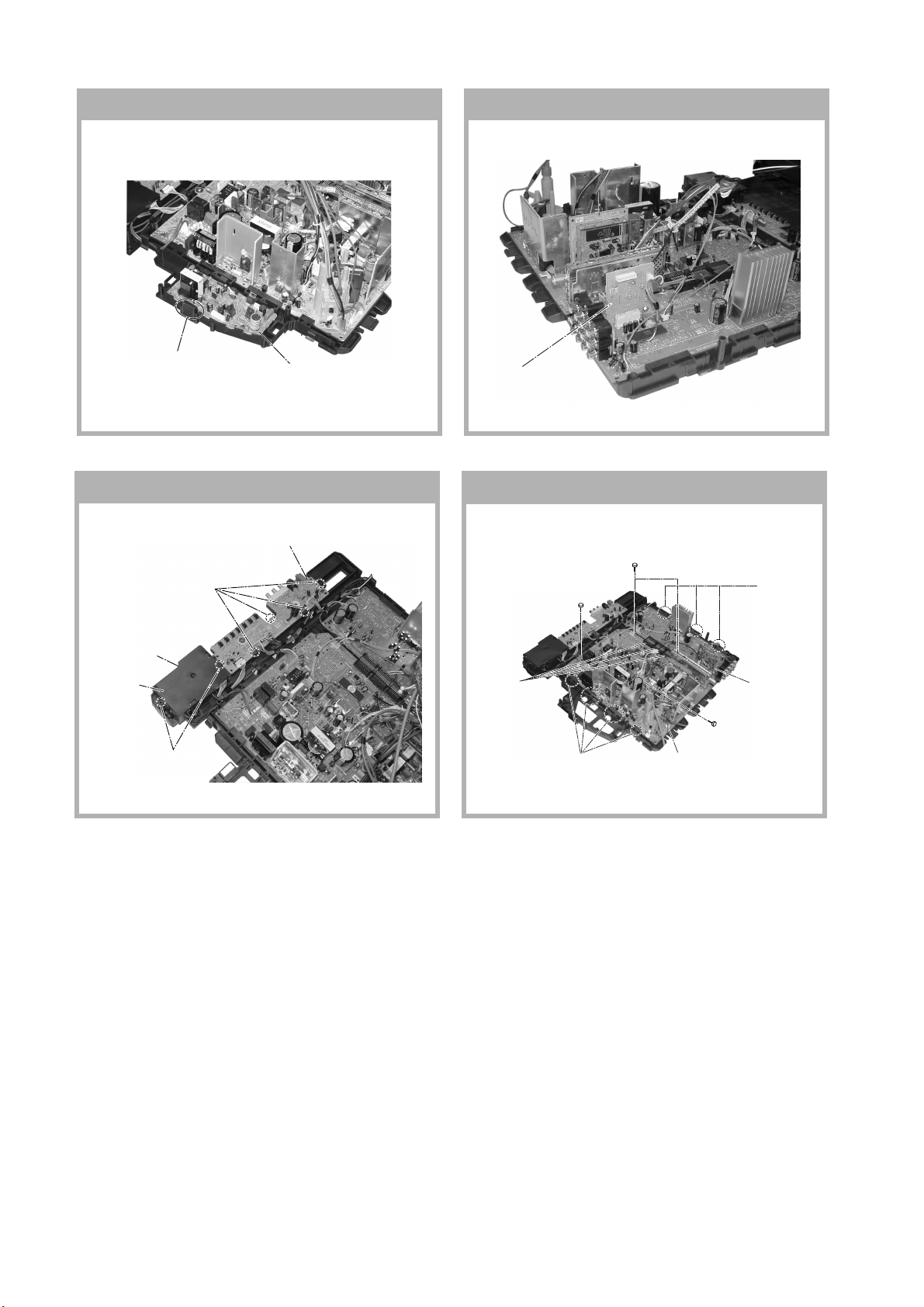
1. DISASSEMBLY
1-1. Rear Cover Removal ................................................... 7
1-2. Speaker Removal ........................................................ 7
1-3. Chassis Assy Removal ................................................ 7
1-4. F Board Removal ........................................................ 7
1-5. Service Position .......................................................... 7
1-6. Terminal Bracket and J Board Removal .................... 7
1-7. D3 Board Removal ..................................................... 8
1-8. B1 Board Removal ...................................................... 8
1-9. H1 and H2 Boards Removal ....................................... 8
1-10. A and B10 Boards Removal ....................................... 8
1-11. Picture Tube Removal ................................................. 9
2. ADVANCE OPERATION
2-1. "RESET" Function .................................................... 10
3. SET-UP ADJUSTMENTS
3-1. Beam Landing ........................................................... 11
3-2. Convergence .............................................................. 12
3-3. Focus Adjustment ..................................................... 14
3-4. G2 (SCREEN) and White Balance Adjustment ....... 15
4. CIRCUIT ADJUSTMENTS
4-1. Adjustment With Commander .................................. 16
4-2. Adjustment Method .................................................. 16
4-3. Adjustment for Non Digital Texture Enchancer
(DTE) Model ............................................................. 24
4-4. Adjustment for Digital Texture Enchancer
(DTE) Model ............................................................. 24
4-5. Display Position Adjustment .................................... 25
4-6. Deflection Adjustment .............................................. 25
4-7. Picture Distortion Adjustment .................................. 26
Section Title Page Section Title Page
5. DIAGRAMS
5-1. Block Diagram .......................................................... 27
5-2. Circuit Boards Location ........................................... 29
5-3. Schematic Diagram ................................................... 30
(1) C6 Board Schematic Diagram ............................ 31
(2) A Board Schematic Diagram .............................. 33
(3) B10 Board Schematic Diagram .......................... 37
(4) B1 and D3 Boards Schematic Diagrams ............ 39
(5) F and VM1 Boards Schematic Diagrams ........... 41
(6) H1 Board Schematic Diagram ............................ 43
(7) J Board Schematic Diagram ............................... 45
(8) H2 Board Schematic Diagram ............................ 46
5-4. Voltage List and Waveforms ..................................... 48
5-5. Printed Wiring Boards and Parts Location ............... 53
5-6. Semiconductors ......................................................... 61
6. EXPLODED VIEWS
6-1. Speaker Bracket ........................................................ 62
6-2. Chassis ...................................................................... 63
6-3. Picture Tube .............................................................. 64
7. ELECTRICAL PARTS LIST......................................... 65
OPERATING MANUAL

–4 –
KV-AR29M90
RM-993
The units in this manual contain a self-diagnostic function. If an error occurs, the STANDBY/TIMER lamp will automatically
begin to flash.
The number of times the lamp flashes translates to a probable source of the problem. A definition of the STANDBY/TIMER
lamp flash indicators is listed in the instruction manual for the user’s knowledge and reference. If an error symptom cannot
be reproduced, the remote commander can be used to review the failure occurrence data stored in memory to reveal past
problems and how often these problems occur.
1. DIAGNOSTIC TEST INDICATORS
When an errors occurs, the STANDBY/TIMER lamp will flash a set number of times to indicate the possible cause of the
problem. If there is more than one error, the lamp will identify the first of the problem areas.
Result for all of the following diagnostic items are displayed on screen. No error has occured if the screen displays a “0”.
Diagnostic
Item
Description
•Power does not
turn on
•+B overcurrent
(OCP) or
overvoltage
(OVP)
•Vertical deflection
stopped
•Horizontal
deflection
overdrive
•White balance
failure (no
PICTURE)
•Micro reset
Detected
Symptoms
•Power does not come on.
•No power is supplied to the
TV.
•AC power supply is faulty.
•Power does not come on.
•Load on power line is
shorted.
•Has entered standby state
after horizontal raster.
•Vertical deflection pulse is
stopped.
•Power line is shorted or
power supply is stopped.
•No raster is generated.
•CRT cathode current
detection reference pulse
output is small.
•Power is shut down shortly,
after this return back to
normal.
•Detect Micro latch up.
Note 1: If a + B overcurrent is detected, stoppage of the vertical deflection is detected simultaneously.
The symptom that is diagnosed first by the microcontroller is displayed on the screen.
Note 2: Refer to screen (G2) Adjustment in section 3-4 of this manual.
* R(Q703), G(Q702) or B(Q701) out is faulty (C6 board).
SELF DIAGNOSTIC FUNCTION
No. of times
STANDBY/TIMER
lamp flashes
Does not light
2 times
5 times
—
Self-diagnostic
display/Diagnostic
result
—
002:000 or
002:001~255
003:001~255
004:001~255
at the same time
005:000 or
005:001~225
101:00 or
101:001~225
Probable
Cause
Location
•Power cord is not plugged
in.
•Fuse is burned out F4601
(F)
•H.OUT Q511 is shorted.
(A board)
•Q701, Q702, Q703 is
shorted (C6 board)
•-13V is not supplied.
(A board)
•IC 503 faulty (A board)
•G2 is improperly adjusted.
(Note 2)
•CRT problem.
•R(Q703), G(Q702) or
B(Q701) out is faulty
(C6 board)
•IC301 is faulty. (A board)
•No connection A board to
C6 board.
•Discharge CRT (C6 Board)
•Static discharge
•External noise

–5 –
KV-AR29M90
RM-993
2. DISPLAY OF STANDBY/TIMER LIGHT FLASH COUNT
3. STOPPING THE STANDBY/TIMER FLASH
Turn off the power switch on the TV main unit or unplug the power cord from the outlet to stop the STANDBY/TIMER lamp
from flashing.
4. SELF-DIAGNOSTIC SCREEN DIPLAY
For errors with symptoms such as “power sometimes shuts off”or “screen sometimes goes out”that cannot be confirmed, it
is possible to bring up past occurances of failure for confirmation on the screen:
[To Bring Up Screen Test]
In standby mode, press buttons on the remote commander sequentially in rapid succession as shown below:
[Screendisplay] /channel [5] /Sound volume [-] /Power ON
˘
Note that this differs from entering the service mode (mode volume [+]).
Self-Diagnosis screen display
Diagnostic Item Flash Count*
+B overcurrent/overvoltage 2 times
Vertical deflection stopped
White balance failure 5 times
* One flash count is not used for self-diagnostic.
2 times
3 times
Lamp ON 0.3 sec.
Lamp OFF 0.3 sec. Lamp OFF 3 sec.
002 : 000
003 : 000
004 : 000
005 : 001
101 : 000
SELF DIAGNOSTIC
Numeral "0" means that no fault has been detected.
Numeral "1" means a fault has been detected.
STANDBY/SLEEP lamp

–6 –
KV-AR29M90
RM-993
5. HANDLING OF SELF-DIAGNOSTIC SCREEN DISPLAY
Since the diagnostic results displayed on the screen are not automatically cleared, always check the self-diagnostic screen
during repairs. When you have completed the repairs, clear the result display to “0”.
Unless the result display is cleared to “0”, the self-diagnostic function will not be able to detect subsequent faults after
completion of the repairs.
[Clearing the result display]
To clear the result display to “0”, press buttons on the remote commander sequentially as shown below when the diagnostic
screen is being displayed.
Channel [8] /0
[Quitting Self-diagnostic screen]
To quit the entire self-diagnostic screen, turn off the power switch on the remote commander or the main unit.
6. SELF-DIANOSTIC CIRCUIT
[+BovercurrentªOCPº] Occurs when an overcurrent on the +B(135) line is detected by Q604. If Q604 go to ON
and the voltage to pin 18 of IC301 should go down when V.SYNC is more than seven
verticals in a period, the unit will automatically turn off.
[Verticaldeflectionstopped] Occurs when an absence of the vertical deflection pulse is detected by Q509 and IC001
shut down the power supply.
[Verticaldeflectionovercurrent] Occurs when an overcurrent on V drive line is detected by Q507. Power supply will be
shut down when detect this by IC001.
[ hitebalancefailure] If the RGB levels* do not balance or become low level within 5 seconds, this error will be
detected by IC301. TV will stay on, but there will be no picture.
* (Refers to the RGB levels of the AKB detection Ref pulse that detects IK.)
IC301
Y/CHROMA JUNGLE
FROM
CRT
[V] Q509/507
IC001
SYSTEM
IC003
MEMORY
IK-IN
MP/
PROTECT O-LED
IO-8DAT B-DAT
IO-SDAT
521
18 51
46
SDA 35
FROM
[+B] Q604 C6
45

–7 –
KV-AR29M90
RM-993
6J Board
1One screw
(+BVTP 3 × 12)
4Terminal bracket
5Two screws
(+BVTP 4 × 16)
3One screw
(+BVTP 4 × 16)
2Two Hooks
1One screw
(+BVTP 3 × 12)
3Two screws
(+BVTP 4 × 16)
1Two screws
(+BVTP 4 × 16)
2Two screws
(Washer Head) (+P4x16)
SECTION 1
DISASSEMBLY
1-1. REAR COVER REMOVAL 1-2. SPEAKER REMOVAL
1-3. CHASSIS ASSY REMOVAL 1-4. F BOARD REMOVAL
1-5. SERVICE POSITION 1-6. TERMINAL BRACKET AND J BOARD
REMOVAL
1Night screws
(+BVTP 4 × 16)
2Rear cover
1Two screw
(Washer Head) (+P4x16)
4F Board
2F Board bracket
3Two hooks

–8 –
KV-AR29M90
RM-993
1-10. A AND B10 BOARDS REMOVAL
1-9. H1 AND H2 BOARDS REMOVAL
1-7. D3 BOARD REMOVAL 1-8. B1 BOARD REMOVAL
2D3 Board
1One Hooks
2B1 Board
4Cover, H
5H2 Board
3Two hooks
1Four hooks
2H1 Board
5One screw
(3 ×12)(+)(BVTP)
2Two screws
(3 ×12)(+) BVTP
3Three hooks
6Four hooks 7A Board
5One screw
(3 ×12)(+)(BVTP)
4B10 Board
1Three connectors

–9 –
KV-AR29M90
RM-993
c
1-11. PICTURE TUBE REMOVAL
• REMOVAL OF ANODE-CAP
Note:
•After removing the anode, short circuit the anode of the picture tube and the anode cap to the metal chassis, CRT
shield or carbon paint on the CRT.
•REMOVING PROCEDURES
1Turn up one side of the rubber cap in the direction
indicated by the arrow a.
2Using a thumb pull up the rubber cap firmly in the direc-
tion indicated by the arrow b.
3When one side of the rubber cap is separated from the
anode button, the anode-cap can be removed by
turning up the rubber cap and pulling it up in the
direction of the arrow c.
•HOW TO HANDLE AN ANODE-CAP
1Do not damage the surface of anode-caps with
sharp shaped objects.
2Do not press the rubber too hard so as not to
damage the inside of anode-cap.
A metal fitting called the shatter-hook terminal is
built into the rubber.
3Do not turn the foot of rubber over too hard.
The shatter-hook terminal will stick out or damage
the rubber.
a
a
b
b
anode button
Note:
•Please make sure the TV set is not in standing posotion before removing necessary CRT support located on bottom
right and left.
1) Place the TV set with the CRT face down on a cushion jig.
2) Removal the rear cover.
qs Nut, locking
8Holder, DGC(2)
Removal
q; Spring Tension(2)
Removal
5Loosen the Neck Assembly
fixing screw and removal
4VM1 Board Removal
6Chassis Assy Removal
2C6 Board Removal
3Loosen the Neck Assembly
fixing screw and removal
9Degaussing Coil
7Band, DGC Removal
1Anode Cap Removal
qa Earth Coating Assy

–10 –
KV-AR29M90
RM-993
SECTION 2
ADVANCE OPERATION
2-1. "RESET" FUNCTION
1. Purpose
If a customer faces some setting problem that cannot be solved, using the "RESET" function some items will
be reset to its original setting (shipment condition)
2. How to Operate
The way to access to the "RESET" Function:-
a) By pressing "MENU" button or "SELECT" button (for non-menu models) on the Front Key Input and
hold it down for 5 seconds.
3. Subsequent of Operation
Sequential to the resetting operation (either methods being used in No. 2), TV set would shut down once and
automatically turn on again. The power-off duration is expected to be about 500msec. An OSD message,
"RESET" tentatively will be displayed for 10 sec after IK status gets stable.
As a result, some items will be reset to an initial condition (shipment condition) wheareas some other remains
at the last selection by user.
Items that remains at the last selection by user
Reset Items
Channel No., Favourite CH Setup,
PIC rotation, OSD Language, Fine tuning, TV System, Skip
*= only when in RF mode
Video input RF
Volume 30
Picture mode DYNAMIC
PICSI
Sound mode DYNAMIC
Surround mode OFF
Favourite CH mode AUTO
Multi Picture (PIP) OFF
PIP position Bottom Right
OSD recall OFF
Antenna sensitivity OFF
Antenna sensitivity HIGH*
Stereo mode STEREO
Bilingual mode MAIN*
High-deviation mode AUTO
Child lock OFF*
Wide mode OFF
Game mode OFF
Sleep timer OFF
Wake-up timer OFF
Sound muting OFF

–11 –
KV-AR29M90
RM-993
•The following adjustments should be made when a complete
realignment is required or a new picture tube is installed.
•These adjustments should be performed with rated power
supply voltage unless otherwise noted.
Controls and switches should be set as follows unless otherwise noted:
PICTURE control ........................................................... normal
BRIGHTNESS control ................................................... normal
Perform the adjustments in the following order :
1. Beam Landing
2. Convergence
3. Focus
4. White Balance
Note : Test Equipment Required.
1. Pattern Generator
2. Degausser
3. Oscilloscope
SECTION 3
SET-UP ADJUSTMENTS
normal
Preparation :
•In order to reduce the influence of geomagnetism on the set's
picture tube, face it east or west.
•Switch on the set's power and degauss with the degausser.
3-1. BEAM LANDING
1. Input a white signal with the pattern generator.
Contrast
Brightness
2. Position neck assy as shown in Fig3-2.
3. Set the pattern generator raster signal to a green raster.
4. Move the deflection yoke to the rear and adjust with the
purity control so that the green is at the center and the blue
and the red take up equally sized areas on each side.
(See Figures 3-1 through 3-4.)
5. Move the deflection yoke forward and adjust so that the
entire screen is green. (See Figure 3-2.)
6. Switch the raster signal to blue, then to red and verify the
condition.
7. When the position of the deflection yoke has been decided,
fasten the deflection yoke with the screws and DY spacers.
8. If the beam does not land correctly in all the corners, use a
magnet to adjust it.
(See Figure 3-5.)
}
Fig. 3-1 Fig. 3-2
Fig. 3-5
Fig. 3-4
Fig. 3-3
a
b
b
c
c
d
d
a
Purity control
corrects this area. Disk magnets or rotatable
disk magnets correct these
areas (a-d).
Deflection yoke positioning
corrects these areas.
Neck Assy
Behind the G2 edge
○○○○○○○○○○○○○○○○○○○○○○○○○○○○○○○○○○○○○○○○○○○○○○○○○○○○○○○○○○○○○○○
Red
Blue
Green
Purity control
G2G1 G3

–12 –
KV-AR29M90
RM-993
3-2. CONVERGENCE
Preparation :
•Before starting this adjustment, adjust the focus, horizontal size
and vertical size.
•Receive dot/hatch signal.
•Pic mode: Personal (Pic 90%, Brightness 50%, Colour 50 %,
Hue 50%, Sharpness 50%).
(1) Horizontal and Vertical Static Convergence
1. (Moving horizontally), adjust the H.STAT control so that the
red, green and blue dots are on top of each other at the center of
the screen.
2. (Moving vertically), adjust the V.STAT magnet so that the red,
green and blue dots are on top of each other at the center of the
screen.
3. If the H.STAT variable resistor cannot bring the red, green and
blue dots together at the center of the screen, adjust the
horizontal convergence with the H.STAT variable resistor and
the V.STAT magnet in the manner given below.
(In this case, the H.STAT variable resistor and the V.STAT
magnet influence each other, so be sure to perform adjustments
while tracking.)
1V. S TAT
2H. STAT VR
3
H. STAT VR
V. STST
Magnet
RV702
H. STAT
RV701
SCREEN (G2)
C6 Board
Center dot
R G B
G
R
B
Purity BMC
BMC (Hexapole)
Purity
DY pocket
V.STAT
V.STAT
a
a
a
b
b
b b
a
a
b
b
b
R
R
G
G
B
B
R
RG
GB
B
R
R
G
G
B
B

–13 –
KV-AR29M90
RM-993
5Y separation axis correction magnet adjustment.
1. Receive the cross-hatch signal and adjust [PICTURE] to [MIN]
and [BRIGHTNESS] to [STANDARD] .
2. Adjust the Y separation axis correction magnet on the neck
assembly so that the horizontal lines at the top and bottom of
the screen are straight.
Note
1. The Red and Blue magnets should be equally far from the
horizontal center line.
2. Do not separate the Red and Blue magnets too far. (Less than
8 mm)
(2) Dynamic Convergence Adjustment
Preparation:
•Before starting this adjustment, adjust the horizontal static
convergence and the vertical static convergence
4BMC (Hexapole) Magnet.
If the red, green and blue dots are not balanced or aligned, then
use the BMC magnet to adjust in the manner described below.
RG B R G B R GB
RB
RG
GGB
RB
Neck assy Neck assy
Blue
Red Blue
Red
VM1 board VM1 board
RB
RB
TLH TLV
YCH XCV
B
R
R
B

–14 –
KV-AR29M90
RM-993
(3) Screen-corner Convergence
Fix a Permalloy assy corresponding to the misconverged
areas.
3-3. FOCUS ADJUSTMENT
FOCUS adjustment should be completed before W/B adjustment.
1. Receive digital monoscope pattern.
2. Set "Picture Mode" to "Standard".
3. Set S2801 to mechanical center position.
4. Adjust focus VR so that the center of the screen becomes just
focus.
5. Adjust S2801 when corner focus is unbalance is right and left.
6. Change the receiving signal to white pattern blue back.
7. Confirm Magenta ring is not noticable. Incase magneta ring is
obvious, reset S2801 to mechanical center position and then
adjust FOCUS VR to balance between MAGENTA RING and
FOCUS.
TLV Rotate TLV-2 VOL (29”, 34”) on DY
XCV Rotate XCV Adj core on DY
YCH Rotate YCH VOL on DY
TLH Insert TLH Correction Plate to DY Pocket
(Left or Right)
ON DY:
FLYBACK TRANSFORMER (T503)
YCH
XCV
TLV1
TLV2
ba
cd
a-d : screen-corner
misconvergence
a
b
c
d
Permalloy assembly
Focus
Screen

–15 –
KV-AR29M90
RM-993
2. WHITE BALANCE ADJUSTMENT
1) Set to Service Mode (Refer Section 4-1: ADJUSTMENTS
WITH COMMANDER).
2) Input white raster signal.
3) Set the PICTURE to minimum.
4) Select GCT (WHB 4) and BCT (WHB 5) with [1] and [4], and
adjust the level with [3] and [6] for the best white balance.
5) Set the PICTURE to maximum.
6) Select GDR (WHB 1) and BDR (WHB 2) with [1] and [4],
and adjust the level with [3] and [6] for the best white
balance.
7) Write into the memory by pressing [MUTING] then [0].
3. SUB BRIGHT ADJUSTMENT
1) Set to service mode.
2) Input a staircase signal of black to white from the pattern
generator.
3) BRIGHTNESS .... 50%.
PICTURE ............ MINIMUM
4) Select SBR (WHB7) with [1] and [4], and adjust SBR
(WHB7) level with [3] and [6] so that the second stripe from
the right is dimly lit.
3-4. G2 (SCREEN) AND WHITE BALANCE
ADJUSTMENTS
1. G2 (SCREEN) ADJUSTMENT
1) Set the PICTURE to normal.
2) Put to VIDEO input mode without signals.
3) Connect R, G and B of the C6 board cathode to the
oscilloscope.
4) Adjust BRIGHTNESS to obtain the cathode voltage to the
value below.
5) Adjust G2 (screen) on the FBT until picture shows the point
before cut off.
0 V
Cathode setting voltage:
175 V ±2 (VDC)
second from the right
Black
White

–16 –
KV-AR29M90
RM-993
SECTION 4
CIRCUIT ADJUSTMENTS
4-1. ADJUSTMENTS WITH COMMANDER
Service adjustments to this model can be performed using the
supplied Remote Commander RM-993.
a. ENTERING SERVICE MODE
With the unit on standby
This operation sequence puts the unit into service mode.
The screen display is :
b. METHOD OF CANCELLATION FROM SERVICE
MODE
Set the standby condition (Press [PO ER] button on the commander),
then press [PO ER] button again, hereupon it becomes TV mode.
c. METHOD OF WRITE INTO MEMORY
1) Set to Service Mode.
2) Press [1] (UP) and [4] (DOWN), to select the adjustment.
4) Press [MUTING] button to indicate WRITE on the screen.
5) Press [0] button to write into memory.
d. MEMORY WRITE CONFIRMATION METHOD
1) After adjustment, pull out the plug from AC outlet, and then
plug into AC outlet again.
2) Turn the power switch ON and set to Service Mode.
3) Call the adjusted items again to confirm adjustments were made.
n[DISPLAY] n5nVOL (+) n[PO ER]
4-2. ADJUSTMENT METHOD
Item Number 00 of device GEO
This explanation uses H-Position as an example.
1. Select “GEO 00 HPS”with the 1and 4buttons.
2. Raise/lower the data with the 3and 6buttons.
3. Select the optimum state. (The standard is 1F for PAL
reception.)
4. Write with the [MUTING] button. (The display changes to
WRITE.)
5. Execute the writing with the -button. (The WRITE
display will be changed to red color while excuting, and
back to SERVICE.)
Example on screen display :-
1, 4Select the adjustment item.
↓
3, 6Raise/lower the data value.
↓
[MUTING] Writes.
↓
-Executes the writing.
7, -All the data becomes the values in memory.
8, -All user control goes to the standard state.
5, -Service data initialization (Be sure not to use
usually.)
[MUTING]+ -Write 50Hz adjustment data to 60Hz, or vice
versa.
2, -Copy and write all data.
Use the same method for all Items. Use 1and 4to select the
adjustment item, use 3and 6to adjust, write with [MUTING],
then execute the write with -.
Note :1.In[ RITE], the data for all items are written into
memory together.
2. For adjustment items that have different standard data
between 50Hz or 60Hz, be sure to use the respective
input signal after adjustment.
PAL,SECAM:50
NTSC :60
00
HPS 1C pGEO
1.0C
59 7F 000A0602S
Device
Name
Suffix No
(OEM Code)
Item
Name Marking of new NVM
Item No
Software version Total Power-On time (hours)
Data Mode
1F 50HPS
GEO 00
7F 0 000A59
602S 1.0C
1F WRITE 50HPS
GEO 00
7F 0 000A59
602S 1.0C
1F 50HPS
GEO 00
7F 0 000A59
602S 1.0C
GREEN
Write with [MUTING]
Write executed with -
GREEN
RED
The WRITE display
then the display
returns to green
SERVICE.
Adjusted with 3
and 6buttons.

–17 –
KV-AR29M90
RM-993
Adjustment Item Table
GVT ytilanoitcnuF oN
ceD
laitinI egnaR noitcnuF etoN&elbaT .oNretsigeR
)egnaRtiB(
emaNeciveD
)sserddAevalS(
sserddAMAR
)egnaRtiB(
sserddAMVN :skrameR
yrogetaC .oN emaN evalS buS tiB selbatrofatadlaitinI
OEG00SPH0E1F3noitisoPH })06/05(ediW/)06/05(lamroN{srehtO:ORN)2-7(41)H88(S9512AXC)2-7(E96A)17/F6(/)D6/B6(2-7)zH06rof(E1
10ZSH152F3eziSH )06/05(ediW/)06/05(lamroN)2-7(31)2-7(D94A/0A)E4/34(/)DA/0A(2-7lacipyt
20PAP2F1F3pmAniP )06/05(ediW/)06/05(lamroN)2-7(51)2-7(F94A/0A)05/54(/)FA/2A(2-7lacipyt
30TLT37F0muizeparT )06/05(ediW/)06/05(lamroN)4-7(71)4-7(1A4A/0A)25/74(/)1B/4A(4-7lacipyt
40SPV4F1F3noitisoPV )06/05(ediW/)06/05(lamroN)2-7(11)2-7(B94A/0A)C4/14(/)BA/E9(2-7lacipyt
50ZSV5F1F3ezisV )06/05(ediW/)06/05(lamroN)2-7(01)2-7(A94A/0A)B4/04(/)AA/D9(2-7lacipyt
60OCS67F0noitcerroCS )06/05(ediW/)06/05(lamroN)4-7(21)4-7(C94A/0A)D4/24(/)CA/F9(4-7lacipyt
70NLV77F0ytiraeniLV )06/05(ediW/)06/05(lamroN)0-3(21)0-3(C94A/0A)D4/24(/)CA/F9(0-3lacipyt
80WOB87F0woBCFA )06/05(ediW/)06/05(lamroN)4-7(81)4-7(2A4A/0A)35/84(/)2B/5A(4-7lacipyt
90LGA97F0elgnACFA )06/05(ediW/)06/05(lamroN)0-3(81)0-3(2A4A/0A)35/84(/)2B/5A(0-3lacipyt
A0NPU01F1F3niPreppU )06/05(ediW/)06/05(lamroN)2-7(61)2-7(0A4A/0A)15/64(/)0B/3A(2-7lacipyt
B0NPL11F1F3niPrewoL )06/05(ediW/)06/05(lamroN)2-7(A1)2-7(4A4A/0A)55/A4(/)4B/7A(2-7lacipyt
C0 LBH2111 ffo/nogniknalBH srehtO:ORN)1(A1)1(476A371 lacipyt
D0 LBL31B0F0gniknalBHtfeL })06/05(ediW/)06/05(lamroN{srehtO:ORN)4-7(91)4-7(3A6A)27/07(/)E6/C6(4-7)zH06rof(F0
E0 LBR412F0gniknalBHthgiR })06/05(ediW/)06/05(lamroN{srehtO:ORN)0-3(91)0-3(3A6A.)27/07(/)E6/C6(0-3lacipyt
BHW00RDR052F3evirDR srehto/CIMANYD)2-7(B0)H88(S9512AXC)2-7(E730AAB/0C2-7)CIMANYD-nonrof(A2
10RDG152F3evirDG srehto/CIMANYD)2-7(C0)2-7(F730ABB/1C2-7lacipyt
20RDB252F3evirDB srehto/CIMANYD)2-7(D0)2-7(0830ACB/2C2-7lacipyt
30 TCR37F0ffotuCR srehto/MACES)0-3(90)0-3(2830ADB/3C0-3lacipyt
40TCG47F0ffotuCG srehto/MACES)4-7(A0)2-7(3830AEB/4C4-7lacipyt
50TCB57F0ffotuCB srehto/MACES)0-3(A0)0-3(3830AEB/4C0-3lacipyt
60 NMB651F1ataDmuminiMssenthgirB )2-7(80)2-6(6010A222-6-
70RBS752F3lortnoCssenthgirBbuS )2-7(80)2-7(7010A322-7-
80BPA 803 3#erutciPtnegilletnIrofhctiwSlortnoCthgirBbuS )2-7(80)0-1(7010A320-1-
JAS00XMP083F3ataDmumixaMerutciP ediW/ediW-non)2-7(50)H88(S9512AXC)2-7(5010A02/122-7lacipyt
10UHS17F0lortnoCeuHbuS oediV/VT)2-7(70)2-5(8010A83/422-5lacipyt
20 HSS25F0lortnoCssenprahSbuS oediV/VT)4-7(90)2-7(9010A63/524-7)OEDIVrof(90
30LCS3F1F3lortnoCroloCbuS )srehto/CSTN(EDIW/)srehto/CSTN()2-7(60)2-7(A010A)B3/C3(/)62/73(2-7lacipyt

–18 –
KV-AR29M90
RM-993
GVTytilanoitcnuF.oN
ceD
laitinIegnaRnoitcnuFetoN&elbaT.oNretsigeR
)egnaRtiB(
emaNeciveD
sserddAevalS
sserddAMAR
)egnaRtiB(
sserddAMVN:skrameR
yrogetaC.oNemaN evalSbuStiBselbatrofatadlaitinI
PV00THE05F0pmoCTHE zH06/05)0-3(71)H88(S9512AXC)0-3(1A]4A/[0A])25/74(/[1B/4A0-3lacipyt
10 AMG123 )edomDRADNATSnidetatapes(noitcerroCammaG )srehto/CSTN(DTS/)srehto/CSTN(DTS-NON)0-1(D0)0-1(7634A96/A6/76/860-1lacipyt
20GPA201 3#erutciPtnegilletnIrofhctiwSlortnoCammaG )srehto/CSTN(DTS/)srehto/CSTN(DTS-NON)0-1(D0)2(7634A96/A6/76/862 -
30 LDY36F0yaleDY DVD/CSTN/MACES/LAP)0-3(E0)0-3(C634AF3/D3/E3/C30-3)DVD/CSTN/MACESrof80/80/90(
40 TSS413 noitisoPtratSDIMACES CSTN&LAP-DECROF/OTUTA&MACES)4-5(30)4-5(9634AD6/B64-5)CSTN/LAPdecrofrof00(
50 PSS513 noitisoPpotSDIMACES CSTN&LAP-DECROF/OTUTA&MACES)6-7(30)6-7(9634AD6/B66-7)CSTN/LAPdecrofrof30(
60 MLR603 timiLBGR )0-1(30)0-1(D50A380-1lacipyt
70 VLS723OleveLDIMACES CSTN&LAP-DECROF/OTUTA&MACES)0-1(40)0-1(A634AE6/C60-1)CSTN/LAPdecrofrof20(
80FBS822F3OfLLEBMACES CSTN&LAP-DECROF/OTUTA&MACES)2-7(40)2-7(A634AE6/C62-7)CSTN/LAPdecrofrof22(
90 CYD911 ffo/noroloCcimanyD )1(C0)1(660AC81 -
A0 LBA0111 )edomDRADNATStpecxe(gnihctiwSedoMLBA DRADNATStpecxe)1(B0)1(560AB81 )DRADNATSrof00(
B0 HTV1111 gnihctiwShtVnoitceteDLBA )0(B0)0(560AB80 -
C0 0FS2111 ssenprahSrofgnihctiwSOF srehto/CSTN)1(70)1(A534A95/C51 lacipyt
D0 XCD3111 gnihctiwSoitaR.snarTCD )1(80)1(260A881 -
E0 THS4111 hctiwSoitartoohsrevO/-erP srehto/CSTN)0(80)0(B534AA5/D50 lacipyt
F0 WDH5101 hctiwShtdiWesluPevirDH )6(00)6(A50A086 -
01 CFA611 3OlortnoCniaGCFA txeT/oediV/VT)0-1(11)0-1(7A0AA2/92/820-1)TXET/OEDIVrod10/00(
11SOH717 F0noitallicsOH )4-7(E0)4-7(860AE84-7-
21 SSH8101 .peScnySHfoleveLecilS )1(F0)1(960AF81 -
31 SSV9101 .peScnySVfoleveLecilS )0(F0)0(960AF80 -
41 SMH0211 no/ffom/CnoisiVorcaM zH06/05)0(01)0(A9]4A/[0A])B4/04(/[AA/D90 lacipyt
51 VUY1201 LESY )2(00)2(A50A082 -
61 VDC2213 langisonrednuFRdnaoedivrofedomDC ylnooediv)4-5(F0)4-5(5630AB24-5-
71 NOR3211 NOR deziromemton)2(10)2(B50A182 desiromemton
81 NOG4211 NOG deziromemton)1(10)1(B50A181 desiromemton
91 NOB5211 NOB deziromemton)0(10)0(B50A180 desiromemton
A1 NOP6211 NOP deziromemton)7(00)7(A50A087 desiromemton
B1 NXA7211 WSSIXA )CIMANYDrofylno(srehto/CSTN)0(70)0(A010A])B3/C3(/[62/730 -
C1 LSR8201 LESBGR )0(C0)0(660AC80 -
D1 WBV9203 WKLBV )0-1(61)0-1(070A690-1-
E1 PFR0301 PFER )0(41)0(E60A490 -
F1 CMV1303 leveLMV )2-3(30)2-3(D60A382-3-
02 FBC2301 retliFssapdnaBamorhC
12 OTC3301 ffOparTamorhC
Table of contents
Other Sony TV manuals

Sony
Sony TRINITRON KV-32FV27 User manual

Sony
Sony KV-XS29M31 User manual

Sony
Sony BRAVIA KLV-40R352E User manual

Sony
Sony KV-SR29 User manual

Sony
Sony BRAVIA XR-85X9xJ User manual

Sony
Sony KDL-32W4000 User manual

Sony
Sony KV-25FXR20 User manual

Sony
Sony KD-65S8500D User manual

Sony
Sony KDL-22S5500 User manual

Sony
Sony KP-48PS2 User manual

Sony
Sony TRINITRON KV-T29SN81 User manual

Sony
Sony BRAVIA KD-49X70 Series User manual

Sony
Sony Trinitron KV-20V50 User manual

Sony
Sony KV-29FQ85 User manual

Sony
Sony Bravia KDL-40HX75A User manual

Sony
Sony KV-V28 User manual

Sony
Sony TRINITRON KV-29FV16A User manual

Sony
Sony TRINITRON KV-VF21M40 User manual

Sony
Sony TRINITRON KV-21M3A User manual

Sony
Sony Bravia KDL-40Z5800 User manual