Sound Sation CLARITY S-10 User manual
CLARITY
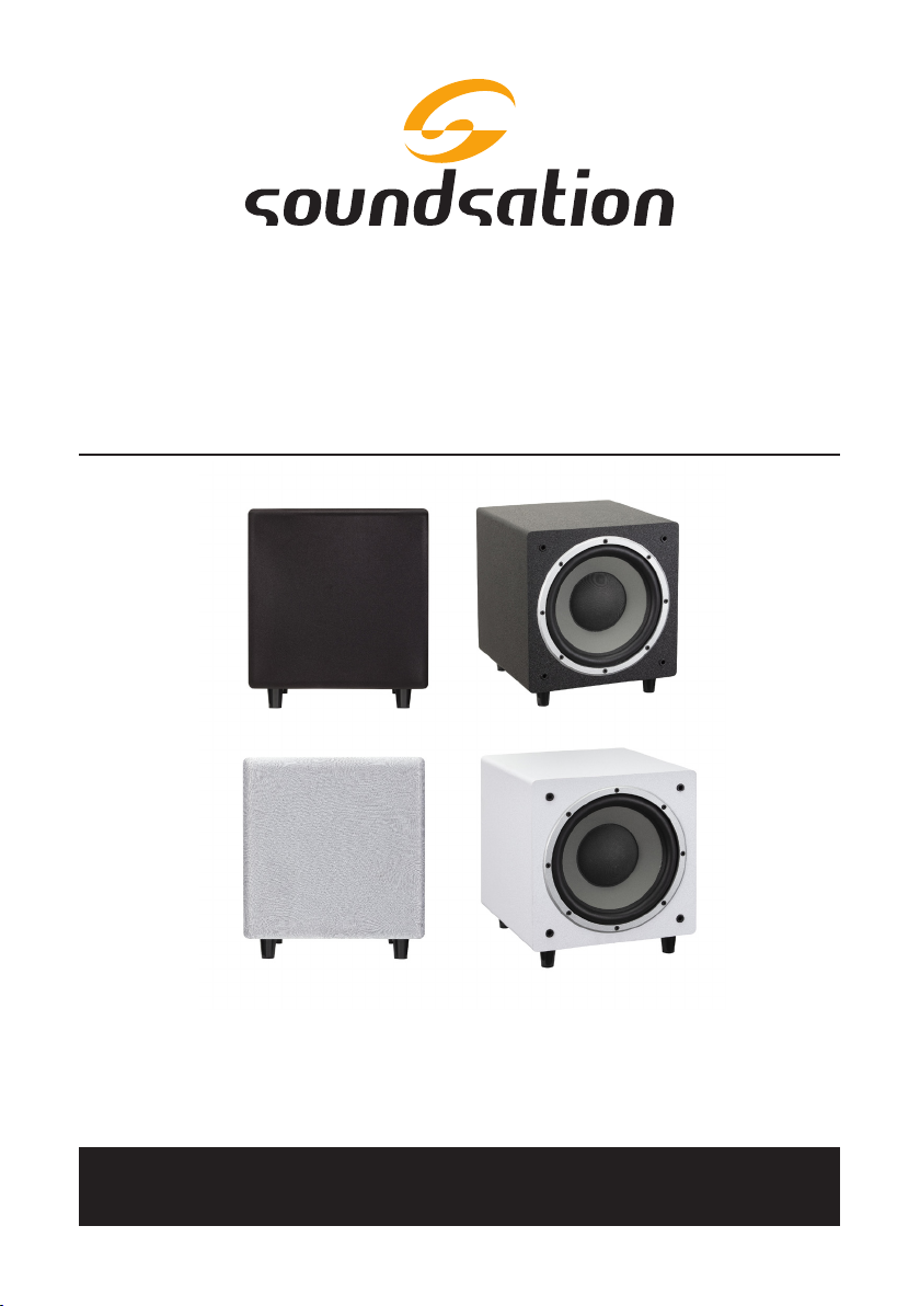
S-10 / S-10-W
Active Studio SubWooFer
Please read this manual carefully and properly take care of it
USER MANUAL
Leggete questo manuale e conservatelo per future consultazioni
MANUALE UTENTE

Dear customer,
First of all thanks far purchasing a SOUNDSATION® product. Our mission is to satisfy
all possible needs of musical instrument and professional audio users oering a wide
range of products using the latest technologies.
We hope you will be satised with this item and, if you want to collaborate, we are
looking for a feedback from you about the operation of the product and possible
improvements to introduce in the next future. Go to our website www.soundsation-
music.com and send an e-mail with your opinion, this will help us to build instruments
ever closer to customer’s real requirements.
One last thing: read this manual before using the instrument, an incorrect operation
can cause damages to you and to the unit. Take care!
The SOUNDSATION Team
Gentile Cliente,
Grazie per aver scelto un prodotto SOUNDSATION®. La nostra missione è quella di
orire ai nostri utenti una vasta gamma di strumenti musicali ed apparecchiature audio
e lighting con tecnologie di ultima generazione.
Speriamo di aver soddisfatto le vostre aspettative e, se voleste collaborare, saremmo
lieti di ricevere un vostro feedback sulla qualità del prodotto al ne di migliorare co-
stantemente la nostra produzione. Visitate il nostro sito www.soundsationmusic.com ed
inviateci una mail con la vostra opinione, questo ci aiuterà a sviluppare nuovi prodotti
quanto più vicini alle vostre esigenze.
Un’ultima cosa, leggete il presente manuale al ne di evitare danni alla persona ed al
prodotto, derivanti da un utilizzo non corretto.
Il Team SOUNDSATION

3
ENGLISH
TABLE OF CONTENTS
1. UNPACKING..................................................................................................6
2. OVERVIEW ....................................................................................................6
2.1. Main Features .....................................................................................................................................6
3. MAINS CONNECTION..................................................................................7
4. AUDIO CONNECTIONS ................................................................................7
4.1. RCA Unbalanced Cables .................................................................................................................7
4.2. TS JACK 1/4” Balanced Cables......................................................................................................8
4.3. XLR Balanced Cables........................................................................................................................8
5. REAR PANEL .................................................................................................9
6. SPECIFICATIONS.........................................................................................11
7. WARRANTY AND SERVICE........................................................................12
8. WARNING ...................................................................................................13
4
ENGLISH
CLARITY S-10 User manual
IMPORTANT SAFETY SYMBOLS
The symbol is used to indicate that some hazardous live terminals are
involved within this apparatus, even under the normal operating con-
ditions, which may be sucient to constitute the risk of electric shock
or death.
The symbol is used in the service documentation to indicate that spe-
cic component shall be replaced only by the component specied in
that documentation for safety reasons.
Protective grounding terminal
Alternating current/voltage
Hazardous live terminal
Denotes the apparatus is turned on
Denotes the apparatus is turned o
WARNING: Describes precautions that should be observed to prevent the danger
of injury or death to the operator.
CAUTION: Describes precautions that should be observed to prevent danger of
the apparatus.
IMPORTANT SAFETY INSTRUCTIONS
fRead these instructions
fKeep these instructions
fHeed all warning
fFollow all instructions
1)^Water and Moisture
The apparatus should be protected from moisture and rain and can not be used near
water; for example near a bathtub, a kitchen sink, a swimming pool, etc.
2)^Heat
The apparatus should be located away from heat sources such as radiators, stoves or
other appliances that produce heat.

5
ENGLISH
CLARITY S-10 User manual
3)^Ventilation
Do not block areas of ventilation opening. Failure to do could result in re. Always
install according to the manufacturer's instructions.
4)^Object and Liquid Entry
Objects do not fall into and liquids are not spilled into the inside of the apparatus for
safety.
5)^Power Cord and Plug
Protect the power cord from being walked on or pinched particularly at plugs, conve-
nience receptacles, and the point where they exit from the apparatus. Do not defeat
the safety purpose of the polarized or grounding-type plug. A polarized plug has two
poles; a grounding-type plug has two poles and a third grounding terminal. The third
prong is provided for your safety. If the provided plug does not t into your outlet,
refer to an electrician for replacement.
6)^Power Supply
The apparatus should be connected to the power supply only of the type as marked on
the apparatus or described in the manual. Failure to do could result in damage to the
product and possibly the user. Unplug this apparatus during lightning storms or when
unused for long periods of time.
7)^FUSE
To prevent the risk of re and damaging the unit, please use only of the recommend-
ed fuse type as described in the manual. Before replacing the fuse, make sure the unit
turned o and disconnected from the AC outlet.
8)^Electrical Connection
Improper electrical wiring may invalidate the product warranty.
9)^NOISE And INTERFERENCES
Do not use the device in the nearby of a TV, radio, stereo equipment, mobile phone, or
other electric devices. Otherwise, the device, TV, or radio may generate noise.
10)^Cleaning
Clean only with a dry cloth. Do not use any solvents such as benzol or alcohol.
11)^Servicing
Do not implement any servicing other than those means described in the manual. Refer
all servicing to qualied service personnel only. Only use accessories/attachments or
parts recommended by the manufacturer.

6
ENGLISH
CLARITY S-10 User manual
1. UNPACKING
Thank you for purchasing the CLARITY Studio Subwoofer. Each unit has been well test-
ed and shipped in perfect operating conditions. Carefully unpack the carton and check
the contents to ensure that all parts are present and in good conditions:
f1 x CLARITY Studio Subwoofer
f1 x Power Cable
fThis User manual
If anything damaged during transport, notify the shipper immediately and keep pack-
ing material for inspection. Again, please save its carton and all packing materials. If the
unit must be returned to the manufacturer, it is important that the unit is returned in
the original manufacturer’s packing. Please do not take any action without rst contact-
ing us.
2. OVERVIEW
The 10” CLARITY S-10 active studio subwoofer has been designed to oer musicians,
sound technicians and music producers a deep and dynamic response at low frequen-
cies and therefore precise and clear bass in the sound for a full musical experience
with 350 watts of class AB amplication. The wide choice of inputs positioned on the
rear panel (XLR, 1/4 “TS , RCA) guarantees ease of use. The modern and rened design
and the satin black nish make this studio subwoofer elegant and suitable for many
environments.
2.1. Main Features
fActive Subwoofer
f350W RMS output power
fAB Class Amplier
f30Hz - 150Hz Frequency response at -10dB
f10“ Woofer
fAttenuation adjustment of High Frequencies (from 80Hz to 120Hz).
fAttenuation adjustment of Low Frequencies (from 80Hz to 120Hz)
fBalanced 1/4 “TS / XLR and unbalanced RCA inputs
fSatin nish in black or white depending on the purchased model
fRugged MDF Case
7
ENGLISH
CLARITY S-10 User manual
3. MAINS CONNECTION
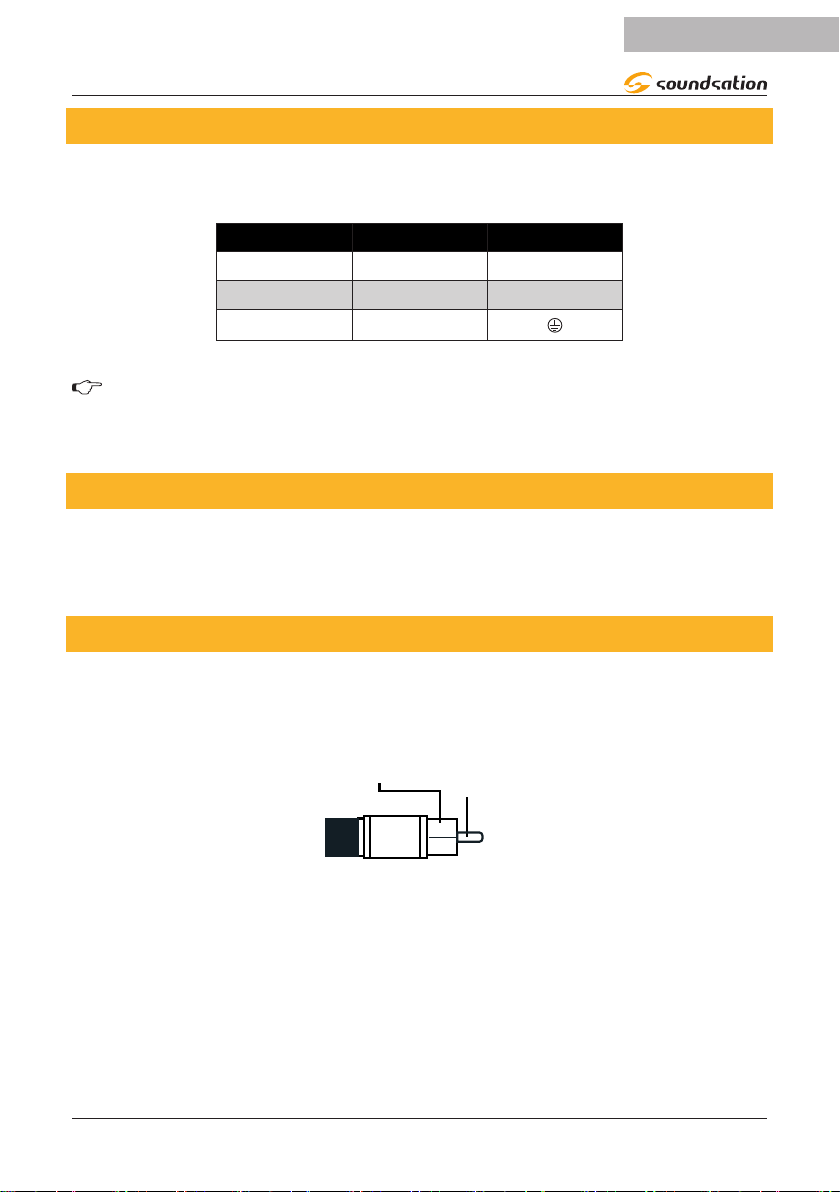
Connect the device to mains with the supplied power cable. The wire correspondence is
as follow:
Cable Pin International
Brown Live L
Blue Neutral N
Yellow/Green Earth
WARNING: Earth wire must always be connected! Pay attention to safety!
Before taking into operation for the rst time, the installation has to be ap-
proved by an expert.
4. AUDIO CONNECTIONS
On the rear panel of the monitor there are various types of audio connections which
guarantee ease of use. See the following pictures that show the internal wiring of these
cables. Be sure to use only high quality cables.
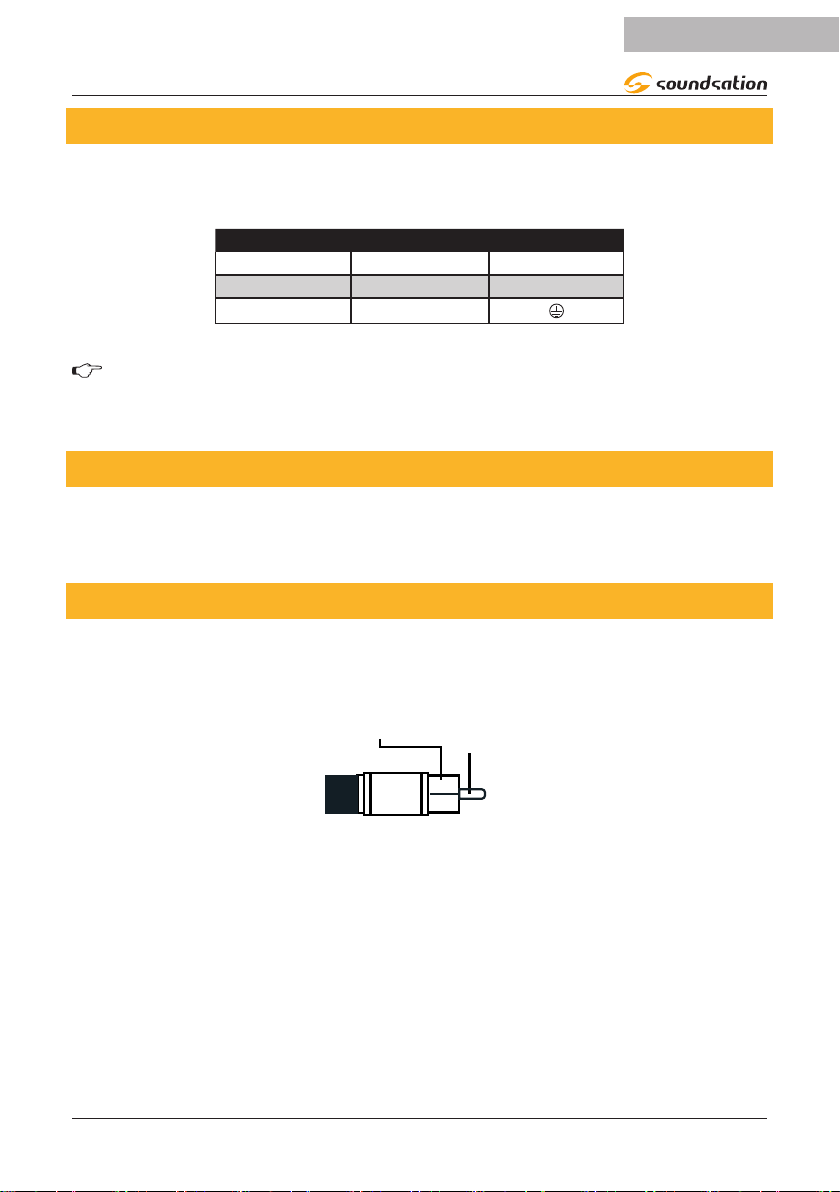
4.1. RCA Unbalanced Cables
Use RCA cables to connect unbalanced sources with RCA output connectors to RCA IN
input of the monitor (CD Player, MP3 Player, Etc.).
Center
Signal
Body
Ground / Shield

8
ENGLISH
CLARITY S-10 User manual
4.2. TS JACK 1/4” Balanced Cables
The Combo input in the rear panel accepts the balanced 1/4” (6.3mm) TS jack.
Balanced use of 1/4” jack TS connector
Strain relief
clamp
Sleeve
Tip
Sleeve
Ground shield
Ring Ring
Cold (- Ve)
Tip
Hot (+ Ve)
4.3. XLR Balanced Cables
The Combo Input and the XLR Output in the rear panel accepts also balanced XLR
connectors. The pin-out is as follows:
MIC 1 MIC 2 MIC 3 MIC 4
MIC
LINE
MIC
LINE
MIC
LINE
MIC
LINE
3
21
1.Ground/Shield
3.Cold (-)2.Hot(+)
12
3
9
ENGLISH
CLARITY S-10 User manual
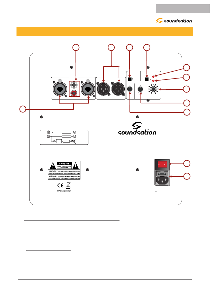
5. REAR PANEL
LOW CUT
LOW CUT
INPUT
L
R
HIGH
CUT
PHASE
L
R
OUTPUT
SUBWOOFER
ONOFF
POWER
CLARITY S-10
ACTIVE SUBWOOFER
INPUT OUTPUT
LOW CUT PHASE
R L LR
(Hz)
ON
OFF
NORM REV
CLIP
POWER
LEVELHIGH CUT(Hz)
100 100
120 12080 80 100
220-240V /60Hz
T5AL250V
1
2
RL
R
L
5
4
3
6
7
89
10
12
11
1)^IEC Socket with Fuse holder
Plug the power cord into an AC socket properly congured for your particular model. In
case of fuse burn, to prevent the risk of re and damaging the unit, please use only of
the recommended fuse type as indicated in the rear panel silkscreening. Before replac-
ing the fuse, make sure the unit turned o and disconnected from the AC outlet
2)^POWER Switch
Press power switch to ON position to turn the subwoofer on, and to OFF position to
turn it o. When the switch is in the ON position, it lights up and also the POWER LED
(6) is on.

10
ENGLISH
CLARITY S-10 User manual
3)^LOW CUT CONTROL
This knob adjusts the cuto frequency for low frequency attenuation between 80Hz
and 120Hz. This adjustment is only possible if the LOW CUT Switch (9) is ON.
4)^HIGH CUT CONTROL
This knob adjusts the cuto frequency for attenuation of the high frequencies output
from the subwoofer in the range 80Hz - 120Hz.
5)^LEVEL CONTROL
This knob is used to adjust the output audio signal level of the Subwoofer
6)^POWER INDICATOR
When the power cord is connected to the AC power connector and the power switch is
in the ON position, the POWER indicator (LED) lights.
7)^CLIP INDICATOR
This LED lights up when audio signal level is too high. Some ashes of this LED may be
normal, but if it stays on for a long time, you need to lower the level of the audio signal
output.
8)^PHASE SWITCH
Switches the phases of the subwoofer output. The switch should be set to [NORM]
in most situations, but in combination with some speaker layouts switching to [REV]
setting may improve Low-Frequency response. Select the setting that provide the best
bass response in your system.
9)^LOW CUT SWITCH
When this switch is ON, the low frequencies are attenuated prior to output via the
OUTPUT L and R connectors at the frequency set by the LOW CUT Control (3). The
Low-Frequency attenuation cuto frequency can be adjusted via the LOW CUT control.
10)^OUTPUT L/R Connectors
These are the subwoofer output connectors. The input signals received at the INPUT L
and R connectors, are output via the OUTPUT L and R connectors, respectively.
Low frequency reproduction characteristics can be adjusted via the LOW CUT switch
and LOW CUT Control.
11)^RCA INPUT Connectors
This connectors accept RCA unbalanced cables for audio signals receiving.
12)^COMBO INPUT CONNECTORS
This connectors accept XLR balanced cables and 1/4” (6.3mm) TS jack balanced cables,
for audio signals receiving.
11
ENGLISH
CLARITY S-10 User manual
6. SPECIFICATIONS
Speaker Type Active Subwoofer
Mains Power 220-240V~/50-60Hz
Fuse T5AL250V
Frequency response (-10dB) 30Hz - 150Hz
Woofer 10” Paper Cone
Woofer Output Power 350W RMS
Amplier Class AB
SPL (1m axial direction) 118dB
Audio Input Connections Balanced type 1/4”TS/ XLR interface,unbalanced RCA
Cabinet Material MDF
Dimensions (WxDxH) 300 x 320 x 300 mm
Weight 12,8Kg
Packing Dimensions (WxDxH) 355 x 395 x 380 mm
Packing Weight 15,5Kg
Our products are subject to change. Modications to technical features remain subject to change without notice

12
ENGLISH
CLARITY S-10 User manual
7. WARRANTY AND SERVICE
All SOUNDSATION products feature a limited two-year warranty. This two-year warranty is specic
to the date of purchase as shown on your purchase receipt.
The following cases/components are not covered from the above warranty:
• Any accessories supplied with the product
• Improper use
• Fault due to wear and tear
• Any modication of the product eected by the user or a third party
SOUNDSATION shall satisfy the warranty obligations by remedying any material or manufacturing
faults free of charge at SOUNDSATION’s discretion either by repair or by exchanging individual
parts or the entire appliance. Any defective parts removed from a product during the course of a
warranty claim shall become the property of SOUNDSATION.
While under warranty period, defective products may be returned to your local SOUNDSATION
dealer together with original proof of purchase. To avoid any damages in transit, please use the
original packaging if available. Alternatively you can send the product to SOUNDSATION SERVICE
CENTER – Via Enzo Ferrari , 10 – 62017 Porto Recanati - Italy . In order to send a product to service
center you need an RMA number. Shipping charges have to be covered by the owner of the
product.
For further information please visit www.soundsationmusic.com
8. WARNING
PLEASE READ CAREFULLY – EU and EEA (Norway, Iceland and Liechtenstein) only
This symbol indicates that this product is not to be disposed of with your household waste, ac-
cording to the WEEE Directive (2202/96/EC) and your national law.
This product should be handed over to a designated collection point, e.g., on an authorized one-
for-one basis when you buy a new similar product or to an authorized collection site for recycling
waste electrical and electronic equipment (WEEE).
Improper handling of this type of waste could have a possible negative impact on the environ-
ment and human health due to potentially hazardous substances that are generally associated
with EEE. At the same time, your cooperation in the correct disposal of this product will contribute
to the eective usage of natural resources.
For more information about where you can drop o your waste equipment for recycling, please
contact your local city oce, waste authority, approved WEEE scheme or your household waste
disposal service.

13
ITALIANO
SOMMARIO
1. DISIMBALLAGGIO ......................................................................................16
2. DESCRIZIONE .............................................................................................16
2.1. Caratteristiche Principali.............................................................................................................. 16
3. CONNESSIONE ALLA RETE ELETTRICA ....................................................17
4. CONNESSIONI AUDIO ..............................................................................17
4.1. Cavi RCA non Bilanciati................................................................................................................ 17
4.2. Cavi JACK TS 1/4” Bilanciati........................................................................................................ 18
4.3. Cavi XLR Bilanciati.......................................................................................................................... 18
5. PANNELLO POSTERIORE ...........................................................................19
6. SPECIFICHE .................................................................................................21
7. GARANZIA E ASSISTENZA ........................................................................22
8. AVVISO ........................................................................................................22
14
ITALIANO
IMPORTANTI SIMBOLI DI SICUREZZAIMPORTANTI SIMBOLI DI SICUREZZA
Il simbolo è usato per indicare che in questa apparecchiatura sono
presenti alcuni terminali sotto tensione pericolosi, anche in condizioni
di normale funzionamento, che possono costituire rischio di scosse
elettriche o di morte
Il simbolo viene utilizzato nella documentazione di servizio per indi-
care che uno specico componente può essere sostituito esclusiva-
mente dal componente specicato nella documentazione per motivi di
sicurezza.
Terminale di Terra
Corrente/Tensione alternata
Terminale in tensione pericoloso
Indica che l’apparato è acceso
Indica che l’apparato è spento
WARNING: Precauzioni da osservare per evitare il pericolo di ferimento o di morte
per l’utilizzatore.
CAUTION: Precauzioni da osservare per evitare danni all’apparecchio.
CURA DEL PRODOTTO
fLeggete queste istruzioni
fConservate queste istruzioni
fRispettate tutte le avvertenze
fSeguite tutte le istruzioni
1) ACQUA / UMIDITA
L’apparecchio deve essere protetto dall’umidità e dalla pioggia, non può essere usato
in prossimità di acqua; ad esempio nei pressi di una vasca da bagno, di un lavandino, di
una piscina, etc.
2) Calore
L’apparecchio deve essere posto lontano da fonti di calore come radiatori, stufe o altri
apparecchi che producono calore.

15
ITALIANO
MANUALE D’USO CLARITY S-10
3) VENTILAZIONE
Non ostruite le prese d’aria per la ventilazione: ciò potrebbe provocare incendi. Installa-
te sempre l’unità secondo le istruzioni del produttore.
4) Introduzione di oggetti e liquidi
Non introdurre oggetti o versare liquidi all’interno dell’apparato per ragioni di sicurezza
5) Cavo di alimentazione e spina
Evitate che il cavo di alimentazione venga calpestato o schiacciato, in particolare in
prossimità delle spine, delle prese e del punto in cui fuoriesce dall’apparecchio. Non
vanicate la nalità di sicurezza della spina con messa a terra. Una spina normale o
“polarizzata” ha due soli terminali; una spina con messa a terra ha un terzo polo di
terra. Questo ulteriore terminale serve per la vostra sicurezza. Se la spina fornita non si
inserisce nella presa, consultate un elettricista per l’eventuale sostituzione.
6) ALIMENTAZIONE
L’apparecchio deve essere collegato alla sorgente di alimentazione elettrica del tipo
indicato sull’apparecchio o descritto nel manuale. In caso contrario si potrebbero
provocare danni al prodotto ed eventualmente all’utente. Staccate la spina in caso di
temporali o quando non viene utilizzato per lunghi periodi di tempo.
7) FUSIBILE
Per evitare il rischio di incendi e di danni all’unità, utilizzate solo il tipo di fusibile
descritto nel manuale. Prima di sostituire il fusibile, assicuratevi che l’apparecchio sia
spento e scollegato dalla presa di corrente.
8) Collegamento alla rete elettrica
Il collegamento elettrico improprio può invalidare la garanzia del prodotto.
9) RUMORE ED INTERFERENCE
Non utilizzare il dispositivo in prossimità di TV, radio, apparecchiature stereo, telefoni
cellulari o altri dispositivi elettrici. In caso contrario, il dispositivo, la TV o la radio po-
trebbero generare rumore ed interference.
10) Pulizia
Pulite solo con un panno asciutto. Non utilizzate solventi come benzolo o alcol.
11) Manutenzione
Non eettuate qualsiasi altro intervento al di fuori di quelli descritti nel manuale. Per
eventuale assistenza rivolgetevi solo a personale qualicato. Utilizzate solo accessori /
componenti suggeriti dal produttore.

16
ITALIANO
MANUALE D’USO CLARITY S-10
1. DISIMBALLAGGIO
Grazie per aver acquistato lo studio Subwoofer CLARITY. Ogni unità è stata testata e
spedita in perfette condizioni operative. Disimballare con cura il cartone e controllare il
contenuto per assicurarsi che tutte le parti siano presenti e in buone condizioni
f1 x Studio Subwoofer CLARITY S-10
f1 x Cavo di Alimentazione
fQuesto Manuale di istruzioni
In caso di danni durante il trasporto, informare immediatamente lo spedizioniere e
conservare il materiale di imballaggio per l’ispezione. Si prega di conservare il cartone
originale e tutti i materiali di imballaggio. Se l’unità deve essere restituita al produttore,
è importante che l’unità venga restituita nella confezione originale del produttore. Si
prega di non intraprendere alcuna azione senza prima contattarci
2. DESCRIZIONE
Il subwoofer attivo da studio da 10” CLARITY S-10 è stato progettato al ne di ori-
re, ai musicisti,ai tecnici del suono ed ai produttori musicali, una risposta profonda e
dinamica alle basse frequenze e quindi bassi precisi e chiari nel suono per un’espe-
rienza musicale completa con 350 watt di amplicazione di classe AB. L’ampia scelta di
ingressi posizionati nel pannello posteriore (XLR, 1/4 “TS , RCA), garantisce la semplicità
di utilizzo.Il design moderno e ranato e la nitura nero satinato rendono questo sub-
woofer da studio elegante ed adatto a molti ambienti.
2.1. Caratteristiche Principali
fSubwoofer Attivo
f350W RMS di Potenza di uscita
fAmplicatore in classe AB
fRisposta in Frequenza tra 30Hz e 150Hz a -10dB
fWoofer da 10“
fRegolazione dell’attenuazione delle Alte Frequenze (from 80Hz to 120Hz)
fRegolazione dell’attenuazione delle Basse Frequenze (from 80Hz to 120Hz)
fIngressi bilanciati di tipo 1/4 “TS / XLR e non bilanciati di tipo RCA.
fFinitura satinata in bianco o nero a seconda del modello acquistato
fInvolucro robusto in MDF
17
ITALIANO
MANUALE D’USO CLARITY S-10
3. CONNESSIONE ALLA RETE ELETTRICA
Collegare il dispositivo alla rete elettrica con il cavo di alimentazione in dotazione. La
corrispondenza del cavo è la seguente:
Cavo Pin Internationale
Marrone Fase L
Blù Neutro N
Giallo/Verde Terra
ATTENZIONE: Il cavo di terra deve essere sempre connesso! Prestare atten-
zione alla sicurezza! Prima di mettere in funzione per la prima volta, l’instal-
lazione deve essere approvata da un esperto.
4. CONNESSIONI AUDIO
Sul pannello posteriore del subwoofer ci sono vari tipi di connessioni audio che garan-
tiscono facilità d’uso. Vedere le seguenti immagini che mostrano il cablaggio interno di
questi cavi. Assicurarsi di utilizzare solo cavi di alta qualità.
4.1. Cavi RCA non Bilanciati
Utilizzare cavi RCA per collegare sorgenti non bilanciate con connettori di uscita RCA
all’ingresso stereoi RCA IN del Subwoofer (lettori CD, lettori MP3, ecc.),
Centro
Segnale
Corpo
Terra / Massa

18
ITALIANO
MANUALE D’USO CLARITY S-10
4.2. Cavi JACK TS 1/4” Bilanciati
Gli ingressi L/R Combo nel pannello posteriore accettano jack TS 1/4 ”(6,3 mm) bilan-
ciati.
Uso bilanciato del connettore Jack 1/4” TS
Strain relief
clamp
Sleeve
Tip
Sleeve
Ground shield
Ring Ring
Cold (- Ve)
Tip
Hot (+ Ve)
4.3. Cavi XLR Bilanciati
Gli ingressi L/R Combo nel pannello posteriore accettano anche connettori XLR bilan-
ciati. Il pin-out è il seguente:
MIC 1 MIC 2 MIC 3 MIC 4
MIC
LINE
MIC
LINE
MIC
LINE
MIC
LINE
3
21
1.Ground/Shield
3.Cold (-)2.Hot(+)
12
3

19
ITALIANO
MANUALE D’USO CLARITY S-10
5. PANNELLO POSTERIORE
LOW CUT
LOW CUT
INPUT
L
R
HIGH
CUT
PHASE
L
R
OUTPUT
SUBWOOFER
ONOFF
POWER
CLARITY S-10
ACTIVE SUBWOOFER
INPUT OUTPUT
LOW CUT PHASE
R L LR
(Hz)
ON
OFF
NORM REV
CLIP
POWER
LEVELHIGH CUT(Hz)
100 100
120 12080 80 100
220-240V /60Hz
T5AL250V
1
2
RL
R
L
5
4
3
6
7
89
10
12
11
1) PRESA IEC con PORTAfUSIBILE
Collegare il cavo di alimentazione a una presa AC correttamente congurata per il
modello specico. In caso di bruciatura del fusibile, per prevenire il rischio di incendio
e danneggiamento dell’unità, si prega di utilizzare solo il tipo di fusibile raccomanda-
to come indicato nella serigraa del pannello posteriore. Prima di sostituire il fusibile,
assicurarsi che l’unità sia spenta e scollegata dalla presa AC
2) Interruttore di alimentazione
Premere l’interruttore di alimentazione in posizione ON per accendere il subwoofer e in
posizione OFF per spegnerlo. Quando l’interruttore è in posizione ON, questo si illumi-
na ed anche il LED POWER (6) è acceso.

20
ITALIANO
MANUALE D’USO CLARITY S-10
3) CONTROLLO LOW CUT
Questa manopola regola la frequenza di taglio per l’attenuazione delle basse frequenze
tra 80Hz e 120Hz. Questa regolazione è possibile solo se l’interruttore LOW CUT (9) è in
posizione ON.
4) CONTROLLO HIGH CUT
Questa manopola regola la frequenza di taglio per l’attenuazione delle alte frequenze
emesse dal subwoofer nell’intervallo 80Hz - 120Hz.
5) MANOPOLA VOLUME
Questa manopola viene utilizzata per regolare il livello del segnale audio in uscita del
subwoofer.
6) Indicatore Alimentazione
Quando il cavo di alimentazione è collegato al connettore di alimentazione AC e l’inter-
ruttore di alimentazione è in posizione ON, l’indicatore POWER (LED) si illumina.
7) INDICATORE CLIP
Questo LED si illumina quando il livello del segnale audio è troppo alto. Alcuni lam-
peggi di questo LED possono essere normali, ma se rimane acceso per lungo tempo, è
necessario abbassare il livello dell’uscita del segnale audio.
8) Interruttore di Fase
Cambia le fasi dell’uscita del subwoofer. L’interruttore dovrebbe essere impostato su
[NORM] nella maggior parte dei casi, ma in combinazione con alcune combinazioni/
disposizioni dei diusori, il passaggio all’impostazione [REV] può migliorare la risposta
delle basse frequenze. Selezionare l’impostazione che fornisce la migliore risposta dei
bassi nel pproprio sistema
9) INTERRUTTORE LOW CUT
Quando questo interruttore è su ON, le basse frequenze vengono attenuate prima
dell’uscita tramite i connettori OUTPUT L e R alla frequenza impostata dal controllo
LOW CUT (3). La frequenza di taglio dell’attenuazione per la bassa frequenza può esse-
re regolata tramite il controllo LOW CUT
10) CONNETORI DI USCITA L/R
Questi sono i connettori di uscita del subwoofer. I segnali di ingresso ricevuti sui con-
nettori INPUT L e R, vengono emessi rispettivamente tramite i connettori OUTPUT L e R.
Le caratteristiche di riproduzione per la bassa frequenza possono essere regolate trami-
te l’interruttore LOW CUT e il controllo LOW CUT.
11) CONNETTORI DI INGRESSO DI TIPO RCA
Questi connettori accettano cavi non bilanciati di tipo RCA per la ricezione di segnali
audio.
12) CONNETTORI DI INGRESSO DI TIPO COMBO
Questi connettori accettano cavi bilanciati XLR e cavi bilanciati jack 1/4 ”(6,3 mm) TS,
per la ricezione di segnali audio.
This manual suits for next models
1
Table of contents
Languages:
Other Sound Sation Subwoofer manuals


