Soundavo PMX-6600 User manual
OWNERS MANUAL
POWER MANAGEMENT
PROFESSIONAL AUDIO
PMX-6600

WARNING
1. Do not place or install this device in an area where it can be exposed to excessive amounts of
dust, humidity, oil, smoke, or combustible vapors.
2. To prevent risk of electrical shock or fire hazard, due to overheating do not obstruct unit’s
ventilation openings.
3. Do not install near any source of heat, including other units that may produce heat.
4. Do not expose this device to excessively high temperatures. Do not place it in, on, or near heat
sources, such as a fireplace, stove, radiator, etc. Do not leave it in direct sunlight
5. Do not touch the device, the power cord, or any other connected cables with wet hands.
6. This device ventilates excessive heat through the slots and openings in the case. Do not block
or cover these openings. Ensure that the device is in an open area where it can get sufficient
airflow to keep from overheating.
7. Only clean unit with a dry cloth.
8. Unplug unit during lightning storms or when not used for an extended period of time.
9. Protect the power cord from being walked on or pinched, particularly at the plugs.
10. Use unit only with accessories specified by the manufacturer.
11. Refer all servicing to qualified personnel.
2
Thank you for purchased Soundavo product. Please read this
entire manual before using this device, paying extra attention to
these safety warnings and guidelines. Please keep this manual in
a safe place for future reference.

3
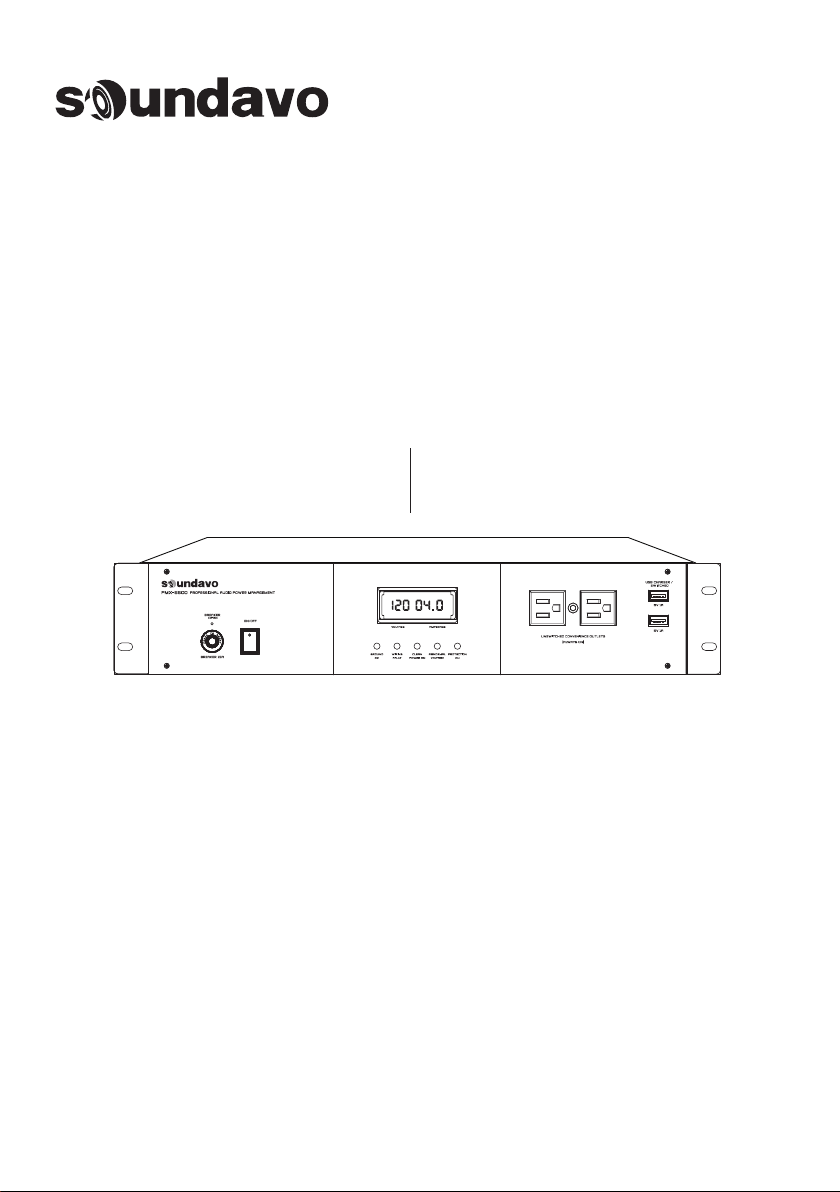
The PMX-6000 Professional Audio Power Management is a power conditioner
and sequencer with excellent feature including the status and alert capabilities: a
voltage meter and amperage meter for real-time analysis, LED status for ground-
ing/polarity/noise filtering/abnormal voltage/surge protection, and an audio
alarm for unsafe voltage. The multi-stage noise filtering for reduces frequency
interference RFI & Electromagnetic Interference EMI. Specifically designed and
engineered to provide a stable power and good circuit protection to your system.
Power-Up in 3 delayed outlet groups from zone 1 to zone 3 as Digital, Analog and
High Power Filtered outlets for 6 seconds delay time between each zone, those 3
zones are powered off in reverse sequence. It will prevent annoying and some-
times damaging THUMPS and POPS by turning power amplifiers ON last and OFF
first. Sequentially powering ON multiple electrical / electronic components will
also help manage high inrush currents that can cause circuit breakers to trip and
current-limited power supplies to shut down. Which is a excellent feature for
Home Audio, Instrument Rigs, Sound Recording Studio or Pro Audio/DJ equip-
ment with power amplifier, active speaker and preamp/mixer application.
• Outlets are Individually optimized for digital, analog, and high-power devices
(4 x each)
• Time delayed outlets with 6 seconds of each group for high current devices
help protect speakers and amplifiers
• RFI Filtering Technology to provide greater than 99% of noise filtering
• 12 switched back-panel outlets and 2 unswitched front-panel outlets
• Two switched USB chargers on front panel
• Circuit breaker
• 12-volt trigger input/output with bypass switch provided to allow triggering
from a control system or other component
• Front panel digital LED meter display incoming AC line voltage & amperage
• Dimensions: Width 438mm (19”) x Height 88mm (2U) x Depth 250mm
• Weight: 6.8+ kg
Spec:
Feature:
•14-outlets power conditioner
•3-stages power up/power down system
•Voltage: 120VAC /15A MAX
•Accessory Outlets: 12 Switched /2Un-Switched /2Switched USB charger
4
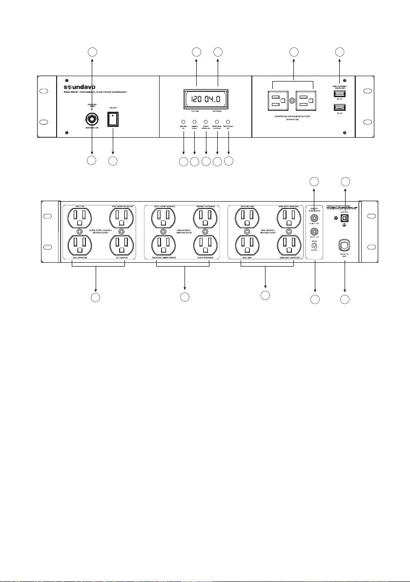
Front/Rear panel
7
6
5
4
3
89
13
11
1014
12 16 17 18 19
15
2
1
2. GROUND OK: When this is on, the PMX-6600 is
plugged into a properly grounded power source. If
the LED is not on, unplug the unit from the power
source and correct the fault
4. Clean Power On: This LED indicates that the
PMX-6600 is providing clean, beautiful AC power to
all connected components.
5. Abnormal Voltage: When this LED is ON, the
PMX-6600 is warning about under/over voltage
(greater than 132VAC or less than SOVAC).
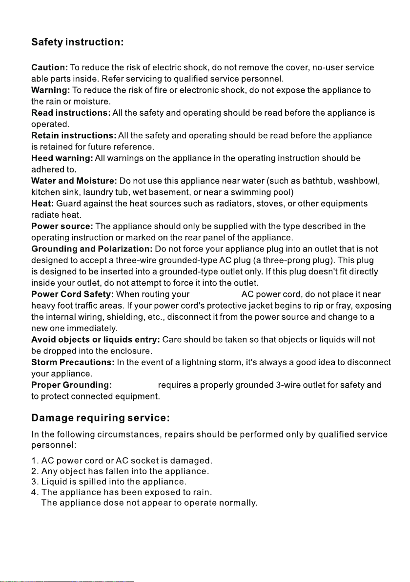
7. Digital Audio (Switched) Outlets: These
1. ON/OFF Switch: Once the PMX-6600 is plugged into
agrounded 120VAC outlet, turning the front panel
POWER switch to the ON position will sequentially
power the components plugged into the rear panel
outlets.
3. Wiring Fault: This indicates the LINE and NEUTRAL
wires in the sourcearereversed. Unplug the unit
immediately and consult an electrician to fix the fault.
6. Protection ON: When this LED is on, the
PMX-6600’s power surge circuitry is function-
ing correctly. If this LED is OFF, the circuit has
malfunctioned. If it is OFF, unplug the unit
immediately.
outlets have aspecial filter circuit that is
designed to reduce AC supply interference to
your digital components (midi controller,
sampler, CD player). They also isolate the rest
of your system from noise generated by the
digital components themselves
8. Analog Audio Flier (Switched) Outlets: These
outlets have aspecial filter circuit that reduces
audible noise in your analog components
(audio interface, preamp, audio processor,
mixer console, projector)

5
9. High Current Filter(Switched) Outlets: These
outlets have a special filter circuit designed to
handle high current components like power
amplifiers or Active Speakers
10. Gold-Plated Ground Post: Provides a
connection point for any ungrounded
components.
11. Thermal Circuit Breaker: Protects the
PMX-6600 from power overload.
12. Breaker Open: When this LED is on the
thermal circuit breaker has tripped due to an
overload. Before resetting the breaker, find
the reason for the overload.
13. Ultra-High Current AC Power Cable: Integral
high power, heavy duty AC cable to maximize
power transfer to high current components
such as amplifiers.
REMOTE Mode: These require a 12 volt triggering
device such as that typically found in most power
receivers and audio pre-amp processors
WARNING: If the “BYPASS" switch is not engaged,
All “Switched" outlets will not supply power until a
12V trigger is present!
16. Voltage Meter: Three-character LED displays the
line voltage at the source.
18. Unswitched Convenience Outlets: These are
"always on” filtered power outlets
19. USB Charger: Two 5V/1A convenience chargers
for portable electronic devices.
Note: For best performance were commend plugging
analog components into the analog outlets and
digital to digital. It will not harmony components if
they are plugged into any other outlet
14. Bypass/Remote Switch: The PMX-6600 has
two power-on/off modes, one is through the
Power On/Off Switch on the front panel, and
the other one is through the external 12V
trigger. (Once the PMX-6600 is powered on
by “REMOTE” mode, then the Power On /Off
Switch on the front panel will not functional)
BYPASS Mode: For those who do not wish to
utilize the 12V triggering, aconvenient bypass
switch is located adjacent to the input and
output jacks. By switch to the “BYPASS"
position, the 2xUSB Chargers and 12 xRear
Panel Mounted Outlets (3 Zones) will be
operated when the front panel power on/off
switch is engaged.
15. Remote Turn On/Off: 3.5mm (1/8”) mono
mini-plug. Connect to aremote trigger device that
used aDC output to trigger is startup/shutdown
sequence. DC IN 2~30V
(Trigger In): Allows source components to
control and turn on the switched outlets into
operation of PMX-6600 DC OUT 12V (Trigger Out):
Provides 12V signal to control source
equipment or another PMX-6600 device for
sequencing of equipment.
17. Amperage Meter: Three-character LED displays
the amperage usedbyequipmentpluggedinto-
the PMX-6600.

Trouble Shooting
Symptom Possible Cause Remedy
The PMX-6600 is not
receiving power.
Too many devices are connected,
causing an overload, tripping the
Thermal Circuit Breaker.
The component is plugged into a
switched outlet and the PMX-6600
has not been turned On.
The PMX-6600 is plugged into a
switched outlet, but power on the
component is not On. In some
instances, a component plugged
into a switched outlet won’t receive
power when the PMX-6600 is
turned On unless the component
power is also switched On.
• Turn the PMX-6600 power switch
to ON position.
• Make sure the PMX-6600’s AC
power plug is plugged into a
properly grounded 120 volts
(nominal) wall outlet.
• In some households, a wall switch
may need to be turned on to make
the wall outlet active. Try turning on
the light switches located near the
wall outlet.
• Press the PMX-6600 resettable
circuit breaker button in to reset.
Please allow 10 minutes before
attempting to reset. If reset too
soon, the breaker will prematurely
sense power overload and not allow
the PMX-6600 to operate.
• If the circuit breaker continues to
trip, try moving one or more
components to another PMX-6600.
Too much current may be drawing
through one PMX-6600.
• Turn the PMX-6600 On.
• Or, please double check see if the
tigger switch has been selected to
“BYPASS” positions. If the BYPASS
switch is not engaged, All
“Switched" outlets will not supply
power until a 12V trigger is present!
• Turn the component power On.
The PMX-6600 is sharing AC
power with equipment that is
not properly grounded.
• Connect your PMX-6600 to a
dedicated outlet.
• Try unplugging different compo-
nents from the PMX-6600 one at a
time to see if the noise stops.
• If a component is discovered to be
improperly grounded, attach a
copper wire from the component’s
chassis to the PMX-6600 grounding
post.
Component is not
receiving power.
Speakers emit a
humming or
buzzing noise.
The PMX-6600 is not turned On.
6
7
PMX-6600
PMX-6600
Table of contents


