SoundGraph Hummin' 3.03 User manual

-1-
Quick Guide
Version: 1.11.0224
SoundGraph, Inc.

-2-
List of Contents
Thank you for purchasing Hummin’3.03 Enclosure. Please check the contents in this package
listed below.
Hummin’3.03 Enclosure
iMON Pad Remote Control
24/5 power cable
Quick Guide
Hummin’3.03 Enclosure
iMON Pad Remote Control
24/5 power cable
Quick Guide
In case of a barebone kit including Hummin’3.03 Enclosure, FingerVU 1016S/1016W
(Wired/Wireless) Monitor, FingerVU WUD (Wireless USB) Dongle and FingerVU 1016D
(Docking Station) may be included, or a set of mainboard, power supply and HDD
removable bay may be assembled in the enclosure.
Nomenclature
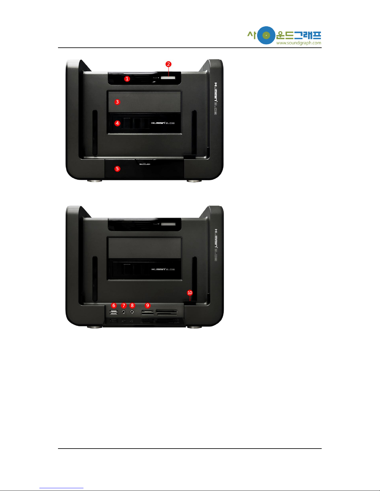
Components of Hummin’3.03 Enclosure are listed with simple descriptions.
-3-
①Infrared (IR) receiver
②Power button
③5.25”Disk Driver bay (upper)
④Removable Hard Disk Drive bay (lower)
⑤Front I/O panel
⑥Front USB port
⑦Mic. input
⑧Headphone output
⑨Card reader
⑩Front FingerVU 1016S/1016W docking connector
-4-
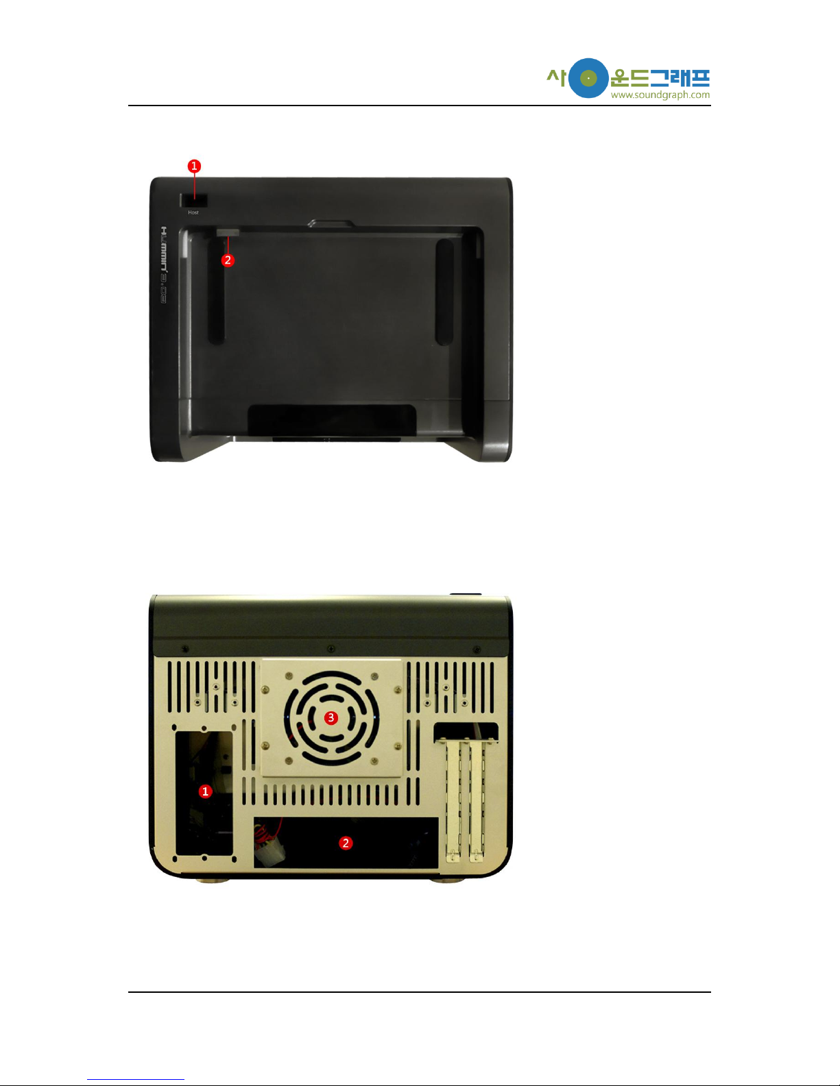
①FingerVU WUD connector
②Top FingerVU 1016S/1016W docking connector
①Mounting position for microATX power supply
②Mounting position for bracket on mainboard
③Fan cover

-5-
Software Installation
Hummin’3.03 Enclosure can be used with iMON Manager Touch Frame, and HD Frame. These
applications are provided with FingerVU 1016S/1016W (Wired/Wireless) Monitor. Please refer to
the installation CD in FingerVU 1016S/1016W package you purchased.
Hardware Installation
This section provides detailed installation procedure of Hummin’3.03 Enclosure. Please follow the
description of each step carefully.
1. Remove top cover
Remove the top cover of the enclosure by releasing 3 screws and pulling the cover
backward.
2. Remove fan cover on backside
Remove the fan cover on backside of the enclosure by releasing 4 screws. This is
necessary step for connection of Optical Disk Drive cables in further steps.
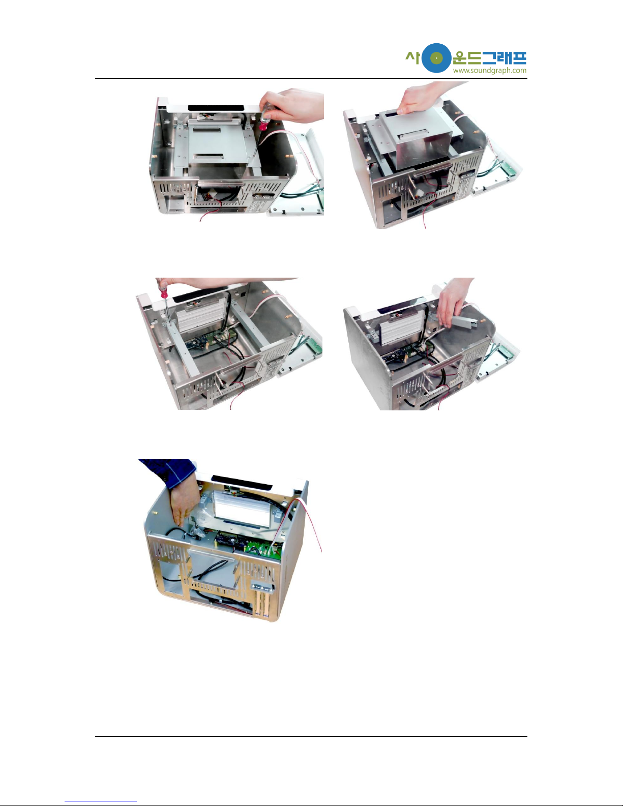
3. Remove 5.25”disk drive bay
-6-
Remove the 5.25”disk drive bay from the drive bay support by releasing 4 screws.
4. Remove drive bay support
Remove the drive bay support from the enclosure by releasing 4 screws (B type).
5. Remove screw set for assembly
Remove the screw set for assembly placed on backside of the front panel.
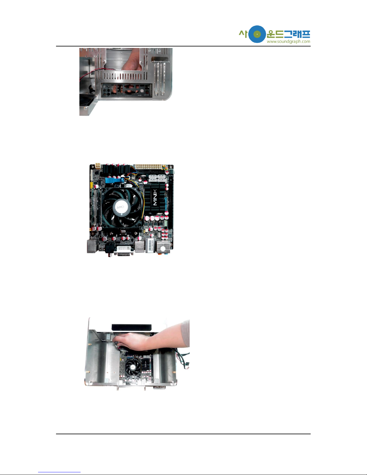
6. Mount Bracket on Mainboard
-7-
Mount the bracket (included in the mainboard product) on back side of Hummin’3.03
Enclosure.
7. Install Mainboard Components
Hummin’3.03 Enclosure supports standard mini-ITX mainboards. Install CPU, CUP cooler
and memory as in the user guide of the mainboard. A video expansion card may be
installed after mounting the mainboard into the enclosure.
8. Mount mainboard
Mount the prepared mainboard into the enclosure with adjusting its position to the
mounted bracket.

-8-
9. Connect front USB cable
Connect the USB cable (USB 5 Pin) from the front I/O panel to the USB connection
header on the mainboard.
Please make sure that the orientation of the cable matches that of the USB
header. (Refer to Connection Guide for Hummin’3.03 Internal Cables.)
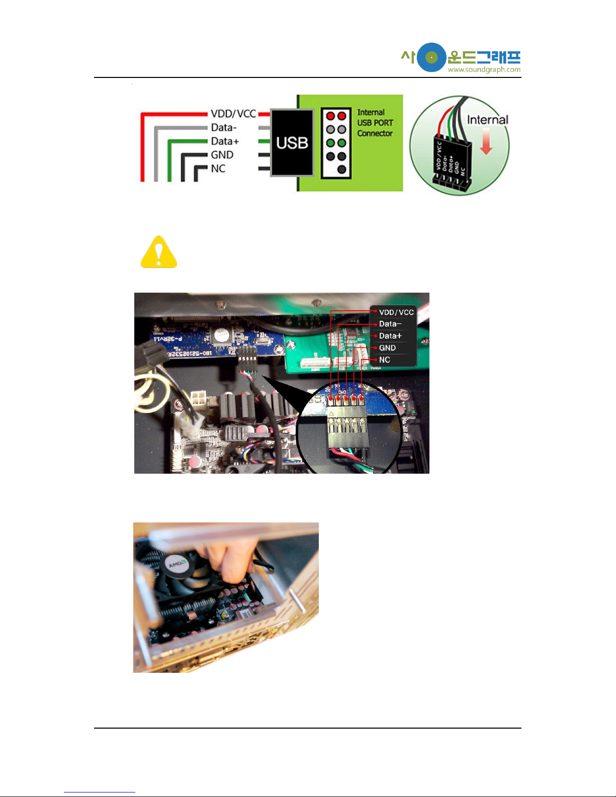
10. Connect USB cable from card reader
Connect the USB cable (USB 5 Pin) from the card reader to the USB connection header
on the mainboard.
Please make sure that the orientation of the cable matches that of the USB
header. Wrong connection can cause serious damage to the card reader and
the mainboard. In general, USB pin array follows its standard as shown
below. However, it may be different depending on mainboard manufacturer.
Please check user guide for the mainboard before connection of the USB
cable.
-9-
In this product, the other side of the USB 5 Pin cable is connected to the
card reader with the orientation shown below. Please check the connection
in this step.
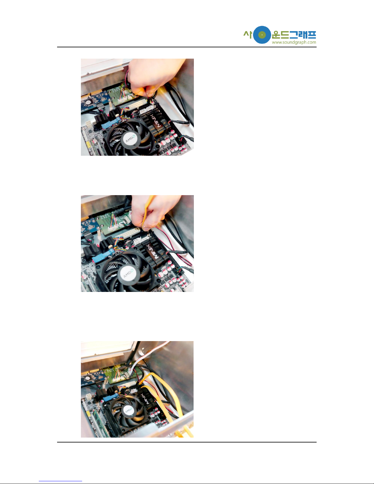
11. Connect front HD audio cable
Connect the front HD audio cable (HD Audio) from the front I/O panel to the speaker
head on the mainboard. (Refer to Connection Guide for Hummin’3.03 Internal Cables.)
-10-
12. Connect front power switch
Connect the front power cable (Power S/W) from the front I/O panel to the power head
on the mainboard. (Refer to Connection Guide for Hummin’3.03 Internal Cables.)
13. Connect SATA cable for removable 3.5”hard disk drive bay to mainboard
Connect one end of the SATA cable to one of the SATA connectors on the mainboard
and pull out the other side of the cable through the hole for the fan cover removed
before.
14. Connect SATA cable for hard disk drive to mainboard

-11-
Connect one end of SATA cable to one of the SATA connectors on the mainboard and
pull out the other side of the cable through the hole for the fan cover removed before.
15. Connect SATA cable for 5.25”optical disk drive to mainboard.
Connect one end of SATA cable to one of the SATA connectors on the mainboard and
pull out the other side of the cable through the hole for the fan cover removed before.
16. Connect 24/5 pin power supply cable to mainboard.
Connect the 24 pin socket from the 24/5 pin power supply cable to the ATX power
connector of the mainboard. (Refer to Connection Guide for Hummin’3.03 Internal
Cables.)
17. Connect 24/5 pin power supply cable to front I/O panel

-12-
Connect the 5 pin socket from the 24/5 pin power supply cable to the available power
connector (one not being used from the two “POWER”s) on the front I/O panel. (Refer to
Connection Guide for Hummin’3.03 Internal Cables.)
18. Mount power supply module
Hummin’3.03 Enclosure supports standard microATX power supply. Place and mount the
standard microATX power supply carefully to let the intake and exhaust fans circulate
cooling air inside the enclosure.
19. Connect 24/5 pin power supply cable to power supply module
Connect the 24 pin extension connector from the 24/5 pin cable (connected on the

-13-
mainboard before) to the 24 pin cable of the power supply module. Arrange the cables
not to block proper operation of other components.
20. Connect 4 pin auxiliary power cable to mainboard
Connect the 4 pin auxiliary power cable from the power supply module to the 4 pin
auxiliary power connector on the mainboard.
21. Connect 9 pin USB cable from top cover
Connect the USB 9 pin cable (USB 9 Pin) from the top cover to the 9 pin USB connection
header on the mainboard
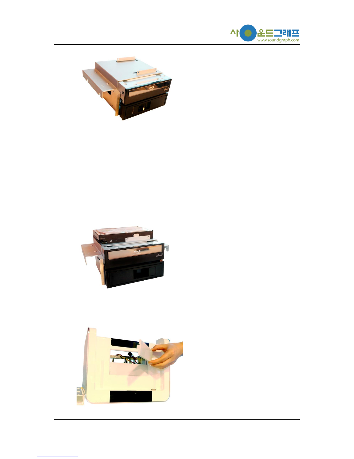
22. Mount optical disk drive (upper) and removable hard disk drive bay (lower)
-14-
In Hummin’3.03 Enclosure, a DVD drive or a Blu-ray drive having length within 180 mm
can be mounted in the 5.25”disk drive bay. The removable hard disk bay (lower bay in
the image above) is included in the Hummin’3.03 Enclosure barebone kit by default.
In case of mounting both the optical disk drive and removable hard disk drive bay, place
the removable hard disk drive bay at the lower position to facilitate air ventilation inside
the enclosure.
23. Mount master hard disk drive
Mount the master hard disk for OS installation onto the disk drive bay.
24. remove front ODD cover

-15-
Remove the cover for ODD bay to be used. In the case when both the ODD and
removable hard disk drive bay are mounted (at upper and lower position, respectively),
remove all the two ODD bay covers.
25. Mount drive bay support
Mount the drive bay support for the 5.25”disk drive bay.
26. Mount 5.25”disk drive bay
Mount the 5.25”disk drive bay on the drive bay support with screws.
27. Connect SATA and power cables to removable hard disk drive bay
Connect the SATA cable and power cables to the removable hard disk drive bay.

-16-
To change hard disk drive while OS is running, AHCI option needs to be
selected from AHCI Devices menu in mainboard BIOS setup. AHCI mode is
compatible with Windows Vista and Windows 7.
28. Connect SATA and power cables to 5.25”optical disk drive
Connect SATA and power cables to the 5.25”optical disk drive.
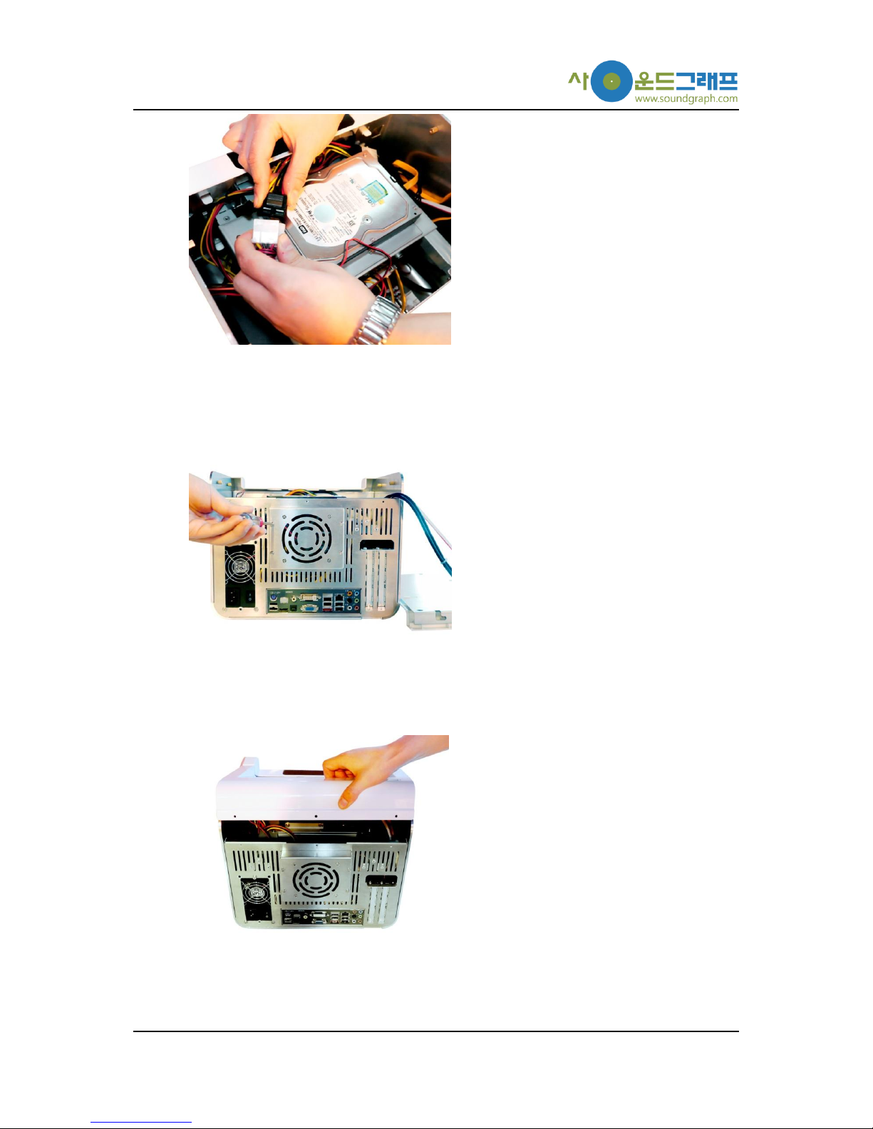
29. Connect SATA and power cables to 3.5”hard disk drive
Connect SATA and power cables to the 3.5”hard disk drive. 3.5”
30. Connect fan cable
-17-
Connect the fan cable from the removed fan cover on backside of the enclosure to the
power supply module.
31. Assemble fan cover
Assemble the removed fan cover on backside of the enclosure. Prior to this step, arrange
the cables not to block the fan operation.
32. Assemble top cover
Finalize the installation by assembling the top cover with screws.

-18-
Latest Quick Guide
Homepage > User Forums & Support > Customer Support > Hummin’ HTPC Products
The latest version of this Quick Guide can be downloaded from the customer support page linked
above.
Customer Support Information
Customer Support Center: +82-70-7018-5373
Online User Forums (Sign-up required): http://www.soundgraph.com/support-mesg-en
Homepage: http://www.soundgraph.com/
Connection Guide for Hummin’ 3.03 Internal Cables
Please refer to the connection guide shown in the next page for all the cables inside Hummin’
3.03 to be connected correctly.

-19-
Table of contents
Popular Enclosure manuals by other brands

ABB
ABB ACS550 Series quick start guide

RaidSonic
RaidSonic IB-288StU3Eb-Wh Specifications

Antec
Antec Veris Fusion 430 Manual Del Usuario

StorCase Technology
StorCase Technology Data Express DE200i-S quick start guide

American Products
American Products INDEPENDENCE owner's manual

Macpower & Tytech
Macpower & Tytech Pleiades USB/LAN User manual & installation guide

Addonics Technologies
Addonics Technologies AE5IDECSUF user guide
 user manual")
VIPowER
VIPowER Portable External Enclosure VP-9258(T) user manual

MidNite Solar
MidNite Solar MNBE-8D2x2 instructions

Rosewill
Rosewill ATX Computer Case R7329 user manual

Western Digital
Western Digital WDBABV0010ABK - Elements SE Portable Specifications

Martin Audio
Martin Audio W8LM Specifications


